Your Responsible Supplier Partner for Oil and Gas Products.

Grain Silo
Recent Products




Rencent Articles





Grain Silo
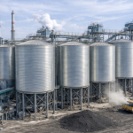
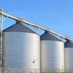
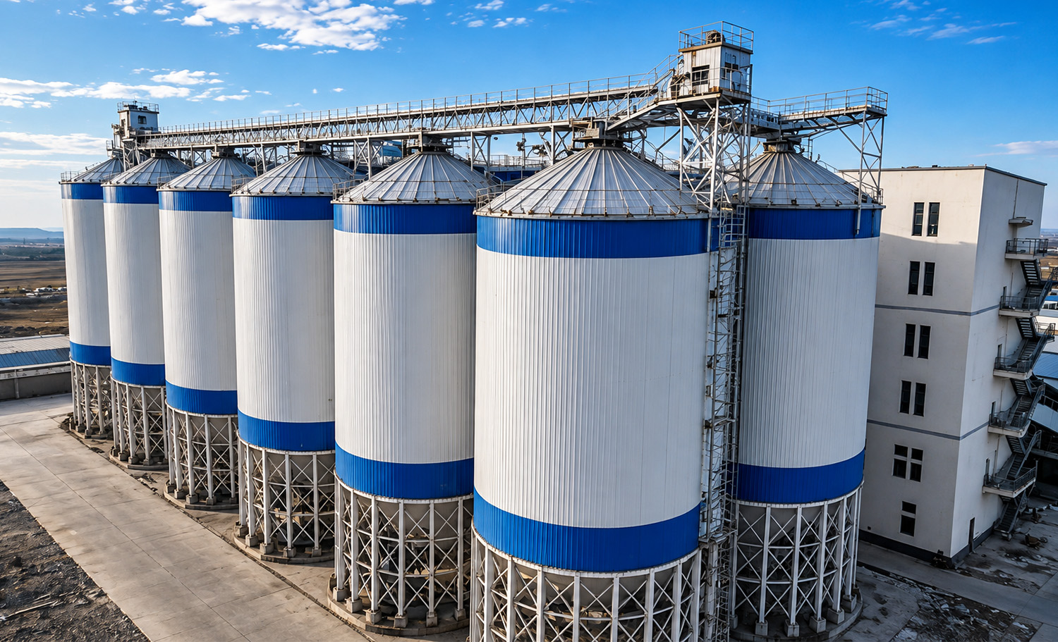
Capacity Range: Nominal series from 100 T to 15,000 T for different grain storage requirements.
Silo Configuration: Hopper-bottom and flat-bottom structures for different storage, turnover and unloading requirements.
Steel Structure: Corrugated hot-dip galvanized steel shell with vertical stiffeners, bolted joints and a conical roof.
Grain Storage: Designed for bulk storage of wheat, corn, rice, soybeans and other project-confirmed dry grains.
Storage Control: Aeration, temperature monitoring and level measurement support grain-condition management during storage.
System Scope: Grain receiving, pre-cleaning, optional drying, elevating and conveying, silo storage, aeration, temperature monitoring, discharge and electrical control can be coordinated as one grain storage system.
Grain silo systems built from hot-dip galvanized corrugated steel wall panels, vertical stiffeners, a bolted conical roof, sealed connections and either a hopper-bottom or flat-bottom structure provide enclosed storage for wheat, corn, rice, soybeans and other project-confirmed dry grains. Hopper-bottom configurations support frequent turnover and gravity unloading, while flat-bottom steel grain silos accommodate larger inventories and longer storage periods in farms, grain-processing plants, centralized reserve depots and bulk-handling terminals.
During operation, grain passes through receiving, pre-cleaning, optional drying, elevating and conveying, and controlled roof filling before entering the storage silo. During storage, aeration, temperature monitoring, level measurement and, where required, fumigation interfaces support grain-condition management. A gravity outlet or mechanical reclaim system then transfers the stored grain to downstream conveying or processing equipment.
OCTAL STEEL coordinates the silo body, grain receiving and handling equipment, optional drying system, aeration and monitoring system, discharge equipment, electrical control and civil interfaces according to the confirmed project scope. The final configuration is determined by grain type, bulk density, storage capacity, incoming moisture, storage duration, receiving and discharge capacity in TPH, site conditions and the required supply boundary.
Complete Grain Silo System Scope of Supply
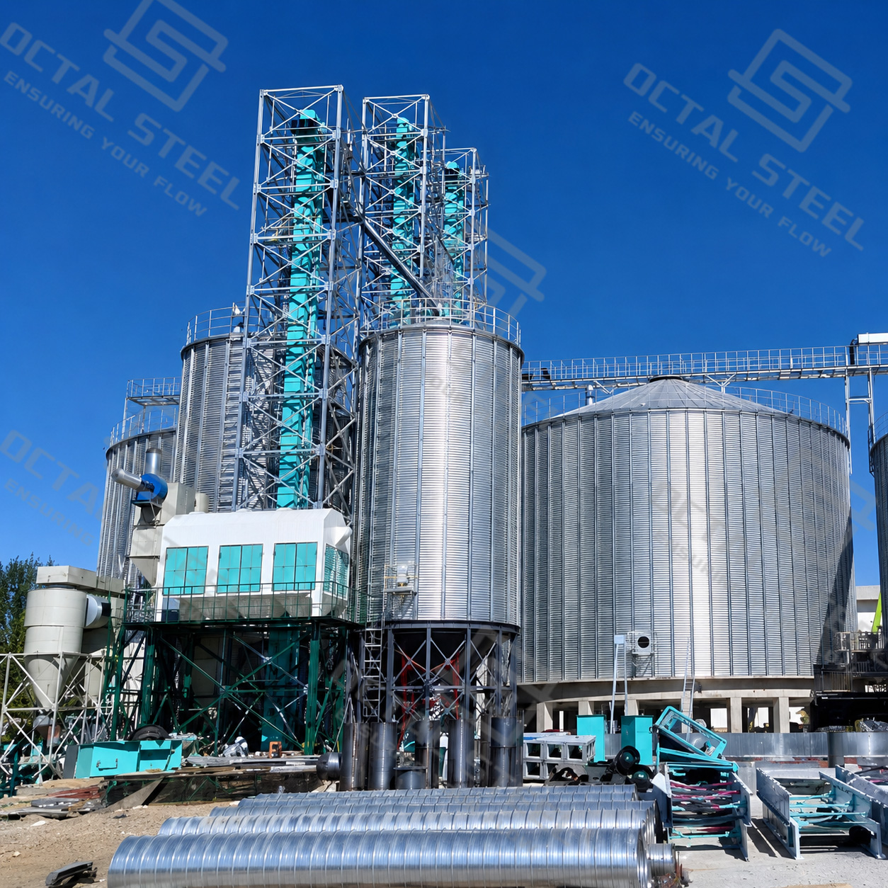
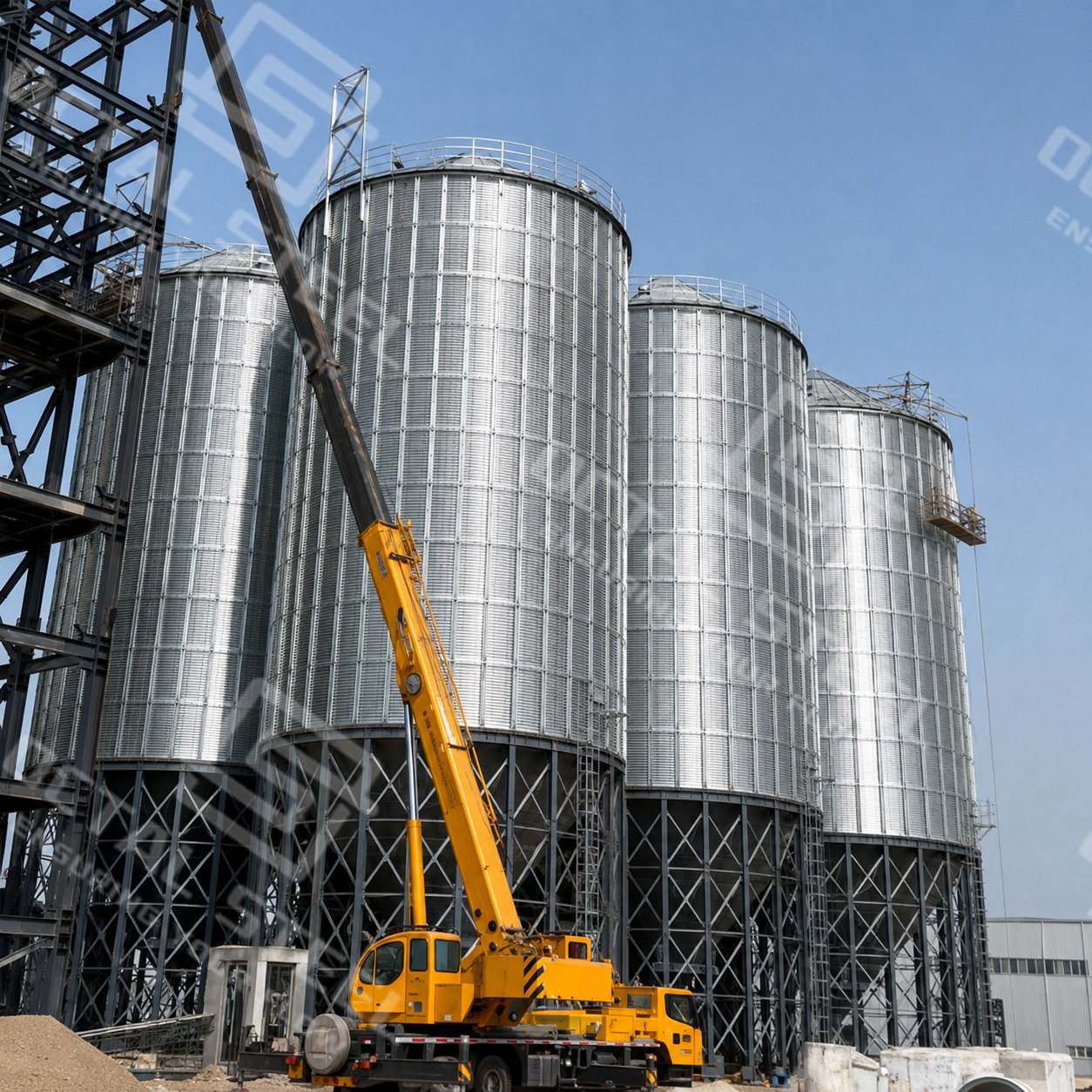
A grain silo project normally consists of more than the steel storage body itself. According to the customer’s process requirements, a complete grain storage system can include grain receiving, cleaning, drying, conveying, storage, grain conditioning, electrical control and supporting infrastructure.
The final scope of supply is configured according to grain type, total storage capacity, required handling capacity, incoming moisture, storage period, site conditions and the customer’s project responsibility boundary.
| System | Typical Equipment / Scope | Main Function |
|---|---|---|
| Silo Body System | Corrugated wall sheets, stiffeners, roof, bolts, sealant, access system and discharge components | Provide the main enclosed grain-storage structure |
| Grain Receiving System | Receiving pit, grating, receiving conveyor and dust collection | Receive grain from truck, rail or other incoming routes |
| Cleaning System | Pre-cleaner, magnet and impurity-separation equipment | Remove impurities before storage or drying |
| Grain Drying System | Dryer, heat source, fans and associated equipment where required | Reduce grain moisture to the required storage condition |
| Grain Handling System | Bucket elevator, chain conveyor, belt conveyor, screw conveyor and distributor | Transfer grain between receiving, storage and discharge points |
| Grain Conditioning System | Aeration, temperature monitoring, level monitoring and optional fumigation | Support grain-condition management during storage |
| Electrical & Automation | PLC/HMI, MCC, VFD, sensors, alarms and equipment interlocks | Coordinate and monitor system operation |
| Supporting Infrastructure | Elevator tower, catwalk, platforms and civil interfaces | Support equipment and connect the system with site infrastructure |
Note: Not every grain silo project requires all of the above systems. The final equipment configuration should be confirmed according to the actual grain process and agreed scope of supply.
Grain Silo Types, Specifications and Capacity Basis
Grain silos are mainly configured as hopper-bottom or flat-bottom structures. The appropriate configuration should be selected according to storage capacity, grain flow characteristics, turnover frequency, unloading method, site layout and project operating requirements.
Hopper-Bottom Grain Silo
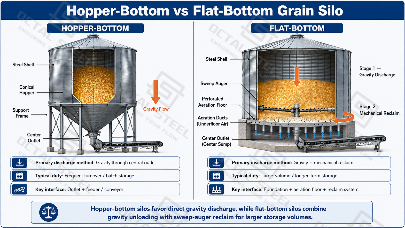
A hopper-bottom grain silo combines a cylindrical storage body with an elevated conical bottom supported by a steel frame. During unloading, grain moves through the hopper toward the central outlet mainly by gravity, reducing the amount of material that requires mechanical reclaim.
This configuration is generally suitable for batch storage, frequent grain turnover and process applications that require regular or near-complete silo emptying.
The final configuration should consider grain flow characteristics, fines content, required outlet size, supporting height, hopper surface and downstream conveyor arrangement. Hopper angle alone does not determine whether discharge will remain stable.
Flat-Bottom Grain Silo
A flat-bottom grain silo supports the cylindrical shell and stored grain on a reinforced-concrete foundation. This arrangement is generally suitable for larger inventories and longer-term bulk grain storage.
During unloading, the freely flowing grain is normally discharged first through the center or floor outlets. A sweep auger or other mechanical reclaim system then transfers the remaining grain toward the discharge point.
The flat floor, aeration channels, discharge openings, sweep-auger operating area and anchor layout should be coordinated before foundation construction.
Configuration Comparison
| Configuration | Structural Arrangement | Normal Unloading Method | Suitable Storage Duty | Main Design Control |
|---|---|---|---|---|
| 45° Hopper Bottom | Cylindrical silo elevated above a conical hopper | Gravity flow through a central outlet | Batch storage and frequent turnover | Grain flow, outlet size, support height and feeder interface |
| 60° Hopper Bottom | Elevated silo with a steeper conical hopper | Gravity flow through a central outlet | Materials requiring a steeper flow surface | Hopper load, outlet clearance and support-frame geometry |
| Flat Bottom | Cylindrical shell supported at foundation level | Center discharge followed by mechanical reclaim | Large-volume or longer-term storage | Foundation, aeration floor, outlet layout and reclaim coverage |
Grain Silo Size and Capacity Range
The table below summarizes the available grain silo series by nominal capacity, silo diameter, total height, cylindrical shell height, geometric volume and calculated storage capacity.
The listed capacities are reference values based on the bulk-density basis stated in the product data. Actual working capacity should be recalculated according to the confirmed grain type, usable filling volume, bulk density and normal operating level.
| Nominal Series | Silo Diameter | Total Silo Height | Cylindrical Shell Height | Geometric Volume | Catalog Maximum Capacity |
|---|---|---|---|---|---|
| 100 T | 4.50 m | 12.53 m | 7.91 m | 150 m³ | 112 t |
| 300 T | 6.417 m | 17.33 m | 11.27 m | 418 m³ | 313 t |
| 500 T | 8.25 m | 18.87 m | 11.27 m | 718 m³ | 538 t |
| 1,000 T | 10.084 m | 24.73 m | 15.75 m | 1,468 m³ | 1,101 t |
| 1,500 T | 11.90 m | 27.27 m | 16.87 m | 2,231 m³ | 1,673 t |
| 2,000 T | 13.75 m | 20.87 m | 16.87 m | 2,701 m³ | 2,026 t |
| 3,000 T | 16.50 m | 22.50 m | 17.99 m | 4,186 m³ | 3,139 t |
| 5,000 T | 20.10 m | 25.74 m | 20.23 m | 7,082 m³ | 5,311 t |
| 10,000 T | 27.50 m | 29.98 m | 22.47 m | 14,918 m³ | 11,189 t |
| 15,000 T | 32.085 m | 31.23 m | 22.47 m | 20,662 m³ | 15,496 t |
Download:Grain Silo Size, Capacity and Configuration Guide
How Grain Silo Capacity Is Calculated
A grain silo should not be selected from nominal tonnage alone. The actual amount of grain that can be stored depends primarily on usable storage volume and the bulk density of the confirmed grain.
Working Storage Capacity ≈ Usable Storage Volume × Grain Bulk Density
The geometric volume shown in the specification table represents the calculated internal space of the silo. The normal working inventory may be lower because clearance is required below the roof and filling equipment, while floor systems, hopper geometry and residual grain also affect usable storage volume.
Capacity Calculation Table
| Capacity Item | Meaning | Effect on Stored Grain Capacity |
|---|---|---|
| Geometric Volume | Total calculated internal volume of the silo | Provides the initial volume reference |
| Usable Storage Volume | Internal volume available below the normal high-level limit | Used to calculate normal working inventory |
| Grain Bulk Density | Mass of grain contained in one cubic metre | Converts usable volume into stored tonnes |
| Roof Clearance | Space maintained below the roof and filling equipment | Reduces the volume available for grain |
| Bottom and Reclaim Volume | Space occupied by the hopper, floor ducts or reclaim equipment | Changes usable volume and residual inventory |
| Residual Grain | Grain remaining after the normal unloading sequence | Reduces the quantity available for routine turnover |
Download:Grain Silo Capacity Calculation and Project Selection Guide
The standard silo series generally uses wheat with a reference bulk density of 0.75 t/m³ as a capacity calculation basis. For the 60° hopper-bottom product series, the catalog reference capacity uses 0.50 t/m³.
These values are calculation references only. They do not mean that every wheat lot has exactly the same bulk density or that every 60° hopper-bottom silo stores material with a density of 0.50 t/m³.
Actual capacity should always be confirmed according to the stored grain and project operating conditions.
Grain Silo Working Principle and Main Structure
A grain silo operates as part of an integrated grain storage and material-handling system rather than as an isolated steel container.
The silo body stores the grain, while receiving, cleaning, drying where required, conveying, aeration, monitoring and unloading systems control the material throughout the complete storage cycle.
How a Grain Silo Works
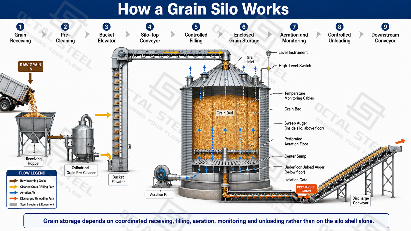
The complete operating sequence can be summarized as:
Grain Receiving → Pre-Cleaning → Optional Drying → Elevating & Conveying → Controlled Filling → Grain Storage → Aeration & Monitoring → Controlled Unloading
Two different capacities should be confirmed at the beginning of the project:
Storage Capacity – MT: How much grain the system needs to store.
Handling Capacity – TPH: How many tonnes per hour the system must receive, clean, dry, convey or discharge.
A project with 10,000 MT of storage and 100 TPH handling capacity can require very different conveying and electrical equipment from another 10,000 MT project designed for 500 TPH.
1. Grain Receiving and Pre-Cleaning
Incoming grain is transferred from the receiving point or receiving pit to the cleaning system. A pre-cleaner removes large impurities, small foreign material and part of the free dust before grain enters the storage route.
Pre-cleaning reduces the quantity of fines entering the silo, helps maintain more uniform airflow through the stored grain and reduces impurity accumulation around conveying equipment, aeration floors and discharge points.
The receiving system should be selected according to:
• Receiving method: Truck / Rail / Port
• Required receiving capacity, TPH
• Number of unloading points
• Grain impurity condition
• Dust-control requirements
2. Grain Drying System
Not every grain silo project requires a dryer. The need for grain drying should be evaluated according to the incoming grain moisture, target storage moisture and required process capacity.
The main parameters required for dryer selection are:
Drying Parameters Table
| Design Parameter | Required Information | Why It Matters |
|---|---|---|
| Incoming Moisture | Moisture content of grain entering the dryer | Defines the initial drying condition |
| Target Moisture | Required grain moisture after drying | Defines the required moisture reduction |
| Required Throughput | Required drying capacity in TPH | Determines dryer size and process capacity |
| Heat Source | Natural gas, LPG, diesel, biomass, steam or other confirmed source | Affects burner and heat-system configuration |
| Ambient Conditions | Ambient temperature, humidity and grain inlet temperature | Affect actual drying duty and airflow requirement |
For example, 100 TPH at 22% → 14% moisture reduction does not represent the same drying duty as 100 TPH at 18% → 14%.
The burner, airflow, heat system, dust-control arrangement and power demand must therefore be selected according to the complete drying duty rather than throughput alone.
Aeration does not replace dedicated grain drying when incoming moisture is above the required storage condition.
3. Grain Handling and Conveying System
After receiving, cleaning or drying, grain is transferred to the selected silo through vertical and horizontal conveying equipment.
Typical equipment includes:
• Bucket Elevator
• Chain Conveyor
• Belt Conveyor
• Screw Conveyor
• Grain Distributor
Equipment selection depends on the complete conveying duty rather than equipment name alone.
Grain Handling Selection Table
| Selection Parameter | Engineering Consideration |
|---|---|
| Handling Capacity | Required receiving, conveying or discharge capacity in TPH |
| Horizontal Length | Defines conveyor length and drive requirements |
| Lift Height | Defines bucket-elevator lifting duty and tower height |
| Motor & Gearbox | Selected according to equipment duty, operating conditions and project specification |
| Chain / Belt | Selected according to grain type, capacity and conveying equipment |
| Sensors | May include speed, misalignment, blockage and bearing-temperature monitoring |
| Dust Control | Transfer points and enclosed equipment may require dust collection according to project conditions |
The receiving, cleaning, drying and conveying systems should be capacity-matched so that one item of equipment does not become the bottleneck of the complete process.
4. Controlled Unloading
Grain enters the silo through the roof inlet and forms a bulk mass inside the cylindrical storage body.
The filling rate must remain within the rated capacity of the bucket elevator, conveyor, inlet and level-control system.
Continuous level measurement can provide normal inventory information, while an independent high-level alarm or switch can stop upstream equipment before overfilling occurs.
The inlet position and grain-distribution arrangement should also be coordinated with silo diameter, structural design and aeration layout to avoid excessive grain peaking or uncontrolled long-term eccentric filling.
5. Grain Storage, Aeration and Monitoring
After filling, the galvanized steel enclosure protects the stored grain from direct rainwater and external contamination, but it cannot correct unsuitable incoming grain conditions.
Grain moisture, temperature, cleanliness and insect condition should therefore be considered before long-term storage.
Aeration System
Aeration fans move air through foundation ducts, perforated flooring or other designed airflow channels and upward through the stored grain.
Aeration is mainly used to:
• Control grain temperature
• Reduce temperature differences
• Limit moisture migration
• Support stable storage conditions
Typical equipment may include:
• Aeration fan
• Air duct
• Perforated floor
• Roof vent
• Exhaust fan where required
Temperature Monitoring
Temperature cables installed at selected positions inside the silo monitor changes in the grain mass and help identify developing hot spots or abnormal temperature trends.
Typical components include:
• Temperature cables
• Junction boxes
• Monitoring unit
• PLC or software interface where required
Optional Fumigation System
Where fumigation is required by the customer’s grain-management procedure, the storage system can be provided with suitable project-specific fumigation interfaces.
Typical components may include:
• Fumigation piping
• Gas distribution arrangement
• Recirculation arrangement
• Required sealing provisions
The final configuration depends on the grain type, storage-management procedure and applicable project requirements.
6. Controlled Unloading
During unloading, hopper-bottom grain silos normally direct grain toward the central outlet by gravity.
Flat-bottom silos first discharge the freely flowing central inventory through floor or center outlets. A sweep auger or other reclaim system then transfers the remaining grain toward the discharge point.
In both configurations, the outlet transition, discharge gate, reclaim equipment and downstream conveyor should be aligned and sized as one coordinated discharge system.
Main Structure and Materials
| Component | Primary Function | Grain-Service Design Consideration |
|---|---|---|
| Corrugated Sidewall Sheets | Form the cylindrical storage enclosure | Sheet thickness and ring arrangement depend on stored-grain pressure and environmental loads |
| Vertical Stiffeners | Transfer vertical loads to the base and foundation | Stiffener sections and connections must remain continuous through the wall rings |
| Conical Roof | Encloses the silo and supports roof-mounted equipment | Filling, ventilation and instrument penetrations require weather-resistant sealing |
| Roof Support Members | Transfer roof and equipment loads to the shell | Arrangement must account for conveyors, distributors and access loads |
| Bolted Wall Joints | Connect prefabricated sheets into complete wall rings | Hole alignment, overlap direction, sealing and controlled tightening are required |
| Hopper or Flat Floor | Supports grain and directs it toward unloading equipment | Geometry must match grain flow and the selected reclaim method |
| Base Ring and Anchors | Connect the steel structure to the foundation | Anchor positions must correspond to stiffener and shell-load paths |
| Support Frame | Elevates a hopper-bottom silo | Columns and bracing transfer hopper, grain and equipment loads to the foundation |
| Access System | Provides inspection and maintenance access | Ladders, platforms, manholes and doors must avoid interference with conveyors and instruments |
| Sealing Components | Limit rainwater, dust and uncontrolled air leakage | Roof joints, wall laps, manholes and equipment interfaces require continuous sealing |
| Aeration Floor / Air Duct | Provide the designed airflow path through stored grain | Must coordinate with the foundation, discharge openings and aeration fan layout |
| Discharge Gate | Control grain flow from the silo | Outlet size should match the required discharge capacity and downstream equipment |
| Sweep Auger | Recover residual grain from flat-bottom silos | Coverage and outlet arrangement affect final reclaim performance |
Grain Silo Design Inputs and System Coordination
A grain silo cannot be selected from nominal capacity alone.
The required system configuration depends on the stored grain, working inventory, storage period, incoming grain condition, required handling capacity, environmental loads, electrical conditions and civil interfaces.
Grain Silo Design Inputs
| Design Input | Engineering Significance | Effect on System Configuration |
|---|---|---|
| Grain Type & Bulk Density | Define stored mass, flow behavior and airflow resistance | Affect usable capacity, structural loading, aeration and discharge arrangement |
| Required Working Capacity | Defines the normal operating inventory | Determines preliminary silo diameter, height and number of storage cells |
| Receiving Capacity, TPH | Defines incoming grain-handling duty | Affects receiving pit, cleaner, bucket elevator and conveyor selection |
| Discharge Capacity, TPH | Defines required silo unloading rate | Affects outlet size, reclaim equipment and downstream conveyors |
| Incoming Moisture & Temperature | Indicate whether incoming grain is suitable for storage | Affect drying requirements, aeration duty and monitoring coverage |
| Storage Duration | Defines the required period of grain-condition management | Influences aeration, monitoring, sanitation and inventory-turnover planning |
| Site & Environmental Conditions | Include wind, seismic action, snow and ambient conditions | Affect shell, stiffeners, anchors, foundation and general layout |
| Power Supply | Defines available voltage and frequency | Affects motors, MCC, VFD and electrical-control configuration |
| Geotechnical Information | Defines soil conditions and foundation assumptions | Affects foundation type, dimensions and civil design |
| Future Expansion | Defines future silo or equipment requirements | Affects reserved interfaces, layout and conveying routes |
Changing the stored grain after the silo has been designed can alter both capacity and structural loading. A silo configured for wheat should not automatically be used for a denser grain or another bulk material without reviewing its bulk density, flow characteristics, aeration demand and discharge behavior.
System Coordination
The silo body and auxiliary equipment should be developed as one coordinated grain-storage system.
The bucket-elevator discharge height determines the silo-top conveyor elevation. The conveyor route affects roof loading and filling-inlet positions. The selected bottom arrangement determines outlet elevation and downstream conveyor layout. Aeration ducts and discharge openings also affect foundation geometry.
These interfaces should therefore be confirmed before fabrication and civil construction.
Late changes to conveying routes, outlet positions, aeration ducts or reclaim equipment can create conflicts with roof members, anchors, access platforms and foundation openings.
Grain Silo Electrical and Automation System
Electrical control and automation coordinate the operation of receiving, cleaning, drying, conveying, storage and discharge equipment.
The level of automation should be selected according to project size, process requirements, local electrical standards and the customer’s operating philosophy.
Electrical & Automation Table
| Equipment / Function | Application |
|---|---|
| PLC | Process logic and sequential equipment control |
| HMI | Operator interface and system-status display |
| MCC | Motor Control Center for conveying and auxiliary equipment |
| VFD | Variable-frequency control where speed adjustment is required |
| Level Sensor | Monitor grain level and support filling control |
| Speed Sensor | Monitor elevator or conveyor operating speed |
| Belt Misalignment Sensor | Detect abnormal belt tracking or deviation |
| Blockage Sensor | Detect material blockage in conveying equipment |
| Bearing Temperature Sensor | Monitor abnormal bearing-temperature conditions |
| Equipment Interlock | Coordinate equipment start and stop sequences |
| Alarm & Emergency Stop | Provide abnormal-condition warning and emergency shutdown |
Structural and Operational Safety
Safe operation depends on maintaining the filling and unloading conditions used in the structural design.
Grain should be introduced and withdrawn through the confirmed locations because uncontrolled eccentric filling or discharge can change the pressure distribution acting on the silo wall.
Conveyors, aeration fans and reclaim equipment should be safely isolated before internal inspection or maintenance.
Grain handling can also generate combustible dust. The required protection measures should be determined according to project hazard assessment, dust characteristics, equipment arrangement and applicable regulations.
Depending on the project, measures may include:
• Enclosed transfer points
• Dust extraction
• Ignition-source control
• Grounding
• Bearing-temperature monitoring
• Speed and belt-misalignment monitoring
• Equipment interlocks
• Explosion relief or isolation where required
• Emergency stop
These provisions are project-specific. A general statement that every grain silo is universally “explosion-proof” should be avoided.
Grain Quality Protection During Storage
A steel silo provides a controlled enclosure, but stored grain remains a biological material whose condition can change during storage.
Moisture control therefore begins before the grain enters the silo and continues through cleaning, drying where required, aeration, monitoring, pest management and complete unloading.
Grain Storage Condition Table
| Storage Condition | Effect on Stored Grain | Required System Response |
|---|---|---|
| Excessive Incoming Moisture | Reduces safe storage time and increases mold or heating risk | Confirm moisture before storage and coordinate drying where required |
| Uneven Grain Temperature | Drives moisture migration between warmer and cooler zones | Use aeration and temperature monitoring to reduce temperature differences |
| High Fine Content | Restricts airflow and creates dense local zones | Improve pre-cleaning and control filling distribution |
| Roof-Space Condensation | Returns moisture to the upper grain layer | Maintain suitable roof ventilation and temperature management |
| Local Temperature Increase | May indicate biological or insect activity | Review sensor trends, sample the grain and operate aeration when conditions permit |
| Insect Activity | Reduces quality and may create local heating | Maintain sanitation and monitoring; use project-specific fumigation or other approved treatment where required |
| Residual Grain | Retains contaminated material between storage batches | Complete unloading and clean internal surfaces and reclaim zones |
| Blocked Aeration Path | Produces uneven airflow and untreated grain zones | Inspect fans, ducts, perforated floors and grain distribution |
| Excessive Storage Duration | Increases exposure to quality deterioration | Match monitoring and turnover planning to the intended storage period |
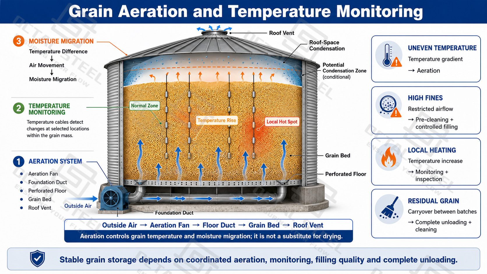
Aeration performance depends on both grain condition and outside-air temperature and humidity, because unsuitable air can increase moisture migration instead of improving storage stability. Temperature cables indicate changes only near their sensing points, so the readings must be assessed together with grain sampling, fan performance, storage duration and safe visual or odor-related inspection. The silo enclosure also requires regular checks of roof seals, vents, internal surfaces and reclaim areas, since water leakage, blocked airflow paths or residual grain can reduce the effectiveness of an otherwise correctly designed grain storage system.
Applications and Process Integration
Farm and Cooperative Grain Storage
Farm and cooperative grain silos are used to store harvested grain before sale, processing or transfer.
The silo system can be connected to receiving pits, pre-cleaners, bucket elevators and truck-loading conveyors according to the local operating process.
Grain Processing and Feed Plants
Flour mills, feed plants, starch-processing facilities, corn-processing plants and other agricultural processing operations use grain silos as raw-material storage and process buffers.
Storage cells can separate grain by type or grade and feed downstream processing equipment at the required rate.
Central Grain Reserves
Central and commercial grain reserves generally require coordinated storage capacity, aeration, temperature monitoring, inventory rotation and multi-silo conveying routes.
Multiple silos can share elevator towers and transfer conveyors according to the project layout.
Port and Bulk Handling Terminals
Port, rail and inland bulk terminals often require higher receiving and conveying capacities to support rapid unloading, storage and dispatch.
System design should therefore consider high-capacity elevators and conveyors, dust-control requirements, transfer routing and maintenance access.
Grain Silo Project Delivery, Installation and Commissioning
OCTAL STEEL grain silo projects can progress from factory preparation and packing to transportation, site receiving, erection and commissioning support according to the confirmed contractual scope.
The complete delivery process should coordinate silo structures, conveying equipment, auxiliary systems and project interfaces rather than treating the silo as an isolated steel shell.
Packing and Shipment
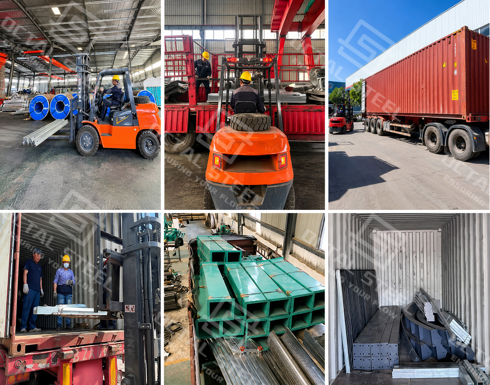
Prefabricated silo components are sorted and packed according to component type, dimensions and installation sequence before shipment.
Corrugated wall sheets, structural members, conveying components, fasteners and auxiliary equipment should remain clearly identified so that they can be checked and distributed efficiently after arrival at site.
Shipment planning should also consider lifting access, protection of galvanized surfaces and the sequence in which components are required during installation.
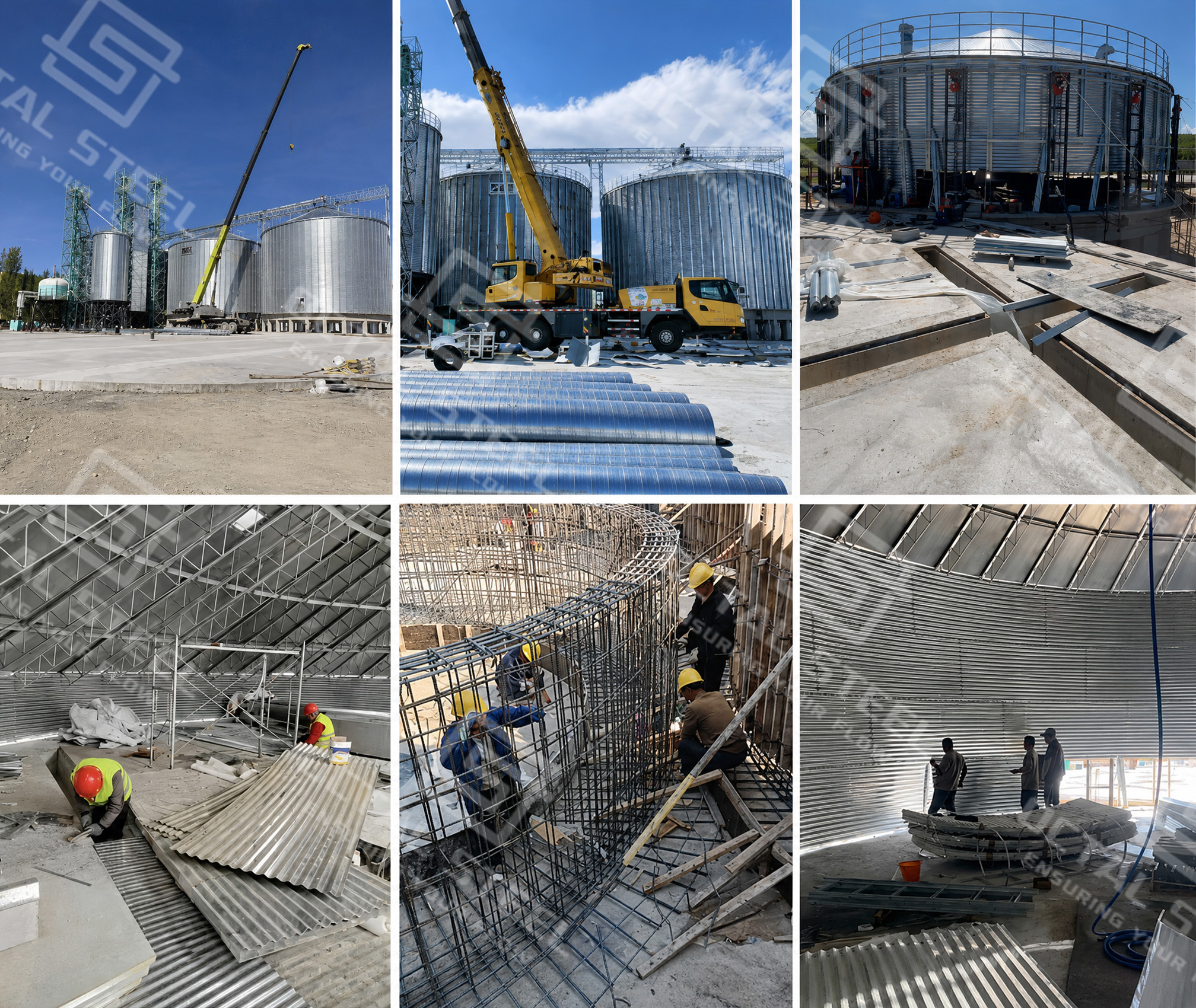
Grain Silo Site Assembly
After materials arrive at site, installation normally begins with verification of foundation dimensions, anchor positions and major equipment interfaces.
Corrugated wall sheets, vertical stiffeners, roof structures, support components and conveying equipment are then installed according to the approved layout and erection procedure.
For hopper-bottom silos, the steel support frame, hopper and cylindrical shell must remain correctly aligned.
For flat-bottom silos, the shell, foundation, aeration openings and floor-level discharge interfaces should be coordinated before completing the lower structure.
Project Scope Options
The available project service scope may include:
• Equipment Supply
• Installation Supervision
• Installation Support
• Commissioning Support
• Operator Training
• Turnkey / EPC scope subject to project-specific confirmation
Civil works, local labor, lifting equipment, utilities, travel, accommodation and other site responsibilities should be clearly defined before final quotation.
Information Required for Grain Silo Quotation
To prepare a technically meaningful grain silo quotation, the following project information should be confirmed as far as possible.
If major technical parameters remain unknown, the initial offer should normally be treated as a budgetary proposal rather than a final executable quotation.
RFQ Information Table
| No. | Information Required | Typical Confirmation |
|---|---|---|
| 1 | Grain Type | Wheat / Corn / Rice / Soybeans / Other |
| 2 | Bulk Density | t/m³ or kg/m³ |
| 3 | Total Storage Capacity | Total required MT |
| 4 | Capacity per Silo | Required MT per silo |
| 5 | Number of Silos | Required quantity |
| 6 | Silo Type | Flat Bottom / Hopper Bottom |
| 7 | Receiving Capacity | Required TPH |
| 8 | Discharge Capacity | Required TPH |
| 9 | Receiving Method | Truck / Rail / Port / Other |
| 10 | Incoming Moisture | % |
| 11 | Target Moisture | % if drying is required |
| 12 | Dryer Required | Yes / No |
| 13 | Heat Source | Natural Gas / LPG / Diesel / Biomass / Steam / Other |
| 14 | Cleaning Requirement | Pre-cleaner / Magnet / Dust Collection / Other |
| 15 | Aeration & Monitoring | Aeration / Temperature Monitoring / Level Monitoring / Fumigation |
| 16 | Final Discharge Destination | Truck Loading / Processing Line / Other |
| 17 | Project Location | Country and site location |
| 18 | Environmental Conditions | Wind / Seismic / Snow / Ambient Temperature |
| 19 | Power Supply | Voltage / Frequency |
| 20 | Soil / Geotechnical Information | Soil bearing capacity or geotechnical report where available |
| 21 | Civil & Installation Responsibility | Customer / Supplier / To Be Confirmed |
| 22 | Required Project Scope | Equipment Supply / Complete System / Installation / Turnkey / EPC |
FAQ
Q1: How is the grain silo capacity determined?
A1:The actual storage capacity depends on the usable storage volume and grain bulk density. Different grains have different densities, so the same silo volume may store different quantities of wheat, corn, rice or soybeans. The final capacity should be confirmed according to the grain type and project requirements.
Q2: How to choose between a flat-bottom silo and a hopper-bottom silo?
A2: Hopper-bottom silos are suitable for frequent turnover and gravity unloading. Flat-bottom silos are generally preferred for larger storage capacity and longer-term storage, with mechanical reclaim systems for remaining grain. The selection depends on storage capacity, grain characteristics and operating requirements.
Q3: Can OCTAL STEEL provide a complete grain silo system?
A3: Yes. According to the project scope, OCTAL STEEL can coordinate: Grain silo body/Receiving and cleaning system/Drying system (if required)/Conveying equipment/Aeration and monitoring system/Electrical control system. The final configuration is based on the customer’s process requirements.
Q4: What information is required for a grain silo quotation?
A4: The main information includes: Grain type and bulk density/Storage capacity and number of silos/Silo type (flat-bottom or hopper-bottom)/Receiving and discharge capacity (TPH)/Moisture condition and drying requirement/Project location and required supply scope. With these details, we can provide a more accurate technical proposal and quotation.