Your Responsible Supplier Partner for Oil and Gas Products.
Pipe Making Machine
Recent Products
Rencent Articles
Pipe Making Machine
Process coverage: Complete solutions for LSAW (JCOE) and SSAW pipe making lines
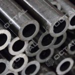
Pipe range: OD 508–1626 mm with configurations matched to different wall thickness and grade requirements
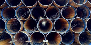
Quality control: UT, X-ray, hydrotest, and full inspection paths for project-grade production
Line engineering: Integrated design for forming, welding, handling, finishing, and utilities
Turnkey support: From technical proposal and equipment matching to commissioning and operator training
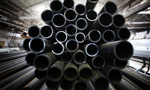
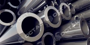
A pipe making machine is a complete production system used to manufacture welded steel pipes for oil & gas, water transmission, and structural applications. A modern steel pipe making machine line must combine forming, welding, inspection, finishing, and material handling into one coordinated process. As a pipe making machine supplier, Octal Steel provides complete line solutions for both LSAW (JCOE) and SSAW processes, from project-scale pilot lines to high-volume mills producing 200,000 t/year and above.
What is a Pipe Making Machine
A pipe making machine converts flat steel plate or coiled strip into finished welded steel pipe through a defined sequence of forming, welding, sizing, inspection, and finishing operations. The three main process types in industrial use are LSAW (longitudinal submerged arc welded), SSAW (spiral submerged arc welded), and ERW (electric resistance welded). Each uses a different raw material input, forming method, and weld configuration, and each is suited to a different combination of pipe diameter, wall thickness, grade, and application.
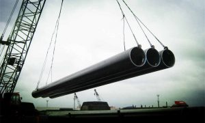
For oil and gas transmission, piling, and offshore structural applications where wall thickness above 20 mm and grades up to X120 are required, LSAW and SSAW are the standard choices. ERW covers smaller diameters and lighter walls for water, gas distribution, and structural hollow sections. A complete pipe making machine line includes not only the forming and welding equipment but also the full auxiliary, handling, inspection, and automation infrastructure that determines actual production output and pipe quality.
In addition to forming and welding equipment, a complete pipe making machine line also depends on factory automation, inspection systems, and auxiliary handling infrastructure to achieve stable output and qualified pipe quality.
Types of Pipe Making Machine
The most common pipe machine solutions for large-diameter welded pipe production are LSAW and SSAW lines.
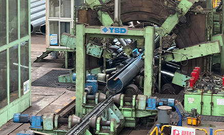
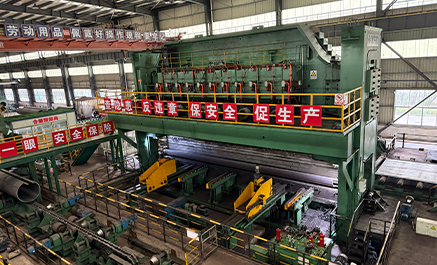
LSAW Pipe Making Machine (JCOE Technology)
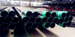
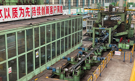
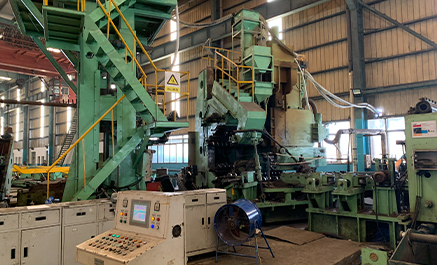
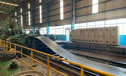
The JCOE process uses flat steel plate as raw material. The plate is progressively pressed into a J-shape, then C-shape, then closed into an O-shape (open pipe shell), pre-welded, internally and externally submerged arc welded, and then mechanically expanded to final OD tolerance. Each step is a separate machine station. LSAW is the preferred steel pipe making machine route for large-diameter, thick-wall, high-grade line pipe where dimensional precision and full-penetration weld integrity are required for API 5L PSL2 qualification. For high-grade line pipe projects, working with an experienced steel pipe making machine manufacturer helps ensure correct line configuration, inspection scope, and process stability.
Typical applications: oil and gas transmission pipelines, offshore riser and piling pipe, high-pressure structural pipe, subsea pipeline. 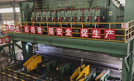
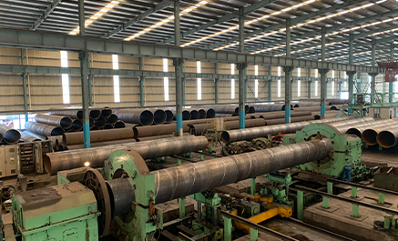
SSAW Pipe Making Machine (Spiral Welded Pipe)
The SSAW process uses coiled strip as raw material. The strip is formed into a helix at an adjustable angle and continuously welded with a spiral submerged arc weld seam. By changing the forming angle, a single strip width can produce a range of pipe diameters. SSAW lines run at high throughput and are suited to large-diameter, medium-pressure pipe where flexible OD coverage and output rate take priority over heavy wall capability. For large-volume water or structural projects, a qualified pipe making machine supplier should be able to provide both equipment matching and full process solution support.
Typical applications: long-distance water transmission, drainage infrastructure, wind tower foundations, sheet piling.
For buyers comparing different pipe machine routes, the table below highlights the main differences between LSAW and SSAW pipe making machine lines in terms of raw material, forming method, capability, and project suitability.
LSAW vs SSAW Pipe Making Machine Comparison
| Item | LSAW (JCOE) | SSAW (Spiral) |
|---|---|---|
| Raw Material | Steel plate | Steel coil (strip) |
| Forming Method | JCOE progressive press forming | Continuous spiral forming |
| Production Mode | Batch production (discrete stations) | Continuous production line |
| Pipe OD Range | 508 – 1422 mm | 508 – 1626 mm |
| Wall Thickness Capability | Thicker walls (up to 60 mm) | Medium thickness (typically ≤25.4 mm) |
| Steel Grade Range | API 5L up to X100 / X120 | API 5L up to X70 / X80 |
| Dimensional Accuracy | High precision (mechanical expansion) | Moderate precision |
| Welding Quality | Higher weld consistency and integrity | Good, but depends on forming stability |
| Production Efficiency | Lower (multi-step process) | Higher (continuous line) |
| Typical Applications | Oil & gas transmission, offshore, high-pressure pipelines | Water transmission, piling, structural use |
Typical LSAW Pipe Making Machine Configuration
The table below provides a quick overview of a typical LSAW pipe making machine configuration, including the core process stages, key equipment, and supported functions.
| Process Stage | Key Equipment | Main Function & Standards Supported |
|---|---|---|
| Raw Material Inspection | Automatic plate UT scanner + laser marking system | 100% defect detection, full traceability (API 5L, EN 10160) |
| Edge Preparation | Plate edge milling machine + edge pre-bending machine | Stable weld bevel geometry and correct edge curvature before forming |
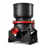
| Forming | JCOE forming machine | Progressive press forming: J-shape → C-shape → O-shape; OD 508–1422 mm |
| Pre-Welding | Continuous pre-welder with 9-roll closing device | Continuous CO₂ gas-shielded tack welding of the open seam |
| Welding | Internal and external multi-wire SAW welding machines | Full-penetration welds qualified to API 5L / ISO 3183 |
| Expansion & Sizing | Mechanical pipe expander | Corrects OD tolerance and improves dimensional consistency after welding |
| NDT & Quality Control | Weld UT + weld X-ray + bevel MPI + pipe-end UT | Multi-stage inspection route for PSL1 / PSL2 and third-party projects |
| Hydrostatic Testing | 4000 T hydrostatic testing machine | Full-length pressure qualification and reject routing |
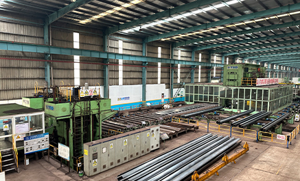
| Finishing | End-facing and beveling machine + straightening machine + finishing machine | Ready for field welding, shipment, or coating line integration |
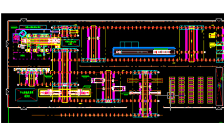
LSAW (JCOE) Pipe Making Machine — Full Line Configuration
The full JCOE line divides into four functional groups: main process equipment, auxiliary and material handling, inspection and NDT, and automation and control.
Main Process Equipment
| No. | Equipment | Qty | Function |
|---|---|---|---|
| 1 | Plate Edge Milling Machine | 1 set | Mills both plate edges to the required weld bevel geometry; maintains ±0.1 mm edge tolerance for consistent SAW penetration. |
| 2 | Edge Pre-bending Machine | 1 set | Bends plate edges to the required curvature radius before forming; prevents flat zones at the pipe seam after closing. |
| 3 | JCOE Forming Machine | 1 set | Progressive press forming: J-shape → C-shape → O-shape (closed pipe shell); handles OD 508–1422 mm, WT 6–60 mm. |
| 4 | Continuous Pre-welder | 1 set | CO₂ gas-shielded continuous tack welding of the open seam; 9-roll closing device holds the shell in position during welding. |
| 5 | Pipe Internal Welding Machine | 2 sets | Multi-wire submerged arc welding of the internal seam; fixed boom, pipe moves on carriage; automatic flux recovery. |
| 6 | Pipe External Welding Machine | 2 sets | Multi-wire submerged arc welding of the external seam; stationary welding head, pipe travel at welding speed; automatic seam tracking and flux recovery. |
| 7 | Mechanical Pipe Expander | 1 set | Step-by-step mechanical expansion along the full pipe length; corrects OD tolerance after welding and improves dimensional consistency. |
| 8 | End-facing and Beveling Machine | 1 set | Machines both pipe ends to bevel angle required by welding specification (30°±5°); pre-flushing before entry. |
| 9 | Hydrostatic Testing Machine (4000 T) | 1 set | Full-length hydrostatic pressure test; automatic seal, fill, pressurize, hold, drain; rejects piped out directly. |
| 10 | Pipe Straightening Machine | 1 set | Multi-roll rotary straightening for structural pipe route; straightness ≤1:1000. |
| 11 | Pipe Finishing Machine | 1 set | Final OD sizing and rounding for structural pipe; pipe-end geometry correction. |
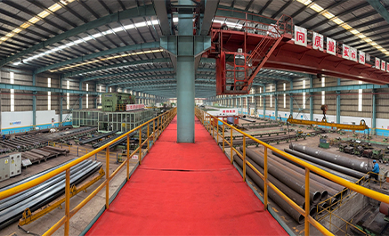
Auxiliary Equipment & Material Handling
Plate feeding and conveying: Plate loading roller table, transverse feeding device, roller tables through the plate inspection zone, edge milling waiting area, pre-bender waiting area, and forming machine waiting area — each section independently driven with PLC interlocks to the main line.
Pipe transfer and storage: 42 sets of four-wheel transfer cars and 7 sets of eight-wheel transfer cars on approximately 1,100 m of track handle all lateral pipe movement between stations. 437 sets of independent V-type roller tables provide longitudinal pipe travel. Approximately 546 m of pipe storage stands, 28 end pipe stoppers, and 54 side pipe stoppers complete the handling layout.
Welding support: 6 welding cars (3 internal, 2 external, 1 X-ray) on 318 m of dedicated welding car rail. Run-on/run-off tab welding tooling (4 sets) at the plate receiving area ensures weld quality at both pipe ends.
Cleaning and dust removal: External cleaning equipment after pre-welding, internal surface cleaning equipment after pre-welding, internal slag cleaning equipment after internal welding, and external slag cleaning equipment after external welding — each with integrated dust collection.
Water and expansion systems: Expander emulsion treatment system, pre-expansion flushing, post-expansion flushing, central cooling circulating water system, 5 sets of water treatment facilities for hydrostatic test water, UT coupling water, and cooling circuits; compressed air supply system 2×15 m³/min (one duty, one standby).
Pipe-end finishing: 2 sets of pipe-end external weld grinding machines, 2 sets of pipe-end internal weld grinding machines, 2 sets of pipe-end rounding machines, 1 set of weighing and length measuring device, 10 hydraulic pipe turners, 6 discharge stands (each comprising 4 stands).
Inspection & NDT Equipment
| Equipment | Qty | Coverage | Standard Basis |
|---|---|---|---|
| Plate Ultrasonic Inspection Machine | 1 set | 100% plate body before forming | API 5L, EN 10160 |
| Weld Ultrasonic Inspection Machine | 2 sets | Full-length weld seam, post-welding | API 5L PSL1/PSL2, ISO 3183 |
| Weld X-ray Inspection Machine | 2 sets | Full-length weld seam, post-UT | API 5L, ASME Section V |
| Pipe-end X-ray Inspection | Integrated | Both pipe-end weld zones | API 5L |
| Pipe-end Ultrasonic Inspection | Integrated | Pipe-end weld and body zone | API 5L PSL2 |
| Bevel Magnetic Particle Inspection | 1 set | Both bevel faces after beveling | ASTM E709 |
| Hydrostatic Testing Machine | 1 set | Full-length pressure hold | API 5L, ASME |
NDT sequence for the line pipe route: plate UT → post-welding weld UT → weld X-ray → pipe-end X-ray → hydrostatic test → post-hydrotest weld UT → second weld X-ray → bevel MPI → pipe-end UT. Each stage has a defined rejection path (cut-off, repair weld, or re-inspect). This sequence supports API 5L PSL2 data book compilation and third-party certification.
Automation & Control
Factory automation is a critical part of the full JCOE line, covering PLC-based control, welding parameter logging, transfer coordination, and inspection data collection. Key functions: roller table and transfer car interlocks, welding parameter monitoring and data logging, NDT result collection, hydrostatic test cycle control and reporting, weighing and length measurement recording, and marking and printing coordination. The system supports 4-crew 3-shift continuous operation with approximately 6,000 effective production hours per year.
Installed electrical load for the full JCOE line: approximately 15,500 kW at 380 V / 50 Hz, voltage fluctuation ≤±10%. Compressed air: 2×15 m³/min at 0.4–0.8 MPa.
LSAW (JCOE) Pipe Making Machine — Key Parameters
| Parameter | Specification |
|---|---|
| Pipe OD range | 508 – 1422 mm (20″ – 56″) |
| Wall thickness range | 6 – 60 mm (Q345); 6 – 43 mm (X70); 6 – 40 mm (X80); 6 – 32 mm (X100) |
| Pipe length | 8 – 12.2 m |
| Maximum single pipe weight | 26 t (1422 mm × 60 mm × 12.2 m) |
| Designed annual output | 200,000 t (line pipe 60% + structural pipe 40%) |
| Steel grade range | API 5L X42 – X120; structural yield strength ≤620 MPa |
| Applicable standards | API 5L / ISO 3183, ASME A106/A333, ASTM A53/A500, JIS G3444, GB/T 9711 |
| Welding method | Automatic multi-wire submerged arc welding (internal + external) |
| Effective working hours/year | ~6,000 h (4-crew, 3-shift; 14 days major overhaul/year) |
| Installed electrical load | ~15,500 kW |
| Compressed air supply | 2 × 15 m³/min; 0.4 – 0.8 MPa |
The following key parameters define the practical capability of a large-diameter steel pipe making machine line for project evaluation and equipment matching.
A typical large-diameter JCOE line is designed for:
• Pipe OD range: 508–1422 mm
• Wall thickness range: 6–60 mm
• Pipe length: 8–12.2 m
• Maximum single pipe weight: 26 t
• Designed annual output: 200,000 t
• Steel grade range: API 5L X42–X120
• Applicable standards: API 5L / ISO 3183, ASME, ASTM, JIS, GB
• Welding method: Automatic multi-wire submerged arc welding
• Effective working hours/year: approximately 6,000 h
• Installed electrical load: approximately 15,500 kW
• Compressed air supply: 2 × 15 m³/min at 0.4–0.8 MPa
Typical Product Range by Grade and OD
Based on the above production parameters, the following table shows the typical pipe size and wall thickness combinations achievable for different steel grades.
| OD (inch) | OD (mm) | Max WT X70 | Max WT X60 |
|---|---|---|---|
| 20″ | 508 | ≤16 mm | ≤20 mm |
| 24″ | 610 | ≤18 mm | ≤22 mm |
| 28″ | 711 | ≤20 mm | ≤25 mm |
| 32″ | 813 | ≤22 mm | ≤28 mm |
| 36″ | 914 | ≤25 mm | ≤30 mm |
| 40–48″ | 1016–1219 | ≤28 mm | ≤32 mm |
| 52–64″ | 1321–1626 | ≤30 mm | ≤35 mm |
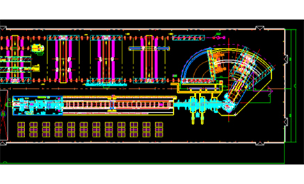
SSAW Pipe Making Machine — Line Configuration
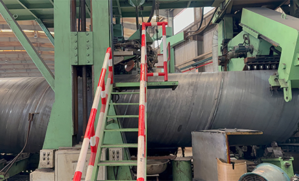
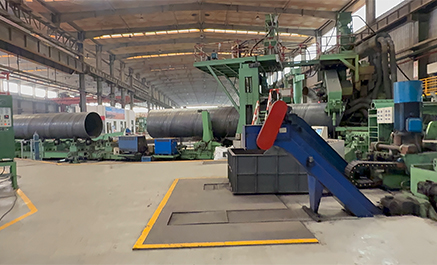
The SSAW line uses a continuous rear-pendulum forming process. Coiled strip feeds through a leveling and edge preparation section, is formed into a helix at the spiral forming machine, and is welded continuously with internal and external double-wire submerged arc welding.Compared with discrete LSAW stations, this type of pipe machine is better suited to continuous, high-throughput production.
The forming angle is externally adjustable, allowing OD 508–1626 mm to be produced from a single line. The full line divides into four functional sections.
Coil Preparation & Strip Joining Section
This section focuses on continuous strip feeding and coil-to-coil joining, ensuring uninterrupted production without stopping the main forming line.
| No. | Equipment | Qty | Function |
|---|---|---|---|
| 1 | Uncoiler with material preparation car | 1 set | Supports and uncoils strip coil (OD φ1200–2300 mm, max 40 t); material preparation car positions the coil for loading. |
| 2 | Coil end opener | 1 set | Separates the leading end of the coil and feeds it into the leveler. |
| 3 | Pinch and leveling machine | 1 set | Straightens the strip to flatness required for edge milling and forming; driven pinch rolls maintain constant strip tension. |
| 4 | Vertical roll device | 6 sets | Edge-guiding rolls that maintain lateral strip alignment through the feeding section. |
| 5 | Shear and butt weld unit | 1 set | Cuts the trailing end of the spent coil and welds it to the leading end of the next coil for continuous production. |
| 6 | Exit pinch machine | 1 set | Drives strip from the joining section into the accumulation and forming area. |
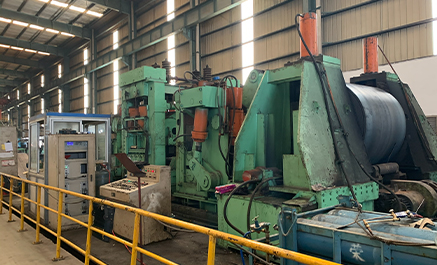
Spiral Forming & Welding Section
This section is the core of the SSAW pipe making machine, where strip forming, weld seam control, and continuous submerged arc welding are carried out.
| No. | Equipment | Qty | Function |
|---|---|---|---|
| 8 | Strip edge milling machine | 2 sets | Mills both strip edges to the required weld bevel; removes burrs, scale, and hardened gas-cut zones before forming. |
| 9 | Strip surface cleaning machine | 1 set | Brushes and removes surface scale and debris before the strip enters the forming machine. |
| 10 | Feed (delivery) machine | 1 set | Drives the strip into the forming machine at controlled feed speed (0.5–3 m/min). |
| 11 | Pre-bending and guide plate unit | 1 set | Pre-bends strip edges to prevent hard-edge cracking at the spiral weld seam. |
| 12 | Spiral forming machine | 1 set | Three-roll forming mill with externally adjustable forming angle (40°–80°); produces OD 508–1626 mm from strip width 1000–2000 mm; edge-positioning, externally controlled forming method. |
| 13 | Mobile centralizer | 1 set | Supports the pipe adjacent to the welding zone and maintains roundness during internal and external welding. |
| 14 | V-frame support | 1 set | Supports the pipe between the forming machine exit and the welding stations. |
| 15 | Internal and external welding unit | 1 set | Positions and guides the internal and external welding heads; connects to the welding power sources and flux system. |
| 16 | Welding power source AC/DC-1000SD (Lincoln) | 8 sets | Provides welding current for double-wire internal SAW and double-wire external SAW; 2 wires per side, total 4 welding arcs. |
| 17 | Flux recovery and supply unit | 1 set | Collects unused flux from internal and external welding, screens and recirculates it to the welding heads. |
| 18 | Strip butt weld car (Lincoln) | 1 set | Semi-automatic welding car for coil-change butt joints. |
| 19 | Internal and external automatic seam tracking system | 1 set | Real-time seam tracking for both internal and external SAW heads; maintains weld position accuracy during continuous forming. |
| 20 | Slag cleaning machine | 1 set | Removes welding slag from the external weld bead surface after the external welding station. |
Cut-to-Length & Material Handling Section
This section handles pipe cutting, transfer, and positioning, ensuring smooth flow of finished pipes between production and finishing stages.
| No. | Equipment | Qty | Function |
|---|---|---|---|
| 21 | Flying cut-off machine | 1 set | Cuts the continuously formed pipe to length while the line remains in motion; primary cut-off for standard lengths. |
| 22 | Plasma cutting machine | 1 set | Secondary cut-off for precision cutting and pipe-end dressing where flying cut-off tolerance is insufficient. |
| 23 | Rear bridge device | 1 set | Supports the pipe between the forming machine and the cut-off station; pivots to match the helical pipe exit angle. |
| 24 | Pipe transport car and rotation car | 1 set | Transfers cut pipes from the main forming area to the finishing area; rotation car repositions pipes for the weld grinding and inspection stations. |
| 25 | Pipe transverse transfer car | 12 sets | Moves pipes laterally between stations in the finishing area. |
| 26 | Rotating roller (lifting type) | 6 sets | Lifts and rotates pipe to the required orientation for weld grinding and inspection operations. |
| 27 | Rotating roller (fixed type) | 22 sets | Supports and rotates pipe at fixed stations in the finishing area. |
| 28 | Pipe receiver / dispatcher | 22 sets | Controlled pipe entry and exit at each station; prevents collision and controls pipe sequencing. |
| 29 | Pipe stopper | 66 sets | End-stop safety devices on roller tables and transfer car rails. |
| 30 | Drive conveyor roller table | 170 sets | Powered roller tables for longitudinal pipe movement through the finishing area. |
| 31 | Passive conveyor roller table | 6 sets | Unpowered support rollers at fixed positions. |
| 32 | Swing conveyor roller table | 4 sets | Pivoting roller sections that redirect pipe travel at section transitions. |
| 33 | Pipe storage stand | 8 sets | Finished pipe storage racks in the finishing area. |
Inspection & Finishing Section
This section ensures final pipe quality through grinding, hydrostatic testing, dimensional correction, and non-destructive inspection.
| No. | Equipment | Qty | Function |
|---|---|---|---|
| 34 | Internal weld grinding machine | 2 sets | Grinds the internal weld bead at both pipe ends to flush for pipe-end sealing and connection; removes weld reinforcement at the pipe-end zone. |
| 35 | External weld grinding machine | 2 sets | Grinds the external weld bead at both pipe ends; ensures the weld zone geometry meets beveling and coating requirements. |
| 36 | Cross-weld welding unit | 1 set | Welds and repairs the intersection of the spiral seam with the strip butt weld (cross weld); required where the coil-change butt weld crosses the spiral seam. |
| 37 | 3000 T hydrostatic test machine | 1 set | Full-length hydrostatic pressure test; automatic seal, fill, pressurize, hold, drain cycle; qualifies pipe to API 5L pressure test requirements. |
| 38 | Pipe-end expander | 1 set | Expands both pipe ends to correct OD tolerance in the end zone; ensures pipe-end roundness meets field welding requirements. |
| 39 | Beveling machine | 1 set | Machines both pipe ends to bevel angle (30°±5°) required for field welding; pipe is ready for installation without additional machining. |
| 40 | Weighing and length measuring device | 1 set | Measures finished pipe length and weight; data feeds to the pipe marking and traceability system. |
| 41 | X-ray industrial inspection equipment (Dandong) | 1 set | Full-length weld seam X-ray inspection; digital or film; covers the spiral weld seam at 100% coverage per API 5L. |
| 42 | Ultrasonic inspection equipment (Anshan) | 1 set | Full-body and weld seam ultrasonic inspection; covers laminar defects, weld fusion, and pipe body integrity per API 5L PSL requirements. |
Auxiliary & Support Systems
| No. | Equipment | Qty | Function |
|---|---|---|---|
| 43 | Main machine hydraulic system | 1 set | Hydraulic power supply for the forming machine, forming angle adjustment, pre-bending unit, and centralizer. |
| 44 | Main machine electrical control system | 1 set | PLC-based control for the coil preparation, forming, and welding section; does not include cables. |
| 45 | Finishing area hydraulic system | 1 set | Hydraulic power supply for the finishing area: expander, beveling machine, hydrostatic test machine, and transfer equipment. |
| 46 | Finishing area electrical control system | 1 set | PLC-based control for the finishing section; does not include cables. |
| 47 | Main machine area embedded parts | 1 set | Concrete foundation embedded steel for the main forming and welding machine area. |
| 48 | Finishing area embedded parts | 1 set | Concrete foundation embedded steel for the finishing area equipment. |
| 49 | Flux drying machine | 2 sets | Dries welding flux before use to the required moisture content; prevents porosity in SAW welds. |
| 50 | Flux screening and magnetic separation unit | 1 set | Screens and magnetically cleans recovered flux before recirculation; removes slag particles and metallic contamination. |
| 51 | Welding rod drying cabinet | 1 set | Dries manual welding electrodes for cross-weld and repair welding operations. |
SSAW Pipe Making Machine — Key Parameters
| Parameter | Specification |
|---|---|
| Pipe OD | 508 – 1626 mm |
| Wall Thickness | 8 – 25.4 mm |
| Pipe Length | 8 – 18.5 m |
| Coil Weight | Max 40 t |
| Steel Grade | API 5L X42 – X80 |
| Welding Speed | 0.5 – 2.0 m/min |
| Production Rate | Up to 100,000 t/year |
| Qualification Rate | ≥ 98% |
How to Configure a Pipe Making Machine Line
OD and wall thickness range determine the forming machine class. A JCOE press for 1422 mm OD × 40 mm WT requires a much higher force level than one for 610 mm × 12 mm. Confirm the actual OD/WT range before quotation to avoid under-sizing or unnecessary capital cost.
Target annual output determines auxiliary equipment quantity. Main machines control pipe cycle time, while transfer cars, roller tables, and storage stands control material flow. For a 200,000 t/year line, auxiliary scope may include 42 transfer cars and 400+ V-type roller tables.
Product type affects finishing layout. API 5L line pipe usually requires mechanical expansion, hydrostatic testing, and dual-pass NDT. Structural pipe typically uses straightening and finishing equipment. If both products are planned, both finishing routes should be included.
Automation level affects manpower and documentation. Integrated PLC systems can combine welding records, NDT data, hydrotest reports, weighing, marking, and traceability into one system. This is important for API 5L PSL2 and export projects requiring full documentation packages.
Utilities should be confirmed during layout stage. A 200,000 t/year JCOE line may require about 15,500 kW installed power, 2 × 15 m³/min compressed air, and closed-loop cooling water systems. Final requirements depend on machine configuration and supplier drawings.
Why Choose Octal for Pipe Making Machine Projects
As a pipe making machine supplier, Octal Steel provides more than standard equipment supply. We support customers with process design, equipment matching, inspection planning, and line configuration based on actual project requirements.
With experience as a steel pipe making machine manufacturer and solution partner, Octal helps customers reduce configuration risk and improve implementation efficiency.
Our team supports customers from technical proposal and layout design to commissioning and operator training, making the entire project more efficient, controllable, and easier to implement.


