Your Responsible Supplier Partner for Oil and Gas Products.

Tank Jacking System
Recent Products
Rencent Articles




Tank Jacking System
Application: Designed for inverted erection of large vertical steel storage tanks, lifting assembled roof and shell sections during construction.
Dual Lifting Systems: Available in LYT chain-type and SQD chuck-type configurations for different tank lifting arrangements.
Hydraulic Circuit Options: Available with or without a synchronizing valve, supporting different lifting-point layouts and hydraulic distribution arrangements.
Load Distribution: Multiple lifting points and designated support connections help distribute lifting loads and reduce uneven stress on the tank structure.
Tank Jacking System lifts the assembled tank roof and upper shell courses during the inverted erection of large steel storage tanks, allowing the next lower shell course to be installed and welded beneath the raised structure. Hydraulic jacking units are positioned at multiple points around the tank circumference, and their lifting forces must be coordinated to keep the tank assembly level throughout each lifting stage. The arrangement of these lifting points depends on the tank diameter, the weight of the assembled structure, shell plate design and the load-bearing capacity of the temporary lifting supports. Proper load distribution and control of elevation differences between lifting points help prevent uneven stress, local deformation and instability during tank erection.
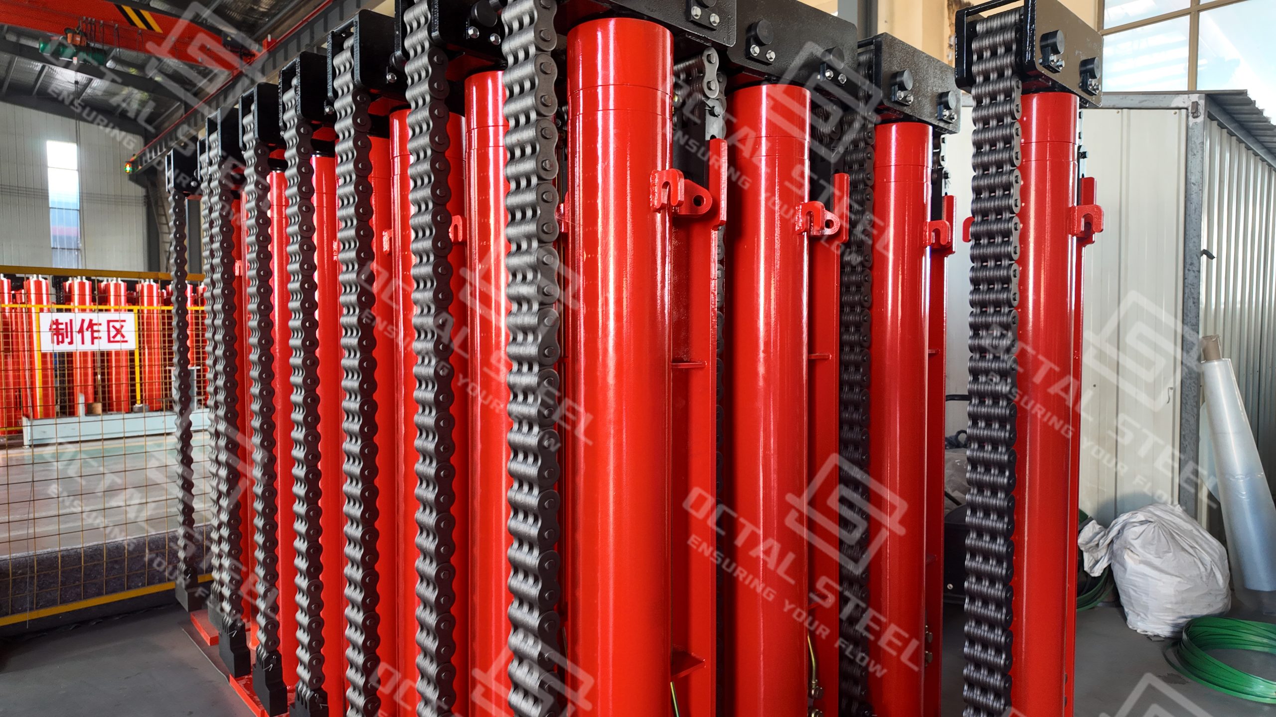
OCTAL Steel supplies two types of hydraulic tank jacking equipment: the LYT chain-type hydraulic lifting system and the SQD chuck-type hydraulic lifting system. LYT models are rated at 120, 200 and 300 kN, with a 1,500 mm active cylinder stroke and 2,700 mm chain travel. The SQD series covers six rated lifting capacities: 120, 160, 250, 350, 500 and 1,000 kN. The 120–500 kN models have a 100 mm hydraulic stroke, while the SQD-1000-200S.F has a 200 mm stroke. The two systems also differ in their mechanical lifting arrangements: LYT units transfer cylinder movement through a chain and pulley assembly, while SQD units use upper and lower chucks to grip and lift a steel rod.
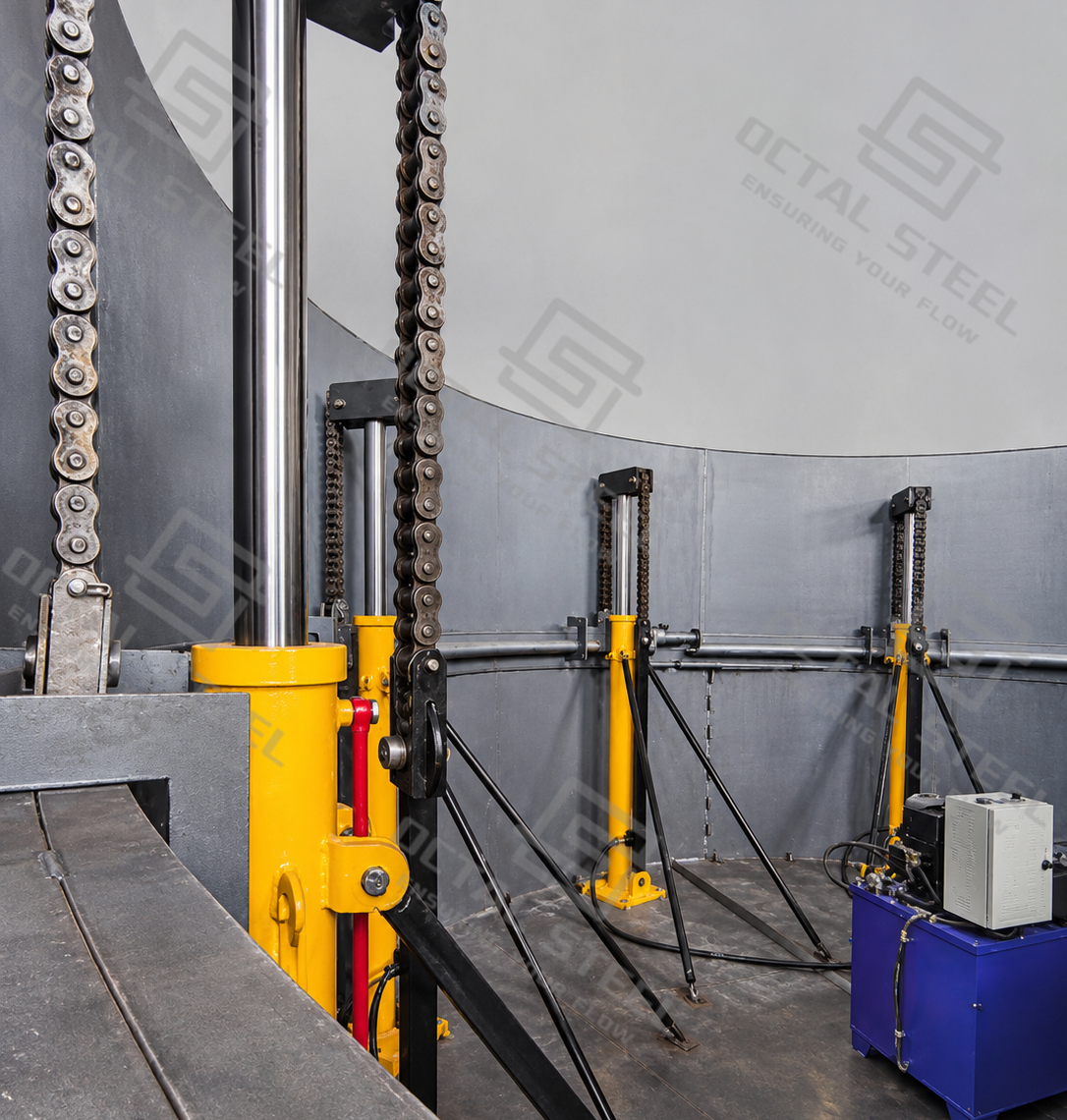
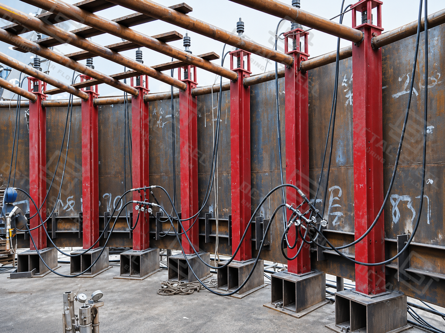
Tank Jacking System Structure, Working Principle and Technical Specifications
The LYT and SQD tank jacking systems use different mechanical arrangements to transfer and hold the lifting load. The LYT system relies on a movable pulley block and load-bearing chain, converting hydraulic cylinder travel into chain movement. The SQD system uses upper and lower chucks with a steel lifting rod, which alternately grip the rod to complete each lifting cycle. These differences determine how each system moves, supports and transfers the tank load during shell erection.
LYT Hydraulic Tank Jacking System – Chain-Type Structure
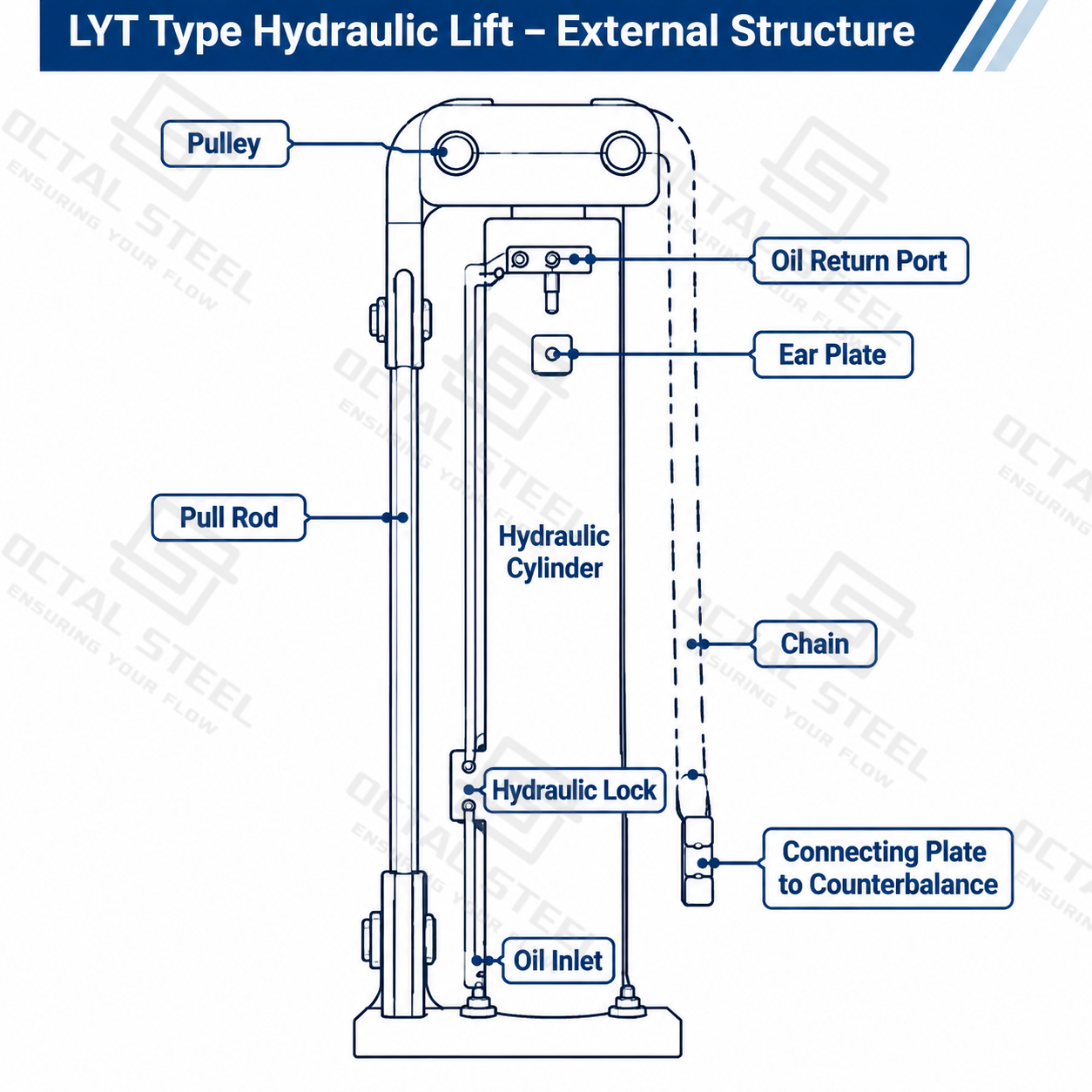
The LYT system operates through the coordinated movement of a double-acting hydraulic cylinder, movable pulley assembly and load-bearing chain. When pressurized oil enters the cylinder, the piston extends and drives the movable pulley, causing the chain to travel through the pulley arrangement. This movement transfers the lifting force to the tank’s designated lifting attachment or expansion ring, raising the assembled tank structure. Once the required lifting height is reached, the hydraulic locking arrangement helps hold the load while the next shell course is positioned and welded. The cylinder then retracts to its starting position, preparing the lifting unit for the next cycle.
Main Components and Functions
| Component | Function |
|---|---|
| Double-Acting Hydraulic Cylinder | Generates the reciprocating movement required for lifting and resetting. |
| Movable Pulley Block | Changes the direction and transmission of movement within the chain-pulley assembly. |
| Load-Bearing Chain | Transfers the lifting force to the tank’s designated lifting structure. |
| Hydraulic Lock | Helps hold the lifting load and prevents unintended movement in the hydraulic circuit. |
| Adjustable Tie Rods | Reinforce and stabilize the lifting assembly. |
| Hydraulic Oil Connections | Supply pressurized oil and provide the return circuit. |
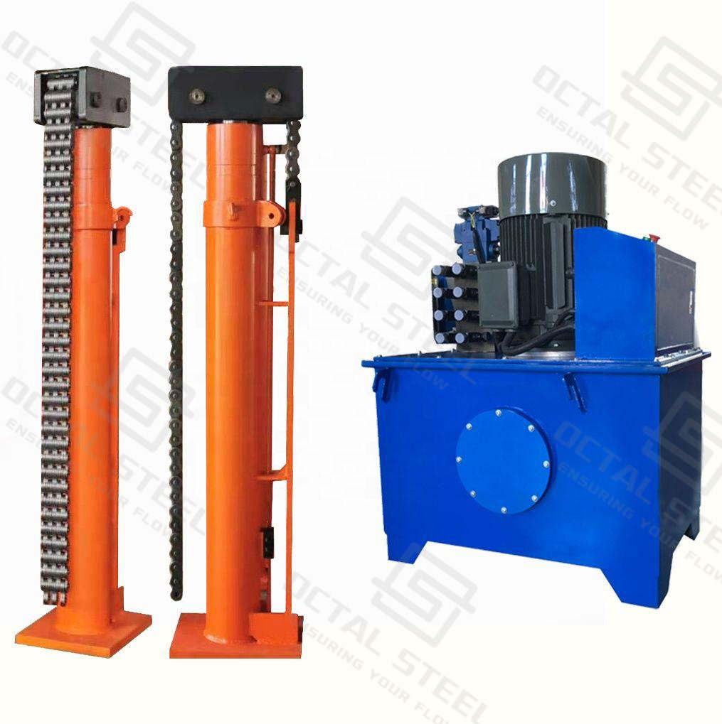
LYT Hydraulic Tank Jacking System Specifications
| Technical Parameter | LYT-120-2700 | LYT-200-2700 | LYT-300-2700 |
|---|---|---|---|
| Rated Lifting Capacity | 120 kN | 200 kN | 300 kN |
| Rated Oil Pressure | 25 MPa | 25 MPa | 25 MPa |
| Piston Stroke | 1,500 mm | 1,500 mm | 1,500 mm |
| Chain Stroke | 2,700 mm | 2,700 mm | 2,700 mm |
| Hydraulic Safety Device | Double-direction hydraulic lock | Double-direction hydraulic lock | Double-direction hydraulic lock |
| Reinforcement | 2 adjustable pull rods | 2 adjustable pull rods | 2 adjustable pull rods |
LYT Hydraulic Power Pack Specifications
| Technical Parameter | YB-7.2 | YB-14.5 |
|---|---|---|
| Hydraulic Oil Tank Capacity | 220 L | 340 L |
| Rated Pressure | 25 MPa | 25 MPa |
| Rated Oil Flow | 7.2 L/min | 14.5 L/min |
| Motor Power | 5.5 kW | 7.5 kW |
| Main Power Supply | 380 V, 3-phase, 4-wire | 380 V, 3-phase, 4-wire |
| Solenoid Valve Control Voltage | 220 V | 220 V |
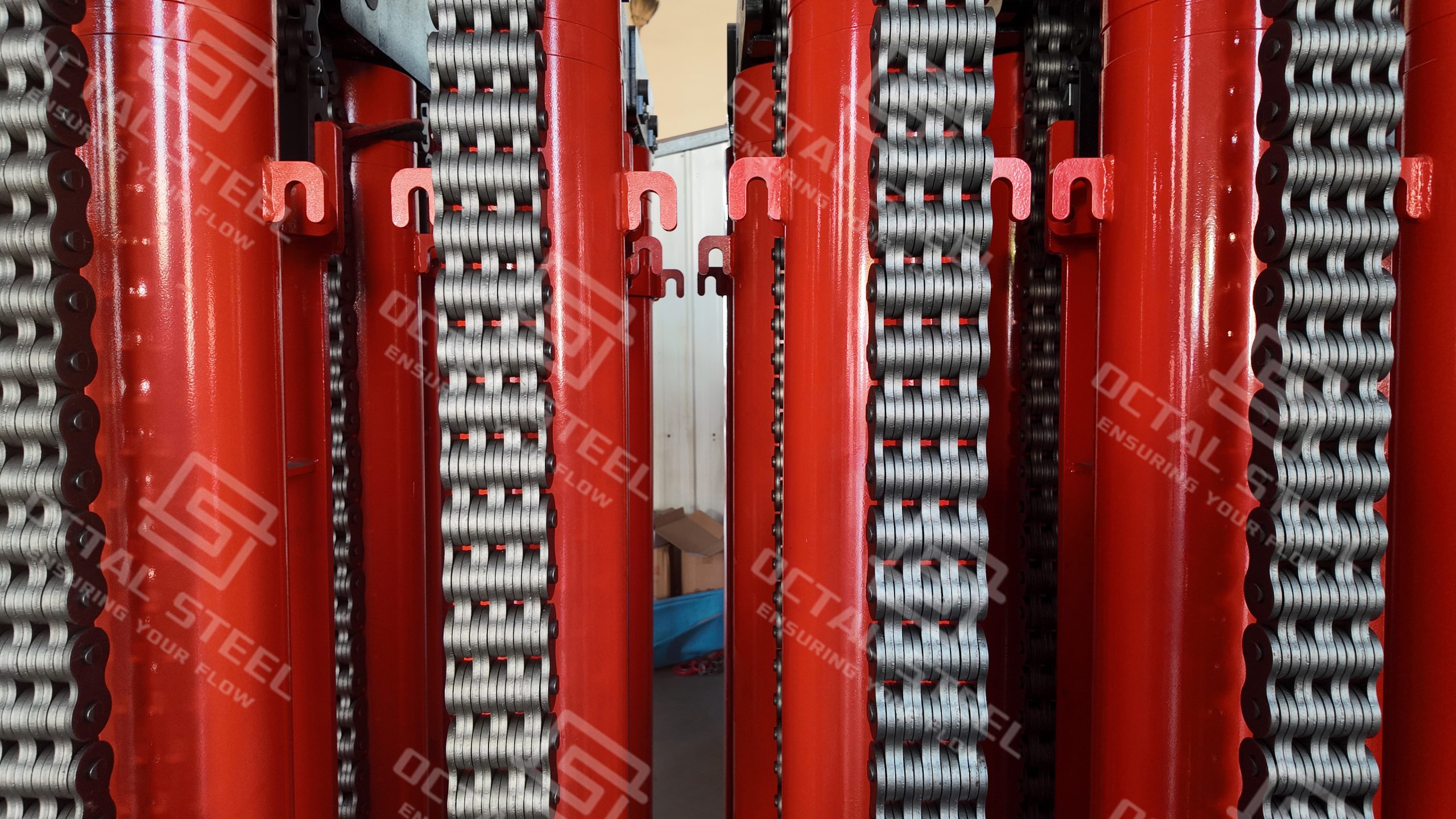
SQD Chuck-Type Hydraulic Tank Jacking System – Lifting Rod Structure
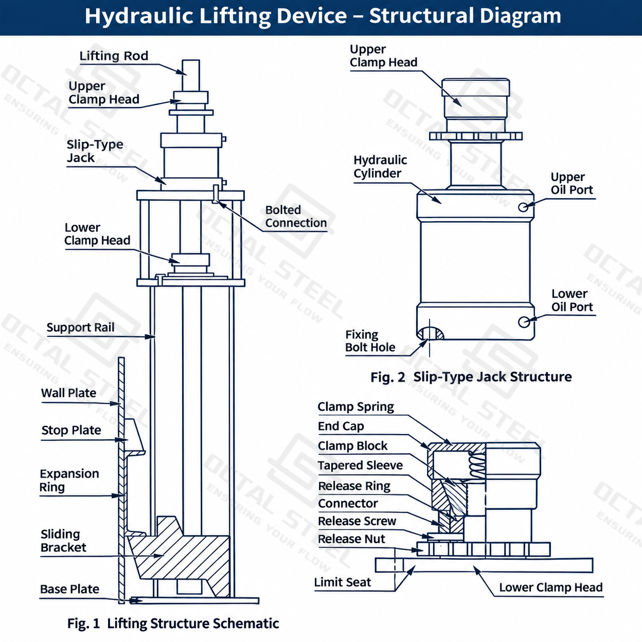
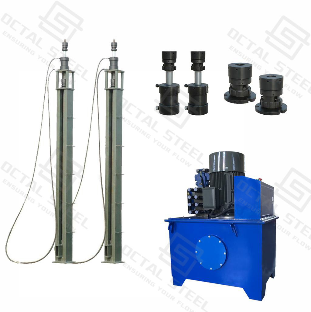
The SQD system achieves incremental lifting through the alternating engagement of its upper and lower chucks on a steel lifting rod. When pressurized oil enters the double-acting hydraulic cylinder, the upper chuck grips the lifting rod while the lower chuck releases it. The cylinder then extends, moving the lifting mechanism upward and raising the connected tank structure along the rod. At the end of the lifting stroke, the lower chuck engages the rod and holds the load while the upper chuck releases and returns to its starting position during the cylinder’s return stroke. The upper chuck then grips the rod again, allowing the next lifting cycle to begin. Through repeated gripping, lifting and resetting, the tank assembly rises progressively along the lifting rods.
Main Components and Functions
| Component | Function |
|---|---|
| Double-Acting Hydraulic Cylinder | Drives the lifting and return strokes of the jack mechanism. |
| Upper Chuck | Grips the lifting rod during the lifting stroke and moves with the lifting mechanism. |
| Lower Chuck | Holds the lifting rod and supports the load while the upper chuck resets. |
| Lifting Rod | Provides the gripping surface and mechanical load-transfer path. |
| Tank-Top Support Frame | Supports the lifting jack and connects the lifting assembly to the tank structure. |
| Slider Assembly | Guides the movement of the lifting mechanism. |
| Hydraulic Power Unit | Supplies pressurized oil to operate the lifting cylinders. |
SQD Hydraulic Tank Jack Technical Parameters
| Technical Parameter | SQD-120-100S.F | SQD-160-100S.F | SQD-250-100S.F | SQD-350-100S.F | SQD-500-100S.F | SQD-1000-200S.F |
|---|---|---|---|---|---|---|
| Rated Lifting Capacity | 120 kN | 160 kN | 250 kN | 300 kN | 500 kN | 1,000 kN |
| Rated Oil Pressure | 18 MPa | 20 MPa | 25 MPa | 20 MPa | 25 MPa | 20 MPa |
| Single Hydraulic Stroke | 100 ± 0.5 mm | 100 mm | 100 ± 1 mm | 100 mm | 100 ± 0.5 mm | 150 mm |
| Published Lifting Height | 2.6 m | 2.6 m | 2.6 m | 2.6 m | 2.6 m | 2.6 m |
| Reported Slip Value | ≤5 mm | ≤3 mm | ≤3 mm | ≤3 mm | ≤5 mm | ≤3 mm |
SQD Hydraulic Power Pack Specifications
| Technical Parameter | YB-40 | YB-60 | YT-90 |
|---|---|---|---|
| Maximum Pressure | 25 MPa | 25 MPa | 25 MPa |
| Motor Power | 11 kW | 18.5 kW | 30 kW |
| Rated Oil Flow | 40 L/min | 60 L/min | 90 L/min |
| Motor Speed | 1,470 r/min | 1,470 r/min | 1,470 r/min |
| Oil Tank Capacity | 240 L | 400 L | 400 L |
| Reference Hydraulic Oil | L-HM46 Anti-Wear Hydraulic Oil | L-HM46 Anti-Wear Hydraulic Oil | L-HM46 Anti-Wear Hydraulic Oil |
Download:Tank Jacking System Technical Specifications
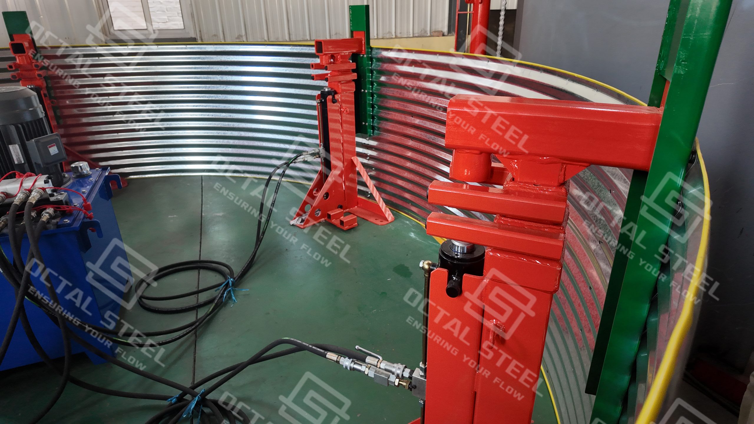
Mechanical Differences Between LYT and SQD Systems
Although both systems use hydraulic cylinders to generate lifting force, their mechanical transmission structures are fundamentally different. The LYT system relies on a pulley-and-chain assembly, whereas the SQD system uses alternating chuck engagement on a lifting rod.
| Comparison Item | LYT Chain-Type System | SQD Chuck-Type System |
|---|---|---|
| Main Load-Transfer Mechanism | Movable pulley and load-bearing chain | Upper and lower chucks with lifting rod |
| Main Lifting Member | Load-bearing chain | Steel lifting rod |
| Lifting Movement | Cylinder movement drives the pulley and chain | Cylinder strokes work with alternating chuck engagement |
| Load Holding | Hydraulic locking arrangement and chain assembly | Lower chuck grips the lifting rod during the return stroke |
| Tank Connection | Chain connected to the designated tank lifting attachment | Jack and supporting frame connected to the tank lifting arrangement |
| Main Mechanical Inspection Points | Chain, pulley, connecting pins and chain anchorage | Chuck engagement, lifting rod condition and support-frame alignment |
The two systems require separate equipment configurations. LYT chain assemblies cannot replace SQD lifting rods and chucks, and their supporting structures and operating procedures are not interchangeable. The selected arrangement must match the tank’s lifting load, lifting-point layout and installation geometry.
Hydraulic Power Pack and Oil Circuit Configuration
The hydraulic power pack and oil circuit form the hydraulic supply system of the Tank Jacking System. The pump station supplies pressurized oil to the hydraulic lifting units, while the oil circuit connects the pump station with individual lifting points. The configuration of these components determines how hydraulic power is delivered to the jacking units during tank erection.
Hydraulic Power Pack
The hydraulic pump station serves as the power source for the hydraulic cylinders used in the LYT and SQD lifting systems. It generates and supplies pressurized hydraulic oil to drive the lifting and return strokes. The pump station also incorporates the control components required for operating the hydraulic circuit.
Two reference pump station configurations, YB-7.2 and YB-14.5, are available with different oil flow rates and motor power ratings.
Hydraulic Pump Station Specifications
| Parameter | YB-7.2 | YB-14.5 |
|---|---|---|
| Oil Tank Capacity | 220 L | 340 L |
| Rated Pressure | 25 MPa | 25 MPa |
| Oil Flow | 7.2 L/min | 14.5 L/min |
| Motor Power | 5.5 kW | 7.5 kW |
| Power Supply | 380 V, three-phase, four-wire | 380 V, three-phase, four-wire |
| Solenoid Valve Control Voltage | 220 V | 220 V |
The two configurations share the same rated pressure but differ in oil flow, tank capacity and installed motor power. The applicable pump station configuration should correspond to the hydraulic requirements of the selected lifting equipment.
Hydraulic Oil Circuit Configuration
The hydraulic oil circuit connects the pump station to multiple lifting units through a main supply line, distribution pipelines and individual branch connections. During tank erection, hydraulic oil must be distributed to the lifting points according to the selected circuit arrangement. Two configurations are available: a circuit without a synchronizing valve and a circuit equipped with a synchronizing valve.
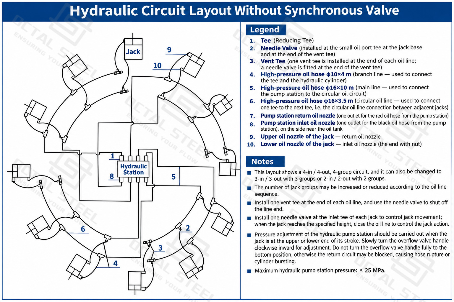
Without a Synchronizing Valve
In this arrangement, hydraulic oil is distributed from the pump station through the main pipeline, ring distribution line and branch pipelines to the individual lifting units. The branch connections are equipped with needle valves for adjusting oil flow at individual lifting points. Bleeding tees are also included in the pipeline arrangement to facilitate air release from the hydraulic circuit. Since there is no dedicated synchronizing valve to coordinate oil distribution, the operator needs to adjust the branch valves and monitor the lifting heights at different points during operation.
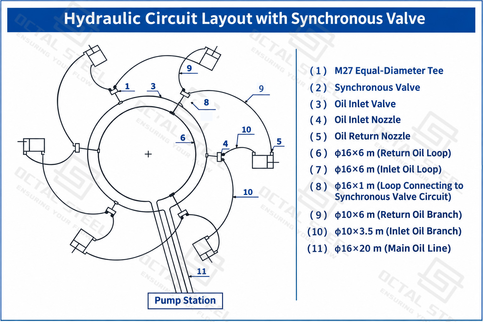
With a Synchronizing Valve
The second arrangement incorporates a synchronizing valve into the hydraulic distribution circuit. Oil from the pump station passes through the main supply connection and synchronizing valve before being distributed through the feed and return ring pipelines to the connected lifting units. The circuit also includes an M27 equal-diameter tee and individual branch connections. Compared with the arrangement without a synchronizing valve, this configuration uses a dedicated valve to coordinate hydraulic oil distribution among the lifting points, reducing the need for individual manual flow adjustment. Lifting height monitoring is still required during operation.
Download:Tank Jacking System Technical Configuration Guide
System Configuration and Tank Shell Lifting Process
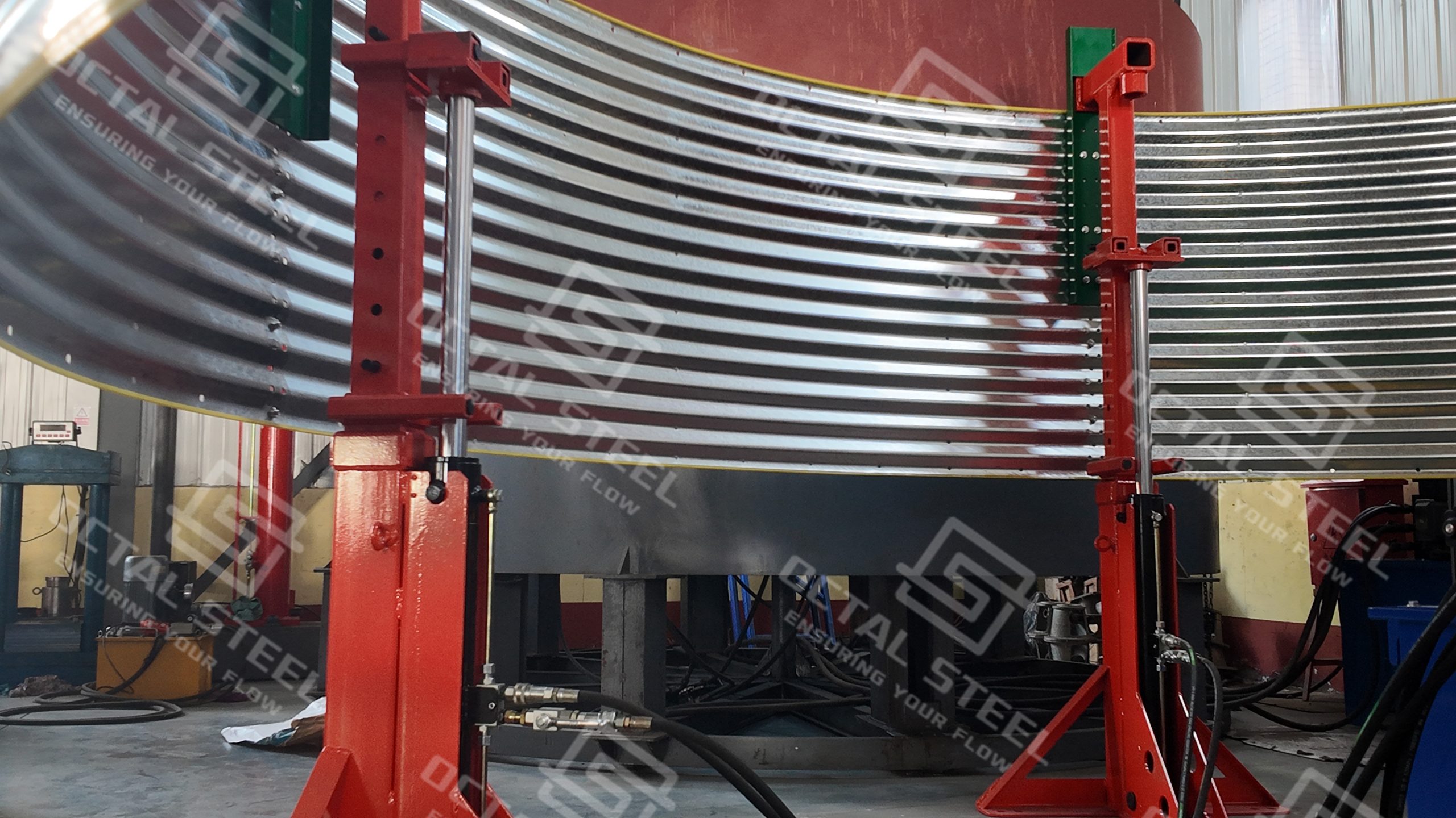
The Tank Jacking System is arranged around the tank circumference, with hydraulic lifting units connected to the designated lifting structures. The lifting units, supporting frames and hydraulic pipelines work together to raise the tank roof and assembled shell courses during inverted erection. The equipment arrangement depends on the selected LYT or SQD lifting system and the tank’s structural design.
Lifting Unit Arrangement and Installation
Hydraulic jacking units are installed at designated positions around the tank circumference. Their number and spacing are determined by the calculated lifting loads and the tank structure.
The connection between the lifting units and the tank differs between the two system types:
| System | Lifting Connection |
|---|---|
| LYT Chain-Type System | Load-bearing chains connect the lifting units to the expansion ring or designated tank lifting attachments. |
| SQD Chuck-Type System | Steel lifting rods pass through the chuck-type jacks and connect to the supporting lifting structure. |
The hydraulic supply and return pipelines are then connected between the pump station and individual lifting units. Before operation, the connections, hose routing, valve installation and hydraulic lines should be checked for correct assembly, air removal and leakage.
Tank Roof and Shell Lifting Sequence
In inverted tank erection, the tank roof and upper shell courses are assembled first at the initial working elevation. After the lifting units and their connections are installed, the hydraulic system raises the assembled structure to the required height. The next lower shell course is then positioned and welded beneath the lifted section. Once the new shell course and its supporting connections are ready to carry the load, the load is transferred to the designated support arrangement before the next lifting cycle.
The main stages are summarized below:
| Stage | Main Operation |
|---|---|
| Initial Assembly | Assemble the tank roof and upper shell courses at the initial working elevation. |
| Hydraulic Lifting | Operate the jacking units to raise the assembled tank structure. |
| Shell Installation | Position and weld the next lower shell course beneath the lifted section. |
| Load Transfer | Transfer the tank load to the designated supporting arrangement before the next lifting cycle. |
| Repeated Lifting | Repeat the lifting and shell assembly sequence until the required tank height is reached. |
Operating Monitoring and Alignment
During repeated lifting, the condition of the hydraulic system, lifting connections and tank structure must be monitored. Particular attention should be given to differences in lifting height between individual points, the condition of the load-bearing chains or lifting rods, and any deformation of the expansion ring or supporting structure.
The main monitoring items include:
| Monitoring Item | Inspection Focus |
|---|---|
| Hydraulic Pressure | Operating pressure at the pump station |
| Lifting Height | Height differences between individual lifting points |
| Lifting Components | Chain movement, lifting rod engagement and mechanical connections |
| Supporting Structure | Expansion ring deformation and support condition |
| Tank Alignment | Tank verticality and circumferential alignment |
| Hydraulic System | Oil leakage and abnormal mechanical movement |
The final lifting sequence, temporary support arrangement and welding positions must follow the approved project drawings and construction procedures.
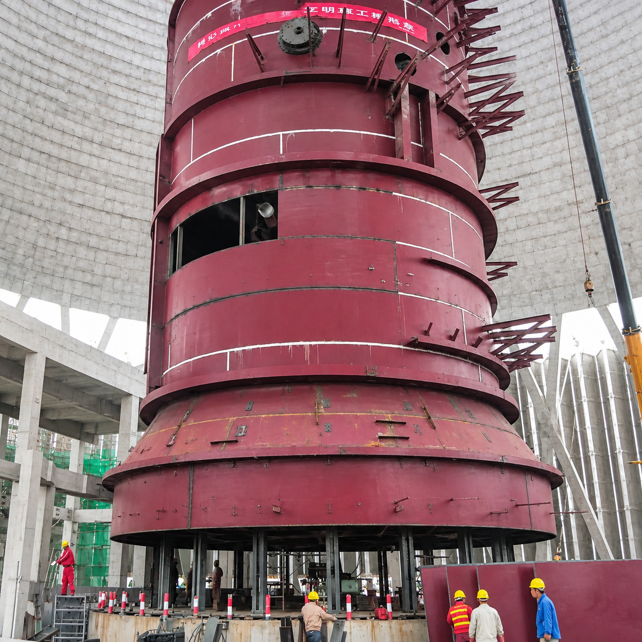
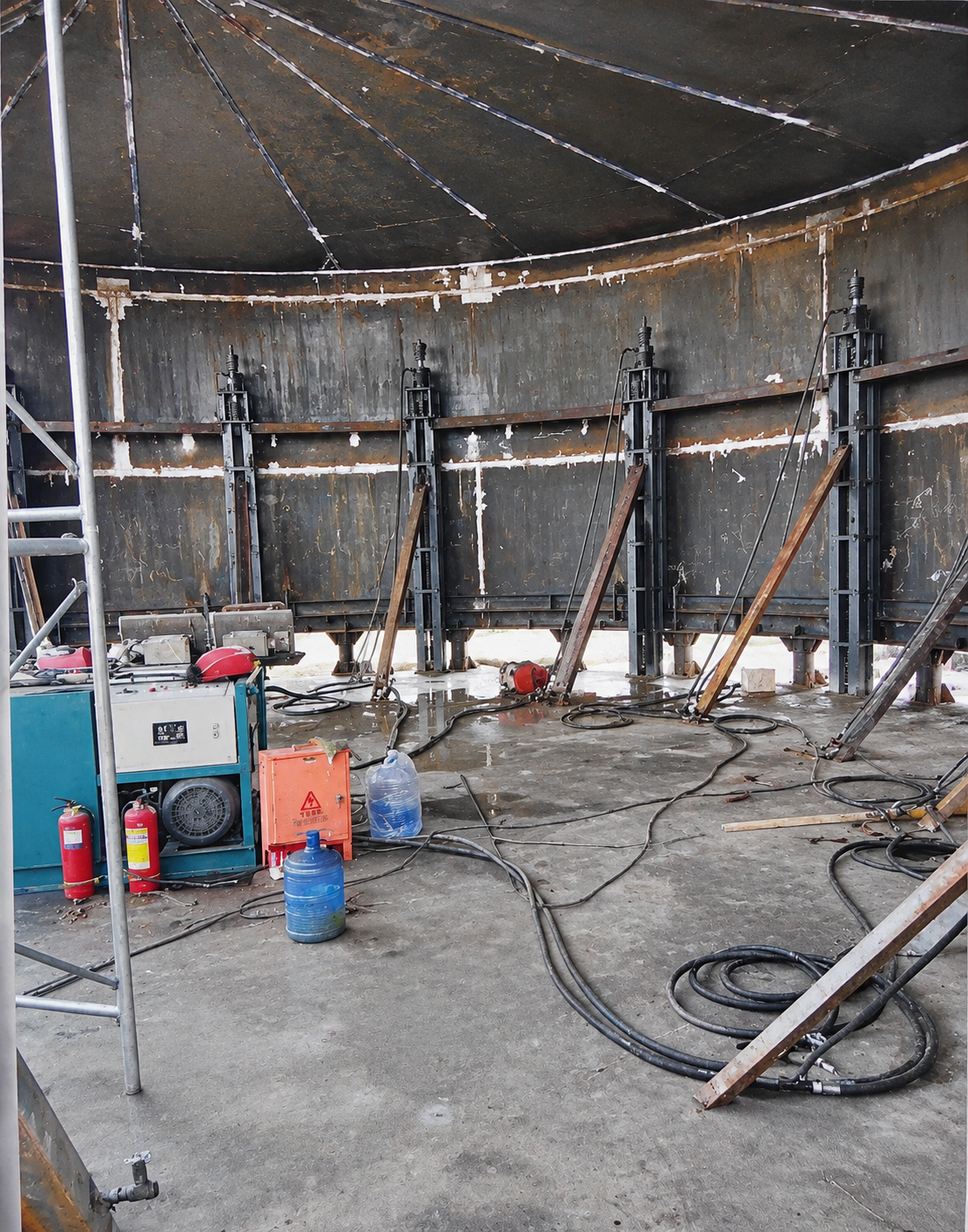
Applications of Tank Jacking Equipment
Large Vertical Steel Storage Tanks
Tank Jacking Equipment is commonly used for the inverted erection of large vertical welded steel storage tanks. During construction, the tank roof and upper shell courses are assembled first and lifted hydraulically. Each subsequent lower shell course is positioned and welded beneath the raised structure until the tank reaches its full design height.
This method is particularly applicable to large-diameter tanks where assembling the entire shell at ground level would require substantial working space and lifting capacity. The number of jacking units, lifting capacity and attachment arrangement are determined by the tank diameter, shell weight and structural design.
Vertical Steel Gas Storage Tanks and Asphalt Tanks
Large steel gas storage tanks and vertical asphalt storage tanks may also use hydraulic jacking during sectional erection. For these projects, the lifting system is connected to designated structural supports, allowing the assembled upper tank sections to be raised while additional shell sections are installed below.
The lifting arrangement must account for the weight of the assembled tank, roof structure, shell connections and any additional loads included in the lifting calculation. The suitability of inverted erection depends on the tank design and approved construction method.
Large Steel Silos and Desulfurization Towers
Hydraulic jacking can also be applied to the sectional erection of large steel silos and certain vertical steel structures used in power plant desulfurization systems. Upper sections can be assembled at a working elevation and lifted to create space for installing the next lower structural section.
For silo construction, the lifting connections must accommodate the shell structure and its supporting framework. For desulfurization towers, the lifting arrangement requires consideration of the tower section weight, structural reinforcement, lifting attachments and temporary support conditions. Both applications require project-specific structural and lifting calculations.
Hydraulic Lifting in Restricted Installation Areas
In industrial plants, some large steel structures must be assembled or lifted in areas with limited crane access, restricted overhead clearance or confined installation space. Hydraulic tank jacking equipment can be considered when conventional crane-based erection is difficult to arrange.
The SQD Chuck-Type Hydraulic Tank Jacking System, with its lifting-rod arrangement, may be suitable for projects where the installation layout favors this type of lifting mechanism. Available installation height, lifting rod length, supporting frame dimensions and clearance around each lifting point must be checked against actual site conditions.
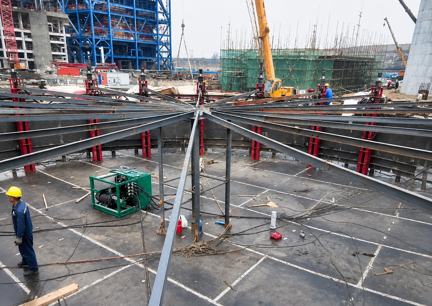
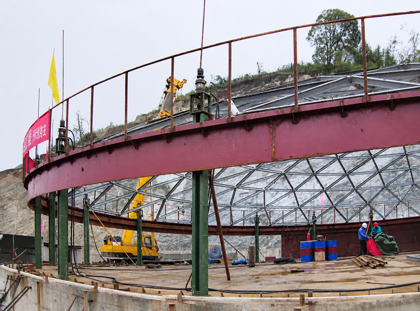
OCTAL Steel Tank Jacking System Solutions
OCTAL Steel supplies LYT Hydraulic Tank Jacking Systems and SQD Chuck-Type Hydraulic Tank Jacking Systems with equipment configurations matched to tank construction requirements. The LYT system includes hydraulic lifting units, load-bearing chains, pulley assemblies, hydraulic locks, supporting accessories, a hydraulic power pack and oil pipelines. The SQD system consists of chuck-type hydraulic lifting units, upper and lower clamping assemblies, compatible steel lifting rods, jack support frames and slider assemblies, together with the hydraulic power pack and distribution pipelines. Both configurations can be arranged with or without a dedicated synchronizing valve, depending on the selected hydraulic circuit, lifting-point layout and project requirements. The final equipment configuration is determined by the tank structure, calculated lifting load and installation conditions.
FAQ
Q:What is the difference between LYT and SQD hydraulic tank jacking systems?
A:The LYT system uses a movable pulley and load-bearing chain to transfer lifting force, while the SQD system uses alternating upper and lower chucks to grip a steel lifting rod. The selection depends on the tank lifting arrangement, load-transfer structure and installation requirements.
Q:How is the required number of tank jacking units determined?
A:The number of jacking units depends on the total lifted weight, load distribution, rated capacity of each unit and structural strength of the designated lifting points. Tank diameter, support spacing and wind loads must also be considered in the project-specific lifting calculation.
Q:What is the function of a synchronizing valve in a tank jacking system?
A:A synchronizing valve is incorporated into the hydraulic circuit to coordinate oil distribution among connected lifting units. The circuit configuration depends on the lifting-point arrangement and control requirements. Individual lifting heights still need to be monitored during operation.
Q:How do you select a compatible lifting rod for an SQD chuck-type jack?
A:The lifting rod must match the SQD jack’s chuck specifications. Its diameter, material and straightness, together with the supporting frame dimensions, must be checked against the selected model. Incorrect rod dimensions or alignment can affect chuck engagement and load transfer.
Social Share