Your Responsible Supplier Partner for Oil and Gas Products.

Skid Mounted Fuel Station
Recent Products


Rencent Articles




Skid Mounted Fuel Station
Standards: UL 142 / UL 2085 where specified, OIML R 117-1 for fuel metering, ATEX / IECEx / NEC for hazardous-area electrical equipment, NFPA 30A or local installation codes as applicable.
Fuel Types: Diesel, gasoline/petrol and other compatible refined fuels, depending on tank, seal, pump and dispenser configuration.
Capacity & Flow: Tank capacity is project-specific according to daily fuel consumption and delivery interval. Typical dispenser flow is about 40–120 L/min, with 1–4 hoses/nozzles depending on refueling demand.
Configuration: Aboveground steel storage tank integrated with unloading piping, pump, filtration, metering/dispenser, venting, overfill protection, leak monitoring, grounding/bonding and emergency shutdown system.
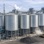
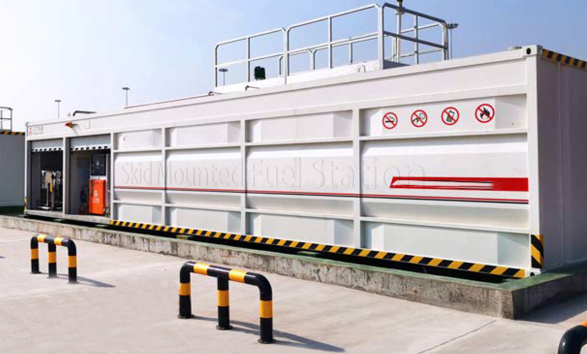
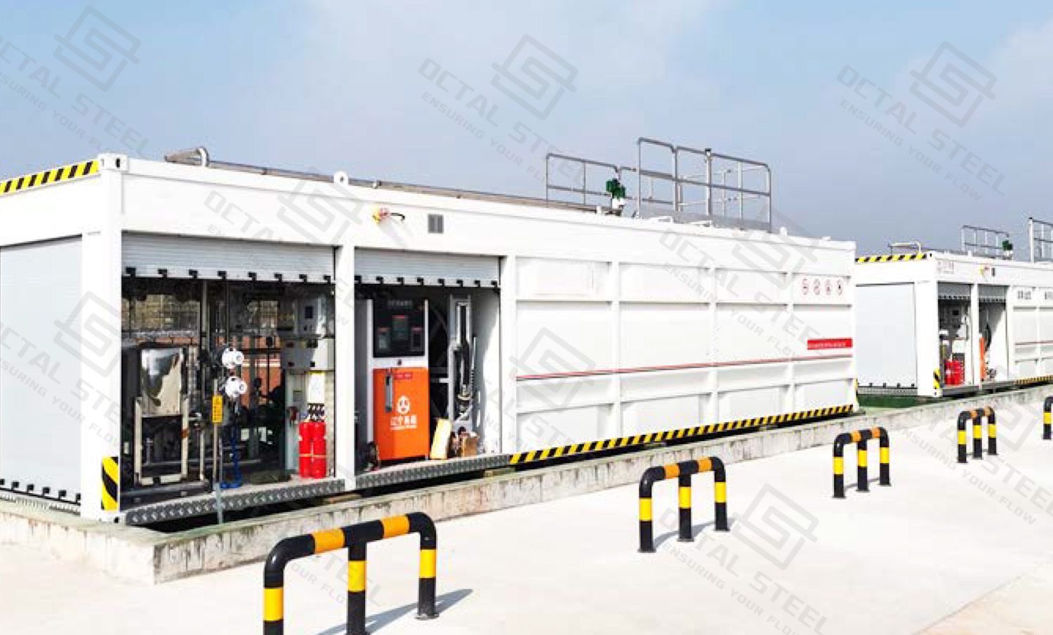
Skid Mounted Fuel Station integrates aboveground fuel storage, unloading, pumping, metering and dispensing equipment on a common structural steel base. Instead of constructing the storage tank, transfer piping and dispenser as separate site packages, the main operating interfaces can be fabricated, connected and tested before shipment, reducing field piping work and making the station easier to relocate when the project moves to a new operating area.
For oilfield, pipeline construction and remote industrial projects, station sizing should start from the actual operating profile. Daily fuel consumption, tanker delivery interval, dispenser flow, fuel type, secondary containment, hazardous-area requirements and local installation codes all affect whether the station can keep the fleet supplied without long refueling queues or insufficient fuel reserve.
Octal Steel supports project-specific skid mounted fuel station configurations for diesel, gasoline/petrol and other compatible refined fuels. Tank arrangement, dispenser capacity, unloading connections, piping, valves, instruments and documentation are defined against the actual operating duty rather than one fixed catalog configuration.
What Is a Skid Mounted Fuel Station?
A skid mounted fuel station combines fuel storage and refueling equipment on one structural steel base so that most of the piping, pumping and dispensing interfaces can be assembled before the unit reaches site. For oilfield camps, pipeline spreads, construction bases and other temporary industrial facilities, this avoids building the tank, pump and dispenser as three unrelated systems in the field.
A typical station includes:
• Fuel storage: aboveground steel tank, level indication, venting and, where specified, secondary containment or leak monitoring.
• Fuel receiving: tanker unloading connection, isolation valves, transfer piping and bonding points.
• Fuel delivery: pump, filter, meter or dispenser, hose and dispensing nozzle.
• Safety and control: emergency shutdown, high-level alarm interfaces, grounding and other project-required protection devices.
• Structural support: steel skid, equipment supports, lifting points and interfaces for installation on the prepared foundation.
The exact arrangement depends on the fuel and the way the station will be operated. A diesel station serving excavators and generators may prioritize storage volume and high dispensing flow, while a gasoline/petrol unit usually requires more attention to vapor control and hazardous-area electrical equipment.
One distinction is important: a skid mounted fuel station is relocatable equipment, not automatically a fuel transport tank. The unit is normally emptied, isolated and prepared before it is moved to another site. This is different from a tank specifically designed and approved to carry fuel on public roads.
Storage Tank Design
The storage tank normally represents the largest part of the skid, but tank volume alone does not define station performance.
Primary and Secondary Containment
Depending on the project and destination requirements, the tank may use:
• primary single-wall construction
• double-wall / secondary-containment construction
• integral containment arrangement
• single or multiple fuel compartments
For projects specifying a UL route, UL 142 covers shop-fabricated atmospheric steel tanks for stable flammable and combustible liquids. The standard includes primary, secondary-containment and diked tank configurations in horizontal or vertical arrangements. UL also distinguishes UL 2085 protected aboveground tanks, which add integral secondary containment together with enhanced fire and impact protection requirements.
A UL 142 requirement on a skid mounted fuel station applies to the storage tank itself, not automatically to the complete package. The pump, dispenser, electrical equipment and field-installed accessories are evaluated separately against the standards and approval requirements relevant to each component and project location.
Tank Openings and Venting
The nozzle arrangement normally needs to consider:
• fuel filling
• product withdrawal
• level measurement
• drain connection
• normal vent
• emergency vent
• manway or inspection access
• interstitial monitoring where secondary containment is used
For UL 142-listed tank construction, primary compartments include openings for normal and emergency venting, while secondary containment incorporates provisions for monitoring and emergency venting. Final vent configuration still has to follow the applicable installation code at the project site.
Fuel Dispenser and Metering System
The dispensing section determines how quickly the stored fuel can actually reach operating equipment.
A station serving light vehicles does not require the same flow philosophy as a station refueling haul trucks, drilling support vehicles or high-consumption construction machinery.
Fuel Dispenser Specifications and Selection Parameters
| Parameter | Typical Reference Range | Selection Note |
|---|---|---|
| Fuel Type | Diesel, gasoline/petrol, biodiesel* | Wetted parts, seals and meter must be compatible with the specified fuel |
| Dispenser Flow Rate | 40–120 L/min | 40 L/min is common for light vehicles; 70–120 L/min is more suitable for trucks and heavy equipment |
| Nozzles / Hoses | 1–4 hoses, depending on dispenser design | Number is selected from fuel grades and simultaneous refueling demand |
| Metering Performance | OIML R 117 Class 0.5, where specified | For quantities ≥ 2 L, complete-system MPE is ±0.5%; meter MPE is ±0.3% |
| Flow Range Ratio | Qmax / Qmin ≥ 10 under OIML R 117 for conventional fuel dispensers | The selected meter must remain within its approved operating flow range |
| Ambient Temperature | Typically -20°C to +45/+55°C; low-temperature options to about -40°C | Final range depends on dispenser, hose, display and electrical components |
| Power Supply | Typically 230 V, 1-phase or 400 V, 3-phase, 50 Hz | Must match the site’s available electrical supply |
| Display | Volume; optional volume + price | Price display is mainly needed for commercial fuel sales |
| Data Interface | Totalizer, RFID/FMS, 2-wire, IFSF/LON or project-specific interface | Selected according to fleet management and reporting requirements |
| Pump Arrangement | Integral suction pump or separate pressure/transfer pump | Depends on tank position, pipe length and required flow |
| Hazardous-Area Protection | ATEX / IECEx / NEC route as applicable | Certification must match the actual area classification and destination market |
* Fuel compatibility must be confirmed against the selected dispenser model.
Where fuel quantity is subject to legal metrology control, the dispenser specification may need to follow OIML R 117-1 or the applicable national metrology regulation.
OIML R 117-1:2019 contains specific requirements for fuel dispensers. Among them, where the dispenser has its own pump, a gas elimination device is required immediately upstream of the meter inlet. For an installed fuel dispenser, the ratio between maximum and minimum flow rate may be below 10 but must not be less than 5.
In practice, the dispenser should be specified by its approved flow range, metering standard, and destination-market approval, rather than by a generic claim of “high accuracy.”
Skid Mounted Fuel Station System Configuration
The station works as a complete fuel-handling chain rather than as an isolated tank.
Fuel Tanker → Unloading Connection → Storage Tank → Pump → Filter → Meter/Dispenser → Hose and Nozzle → Vehicle or Equipment
Each section controls a different operating risk.
| System Section | Main Function | Engineering Points to Confirm |
|---|---|---|
| Storage tank | Holds operating fuel inventory | Fuel compatibility, nominal capacity, single- or secondary-containment construction, compartment arrangement |
| Unloading system | Transfers fuel from tanker to tank | Connection size/type, unloading rate, isolation, bonding, overfill protection |
| Vent system | Controls tank breathing during filling and withdrawal | Normal vent, emergency vent, vapor handling where required |
| Transfer pump | Moves fuel to the dispensing system | Required flow, suction arrangement, NPSH conditions, motor/electrical classification |
| Filtration | Protects dispenser and vehicle fuel system | Filtration level, water separation where required, element access |
| Meter/dispenser | Measures and delivers fuel | Fuel type, flow range, legal metrology requirement, number of nozzles |
| Hose/nozzle | Final vehicle connection | Hose length, rated fuel service, automatic shutoff requirements |
| Instrumentation | Monitors inventory and operating status | Level indication, high-level alarm, leak monitoring, local/remote signals |
| Safety system | Stops or limits unsafe operation | E-stop, grounding/bonding, overfill alarm, electrical classification |
| Skid structure | Supports and distributes package loads | Overall dimensions, lifting arrangement, transport load, foundation interface |
This arrangement allows the final package to be configured around the actual fueling duty instead of choosing a tank capacity first and trying to fit the operating system around it later.
How to Size a Skid Mounted Fuel Station
Tank capacity should be based on actual fuel consumption and delivery logistics, rather than selected only from a commonly available nominal size. A useful starting point is:
Required operating inventory = Daily fuel consumption × Fuel delivery interval
The result represents the fuel needed between normal deliveries. Reserve inventory, usable tank volume, filling limits, delivery delays, and peak consumption should then be considered before the final tank capacity is selected.
Example: Remote Pipeline Construction Spread
A pipeline construction spread consuming 8,000 L/day with fuel deliveries every 3 days requires at least 24,000 L of operating inventory between deliveries.
| Sizing Input | Example Value |
|---|---|
| Daily fuel consumption | 8,000 L/day |
| Normal delivery interval | 3 days |
| Calculated operating inventory | 24,000 L |
Calculation: 8,000 L/day × 3 days = 24,000 L
The calculated 24,000 L is not the final tank size. Additional capacity may be required for delivery delays, reserve fuel, usable-volume limits and temporary increases in consumption.
Remote pipeline and oilfield sites often draw from one diesel supply for welding generators, excavators, sidebooms, cranes, trucks, and camp utilities. If storage is sized too close to the calculated minimum, a delayed delivery or short-term demand increase can interrupt several site activities at once.
Dispenser Flow and Refueling Time
Storage capacity determines how much fuel is available, while dispenser flow determines how long each refueling stop takes. Both need to be checked when sizing the station.
For a machine receiving 300 L of fuel:
| Dispenser Flow Rate | Theoretical Refueling Time |
|---|---|
| 40 L/min | 7.5 min |
| 80 L/min | 3.75 min |
Calculation: Refueling time = Fuel volume ÷ Dispenser flow rate
These values are theoretical. Actual refueling time can be longer because of hose pressure loss, dispenser control, vehicle tank acceptance rate, nozzle operation, and operator handling.
On sites where several trucks or machines return during the same shift change, dispenser flow and the number of available nozzles can become the limiting factor even when the station has enough fuel storage for several days.
Skid Mounted Diesel Fuel Station
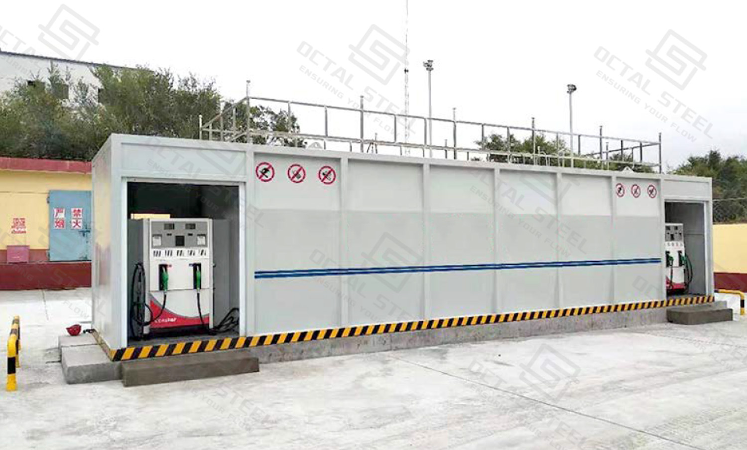
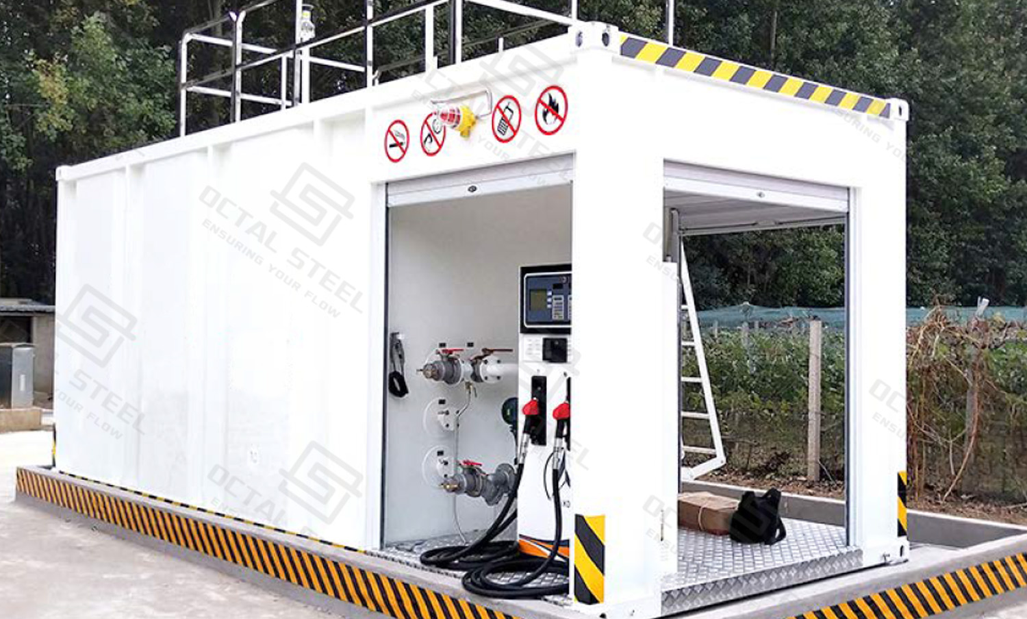
Diesel is one of the most practical duties for skid mounted fuel stations because many remote industrial operations depend on large fleets of diesel-powered equipment.
A skid mounted diesel fuel station can be configured for:
• drilling and workover support equipment
• pipeline construction machinery
• excavators and earthmoving equipment
• mobile cranes and lifting equipment
• diesel generators
• maintenance vehicles
• remote operating fleets
Even for diesel service, the station needs to be designed as a complete fuel-handling system. Tank venting, spill containment, overfill protection, electrical configuration, and transfer flow should all match the actual operating duty.
For high-turnover diesel projects, the filtration system also deserves attention. Fuel entering a remote station may pass through several transport and transfer stages before it reaches the machine. Filter arrangement and maintenance access should therefore be considered together with pump flow instead of being added after the dispenser is selected.
Gasoline and Petrol Fuel Station Configuration
Gasoline/petrol service requires a different safety review because vapor behavior and hazardous-area requirements differ from diesel service.
Depending on the destination code and station arrangement, the project may need additional consideration of:
• vapor control or vapor recovery
• classified electrical equipment
• flame and ignition-source control
• tanker unloading arrangement
• vent termination
• vehicle separation
• emergency shutdown
• fire protection
For this reason, a skid mounted petrol station should not be created by simply changing the fuel label on a diesel skid.Fuel type must be declared during the design stage so that tank accessories, seals, piping components, pumps, meters, electrical equipment and safety systems can be checked for the correct service.
Safety Protection and Emergency Control
Safety protection covers the complete fuel path from tanker unloading and tank storage to pumping and vehicle refueling. The protection required at each point is different: unloading focuses on overfill and static control, the tank requires containment and venting, while the dispensing area adds ignition control, emergency isolation and hazardous-area electrical requirements.
| Safety Risk | Protection / Control | Engineering Verification |
|---|---|---|
| Tank Overfill | Level gauge, high-level alarm and, where specified, automatic shutdown or overfill prevention | Alarm and shutdown setpoints checked against tank operating volume and tanker unloading rate |
| Fuel Leakage | Double-wall tank or other secondary containment, interstitial monitoring and controlled drain arrangement | Tank leak test, containment inspection and leak-monitoring function test |
| Spill During Transfer | Controlled unloading connection, isolation valves, drip/spill containment and defined drainage or collection area | Hose/connection inspection, valve function and site spill-control arrangement |
| Tank Overpressure / Vacuum | Normal vent and emergency vent sized for the actual filling, withdrawal and fire-exposure conditions | Vent type, size and installation checked against the applicable tank and installation code |
| Static Electricity | Dedicated bonding and grounding points for tanker unloading and fuel dispensing | Electrical continuity and grounding arrangement verified before commissioning |
| Ignition Sources | Hazardous-area equipment, no-smoking controls and separation from uncontrolled ignition sources | Area classification drawing and equipment certification checked against the installation zone |
| Emergency Condition | Accessible emergency stop to isolate pumps and dispensing equipment | Functional test confirms the intended pump, dispenser and electrical circuits shut down |
| Vehicle / Mechanical Impact | Protected dispenser and exposed piping; barriers or bollards where required by the site layout | Physical protection checked against vehicle approach and traffic route |
| Fire Response | Fire extinguishers and other project-required firefighting provisions positioned around the fueling area | Equipment type, rating, location and inspection status checked against local fire requirements |
| Unauthorized Operation | Lockable valves, dispenser access control, key/RFID system or local operating authorization where required | Access and control logic verified during FAT or commissioning |
Overfill, Leakage and Spill Containment
Tanker unloading can introduce fuel at a much higher rate than normal dispensing. Tank level indication and high-level protection therefore need to be matched to the unloading rate and available tank volume, rather than selected only from the dispenser capacity.
Where a double-wall tank or other secondary containment system is specified, the space outside the primary tank can be monitored for leakage. UL notes that listed secondary-containment tanks include provisions for interstitial monitoring, while primary tanks include normal and emergency vent openings. Final venting still has to follow the installation requirements at the project site.
For U.S. facilities that fall within EPA’s SPCC scope, aboveground oil storage exceeding 1,320 US gal in aggregate is one of the regulatory thresholds, provided the other applicability conditions are also met. Bulk-storage secondary containment is generally required to hold the capacity of the largest single container plus sufficient freeboard for precipitation. These are site-level environmental requirements rather than specifications that automatically apply to every exported skid station.
Static Control and Hazardous-Area Electrical Equipment
Fuel transfer can generate electrostatic charge, particularly during tanker unloading and dispensing. The skid should therefore provide clearly identified bonding and grounding connections at the required transfer points. OSHA requirements for flammable-liquid handling also address electrical interconnection during certain liquid-transfer operations and require precautions against ignition sources such as open flames, hot surfaces and electrical or mechanical sparks.
Electrical equipment must then be selected from the actual hazardous-area classification. Motors, junction boxes, instruments, lighting and dispenser components should only be described as “explosion-proof” when their certification matches the required ATEX, IECEx, NEC or other destination-market approval route.
Emergency Shutdown and Fire Protection
The emergency-stop system should isolate the pump and dispensing equipment specified in the shutdown logic, with the operating point positioned where personnel can reach it without approaching the immediate fuel-release area. The shutdown function should be tested as part of FAT or site commissioning rather than accepted from the presence of an E-stop button alone.
Fire protection is ultimately determined by the installation code and site layout. As one concrete U.S. construction-site example, OSHA 1926.152 requires at least one 20-B:C portable fire extinguisher within 75 ft (22.9 m) of each pump, dispenser, underground fill-pipe opening or lubrication/service area. The same OSHA section also prohibits smoking or open flames in fueling areas and requires engines to be shut down during fueling. These values should not be presented as universal requirements for every country, but they show the level of detail that needs to be checked during site design.
Manufacturing and Inspection
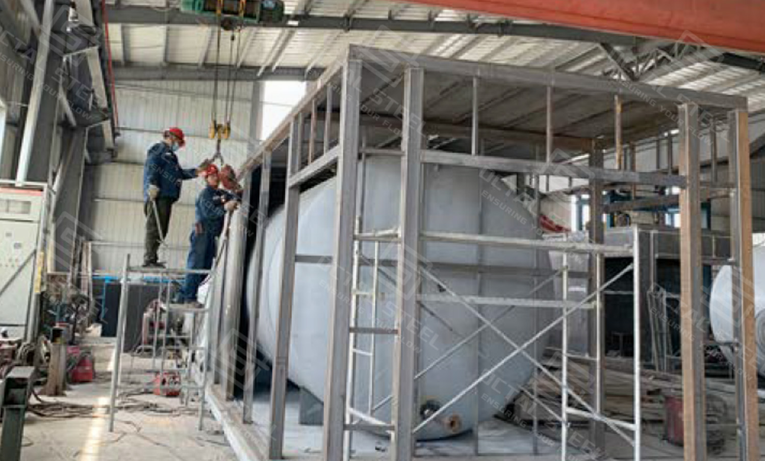
Inspection of a skid mounted fuel station covers both fabricated steelwork and the completed fuel-handling package. Tank construction, skid geometry, piping, dispenser interfaces, electrical connections and safety functions should be checked against the approved drawings and project inspection requirements before shipment.
Tank and Structural Fabrication
Material Receiving & Identification → Plate Cutting & Forming → Tank Shell & Head Assembly → Welding & Nozzle Installation → Skid Frame Fabrication
Tank-to-Skid Assembly → Piping & Equipment Installation → Surface Preparation & Coating → Leakage & Dimensional Check → Final Package Integration
The NDT method and inspection coverage should follow the applicable fabrication standard and approved ITP rather than using the same fixed percentage for every project.
Where a UL 142 listed tank is specified, the applicable leakage-testing and production requirements belong to that listed tank manufacturing route. They should not be applied automatically to tanks manufactured under another specification.
Package Integration and FAT
Once the tank, pump, piping and dispenser are assembled on the skid, inspection shifts from individual fabrication quality to the way the complete system operates.
| Package Check | What Is Verified | Why It Is Checked |
|---|---|---|
| Fuel flow path | Valve orientation, pipe routing and flow direction | Prevents reversed flow paths and incorrect valve installation |
| Pump and filtration | Pump installation, suction/discharge connections and filter accessibility | Confirms correct flow arrangement and maintenance access |
| Dispenser interface | Meter/dispenser, hose and nozzle connections | Confirms mechanical compatibility and correct fuel-delivery path |
| Tank venting and drainage | Vent, emergency vent and drain interfaces | Confirms connections match the approved tank and site arrangement |
| Instrumentation | Level indication, alarms and monitoring points | Confirms instruments are installed at the intended locations |
| Grounding / bonding | Tank, skid, dispenser and transfer grounding points | Confirms the required electrical continuity interfaces are available |
| Electrical installation | Junction boxes, cables and equipment connections | Checks wiring arrangement against the approved electrical design |
| Emergency shutdown | E-stop command and isolation of specified equipment | Confirms pumps and dispensing equipment respond to the shutdown logic |
| Drawing conformity | Complete package against P&ID and GA drawing | Confirms the delivered skid matches the approved project configuration |
A tank may pass its leakage test while the finished package still contains commissioning problems such as an incorrect valve direction, inaccessible filter, wrong vent connection or incomplete electrical interface. FAT should therefore confirm the assembled fuel path and operating interfaces before the skid is released for shipment.
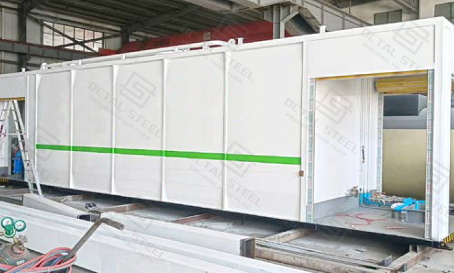
Applications of Skid Mounted Fuel Stations
Oilfield Drilling and Workover Sites
Drilling and workover locations may operate generators, cranes, forklifts, trucks and support equipment around the clock. Fuel demand changes with rig activity, so storage capacity should be based on daily consumption and delivery interval, while dispenser flow should be checked against shift-change refueling demand.
Where the operation moves between wells, a drained and isolated skid station can be relocated with the project equipment instead of installing a permanent fueling facility at each location.
Pipeline Construction Spreads
Pipeline construction regularly moves excavators, sidebooms, welding tractors, generators and transport vehicles along the right-of-way. A fixed fuel station may become too far from the active spread as construction advances.
A skid mounted station can be positioned at a controlled logistics or maintenance base closer to the work area. Tanker access, dusty conditions, simultaneous refueling and the distance to the next fuel delivery point should all be considered during sizing.
Mining and Heavy Equipment Yards
Mining and quarry operations can place high diesel demand on a station through haul trucks, loaders, excavators and generators.
Here, storage and dispensing capacity need to be balanced. A large storage tank combined with a low-flow dispenser can still create refueling queues, while high-flow dispensing with insufficient storage increases the frequency of tanker deliveries.
Remote Industrial and Project Bases
Remote compressor stations, pump stations, temporary camps and project bases may use one fuel supply for standby generators, maintenance vehicles and site equipment.
These locations often place more emphasis on reserve inventory, fuel filtration and monitoring than on public-station-style high throughput. Where fuel remains stored for longer periods, drainage, water contamination and filter maintenance also need to be considered.
How to Select the Right Skid Mounted Fuel Station
Selection should start with how the station will operate rather than with a nominal tank capacity.
| Required Input | What It Determines |
|---|---|
| Fuel type | Tank, seal, pump and dispenser compatibility |
| Daily consumption and delivery interval | Required operating inventory and tank capacity |
| Peak refueling demand | Dispenser flow rate and number of nozzles |
| Tanker unloading rate | Fill piping, venting and overfill protection |
| Fuel grades / compartments | Tank and dispenser arrangement |
| Power supply and hazardous-area requirement | Motor, dispenser and electrical equipment configuration |
| Destination country | Applicable code, metrology and certification route |
| Fuel management and documentation | RFID/FMS, reporting, inspection and handover scope |
Two stations with the same nominal tank capacity can require completely different pumps, dispensers, instruments and electrical systems. A 30,000 L station serving light vehicles is not configured the same way as a 30,000 L station refueling excavators or pipeline construction equipment.
A skid mounted fuel station also does not normally have one approval covering every component. The tank, dispenser, metering system, electrical equipment and site installation may follow different standards. The required approval route should therefore be confirmed before the equipment configuration is finalized.
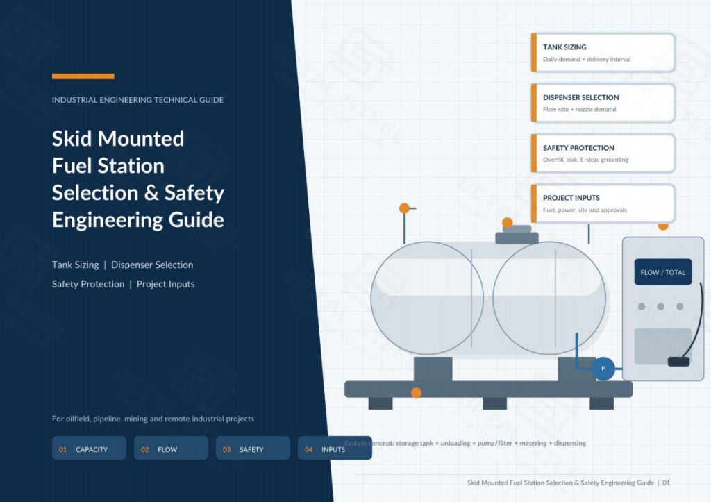
Download:Skid MountedFuel StationSelection & Safety Engineering Guide
Why Choose Octal for Skid Mounted Fuel Station Projects
Octal Steel has practical experience supporting oil and gas pipeline projects, where fuel supply equipment is often only one part of a larger field package. This means we understand how a skid mounted fuel station needs to work alongside pipeline construction equipment, temporary camps, generators, piping systems, valves and other site utilities, rather than treating it as a stand-alone tank with a dispenser.
This project background also helps us identify interface problems before shipment. Tank connections, unloading points, pump flow, dispenser capacity, piping direction, power supply and site access can be reviewed against the actual operating conditions, reducing the risk of mismatched connections or equipment that cannot meet the refueling demand once it reaches site.
Octal can also coordinate the station with the wider project supply, including steel piping, fittings, valves and related oilfield equipment, while inspection and documentation are managed around the same project requirements. Material certificates, inspection records, calibration documents and pre-shipment checks can be organized together, which is especially useful for overseas pipeline and oilfield projects where equipment acceptance depends as much on the documentation package as on the equipment itself.
FAQ
Q1: What affects the price of a skid mounted fuel station?
A: The main cost drivers are tank capacity and construction, dispenser flow and nozzle quantity, secondary containment, hazardous-area electrical equipment, fuel management functions, certification requirements, and shipping dimensions. Quotations should therefore be compared by complete technical scope, not tank volume alone.
Q2: What site preparation is required before installing a skid mounted fuel station?
A: The site normally needs a level engineered foundation, tanker and vehicle access, electrical supply, grounding, drainage or spill-control provisions, and required safety clearances. Civil and fire-code requirements should be confirmed with the local authority before installation.
Q3: What maintenance should be planned for a skid mounted fuel station?
A: Routine maintenance normally includes filter replacement, hose and nozzle inspection, pump checks, meter calibration, leak-monitoring tests, alarm/E-stop testing, tank drainage, and coating inspection. The interval should follow equipment manuals, fuel throughput and site conditions.
Q4: How is a skid mounted fuel station prepared for international shipment?
A: The station is shipped empty and secured for transport, with dimensions, weight, lifting points and center-of-gravity information confirmed before dispatch. Depending on skid size, shipment may require a standard container, flat rack or other project-specific transport arrangement.
Q5: Which approvals should be confirmed before ordering a skid mounted fuel station?
A: Approval requirements depend on the destination country, fuel type, tank design, metering use and hazardous-area classification. Tank standards, dispenser metrology, electrical certification and site installation approval should be confirmed separately before the final configuration is released.