Your Responsible Supplier Partner for Oil and Gas Products.

What Are Steel Silos Used For?
What Are Steel Silos Used For?
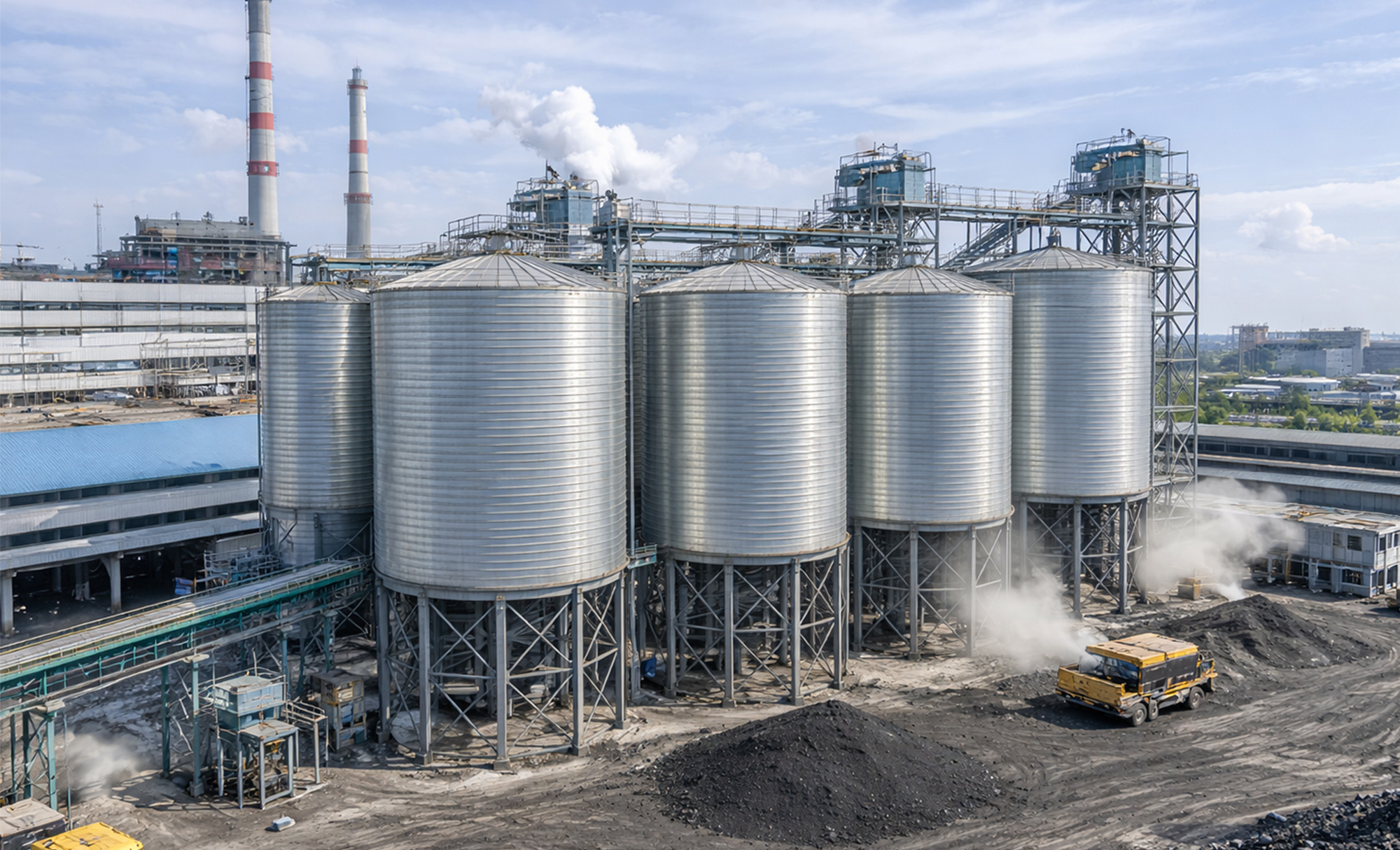
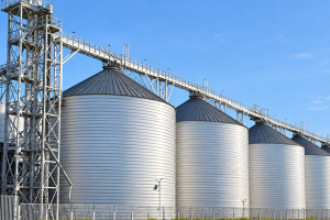
Steel silos are vertical storage structures made primarily from structural or galvanized steel, typically formed as cylindrical shells with a flat or conical bottom depending on the material and discharge arrangement. They are designed for the bulk storage of dry granular and powdered materials, with the steel shell carrying the loads generated by the stored material as well as environmental loads acting on the structure. Depending on the project, a steel silo may use bolted steel panels, welded construction, or other fabricated steel configurations.
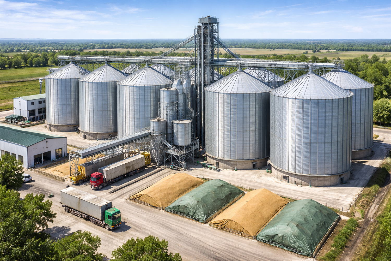
In agricultural and industrial facilities, steel silos are used to store materials such as grain, cement, fly ash, lime, mineral powders, feed pellets and other suitable bulk solids. A grain silo may hold wheat or corn between receiving and milling, while a cement or fly ash silo provides enclosed powder storage between bulk delivery and batching, processing or dispatch. In mineral and other process plants, silos are also used as intermediate storage where material needs to be accumulated before controlled feeding to the next production stage. A silo therefore performs more than a holding function: it normally operates as part of a bulk material storage and handling system, connecting material receiving with downstream production or shipment. Filling equipment, mechanical or pneumatic conveying, level monitoring, dust collection, aeration or flow assistance, and discharge equipment may all be integrated around the silo according to the stored material and operating duty.
Where Are Steel Silos Used?
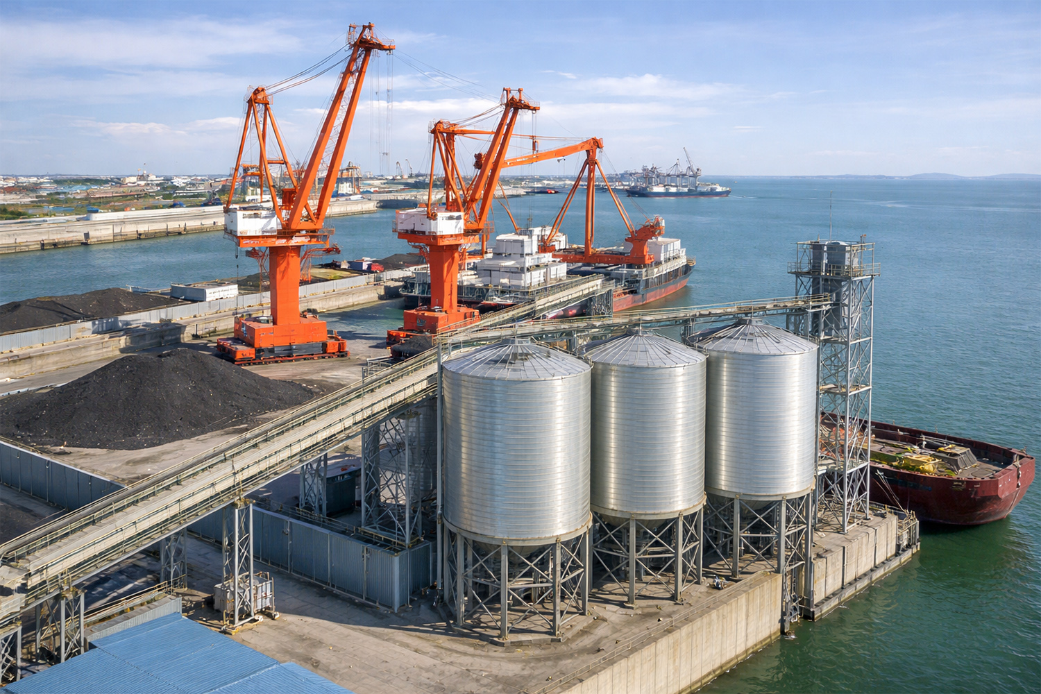
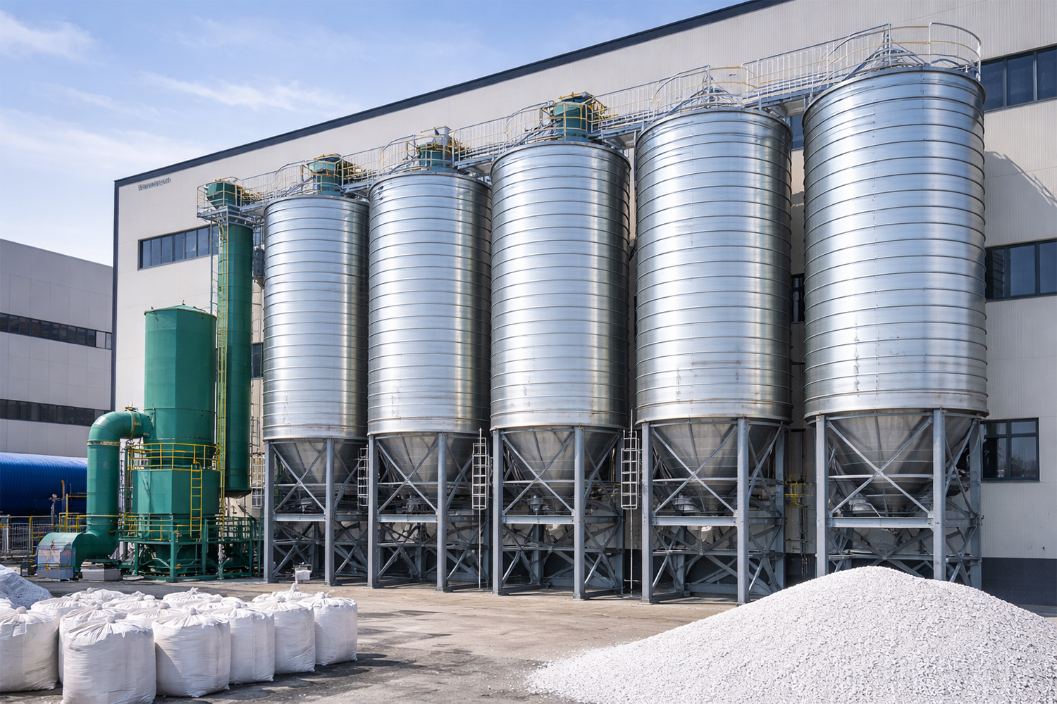
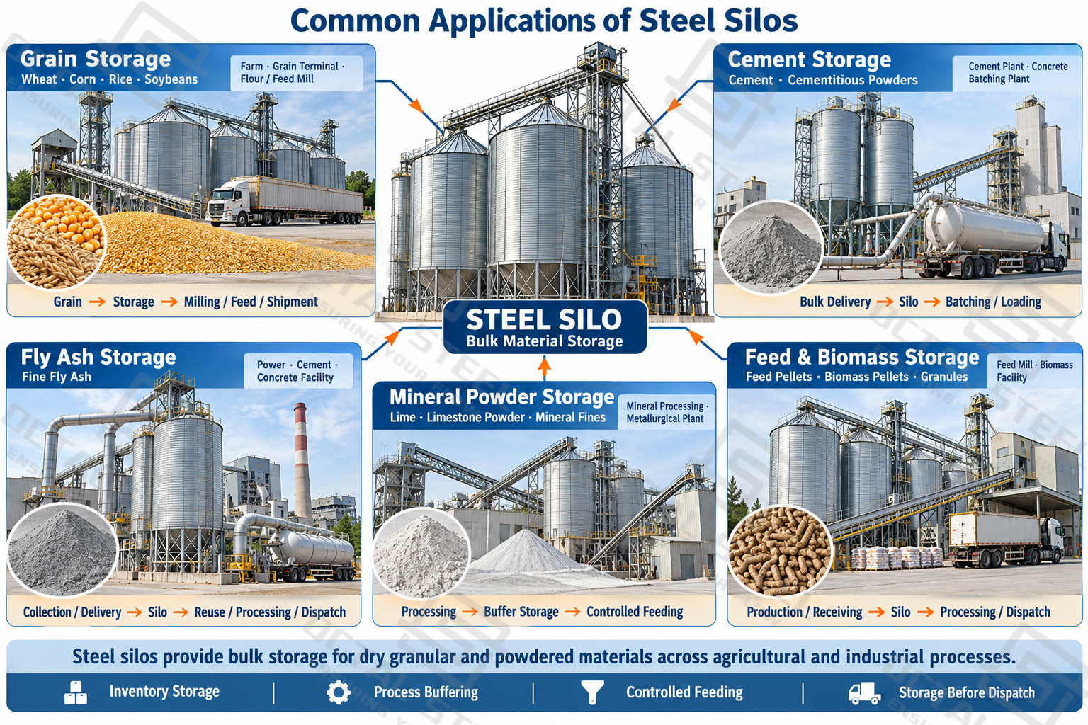
Steel silos are used wherever dry bulk materials need to be received, stored and transferred as part of an agricultural or industrial process. Their applications range from grain storage at farms and terminals to cement storage, fly ash storage and mineral powder storage in processing plants. The stored material determines not only where the silo is used, but also the main operating concerns during filling, storage and discharge.
| Application | Typical Stored Materials | Common Facility | Main Storage Considerations |
|---|---|---|---|
| Grain storage | Wheat, corn, rice, soybeans | Farms, grain terminals, flour mills, feed mills | Moisture, temperature, aeration, controlled unloading |
| Cement storage | Cement and related cementitious powders | Cement plants, grinding stations, concrete batching plants | Moisture ingress, dust control, powder flow |
| Fly ash storage | Fly ash | Power plants, cement plants, concrete plants | Dust collection, compaction, flow assistance |
| Mineral powder storage | Limestone powder, lime, slag powder, alumina and suitable mineral fines | Mineral processing, metallurgy, building-material plants | Flowability, abrasion, moisture, discharge |
| Feed and biomass storage | Feed pellets, biomass pellets | Feed mills, biomass-processing facilities | Moisture, segregation, dust, material damage |
| Industrial granular or powder storage | Suitable industrial powders and granules | Process plants | Material compatibility, contamination, flow behavior |
Download:Steel Silo Application and Material Compatibility Reference Guide
The storage duty varies considerably with the material and the process it serves. Grain may remain in a silo for extended periods before milling or shipment, while cement and fly ash are often stored as part of a continuous transfer, batching, or loading process. In mineral processing, a silo may instead provide intermediate capacity between two production stages. These different operating conditions determine how the silo is filled, how long the material remains in storage, and how it is discharged.
Grain Storage and Agricultural Processing
Steel silos are widely used for storing wheat, corn, rice, soybeans and other bulk grains at farms, grain collection centers, flour mills, feed mills and grain terminals. Depending on the facility, a steel grain silo may provide seasonal grain storage after harvest or intermediate storage between receiving and downstream processing.
In a typical grain-handling facility, material moves through receiving → cleaning or drying → silo storage → reclaim → milling, feed production or loading. The grain silo provides inventory capacity between these stages, allowing grain receiving, processing and dispatch to operate on different schedules. Large terminals may use multiple grain silos to separate grain lots and support continuous receiving and loading operations.
Storage conditions and discharge requirements depend on how long the grain will remain in the silo and where it goes next. Longer storage periods may require aeration and temperature monitoring to maintain grain condition, while the reclaim system must deliver material at a rate compatible with downstream conveying or processing equipment. These requirements can differ considerably between a farm silo and a high-throughput commercial grain terminal.
Cement Storage in Cement and Concrete Production
A cement silo is used as enclosed buffer storage between cement production or delivery and downstream consumption. In a cement plant or grinding station, silos may hold intermediate material or finished cement before further processing or bulk dispatch. In a concrete batching plant, the silo performs a different role: it maintains a working inventory of cement so that concrete production does not depend directly on the timing of bulk deliveries.
A typical batching-plant flow is bulk tanker → pneumatic filling → cement silo → discharge → screw conveyor or air slide → weighing and batching. Cement deliveries are intermittent, while the batching line draws material according to production demand. The silo separates these two operating schedules, receiving a bulk delivery when it arrives and supplying cement to the batching system as required.
Because cement is a fine powder, reliable cement storage depends on both filling and discharge conditions. Pneumatic filling introduces conveying air that must be vented while entrained cement dust is retained, and moisture ingress must be limited to reduce the risk of caking. At the outlet, consolidation or poor powder flow can restrict discharge, so the lower silo section and flow-assistance system must support the required feed rate to downstream conveying or weighing equipment.
Fly Ash Storage and Handling
A fly ash silo provides enclosed storage between ash collection or delivery and its subsequent reuse, processing or bulk transfer. It is commonly integrated with pneumatic conveying systems in power, cement and concrete-related facilities, where fly ash storage provides temporary inventory before the material is transferred to downstream production or loading equipment.
Because fly ash is a fine powder, filling and discharge require particular attention. Pneumatic filling generates dust-laden conveying air that must be properly vented and filtered, while consolidated material can make gravity discharge less reliable. Depending on the material behavior and required discharge rate, aeration or fluidization may be used to assist flow and maintain controlled transfer from the silo.
Mineral Powder, Lime and Metallurgical Material Storage
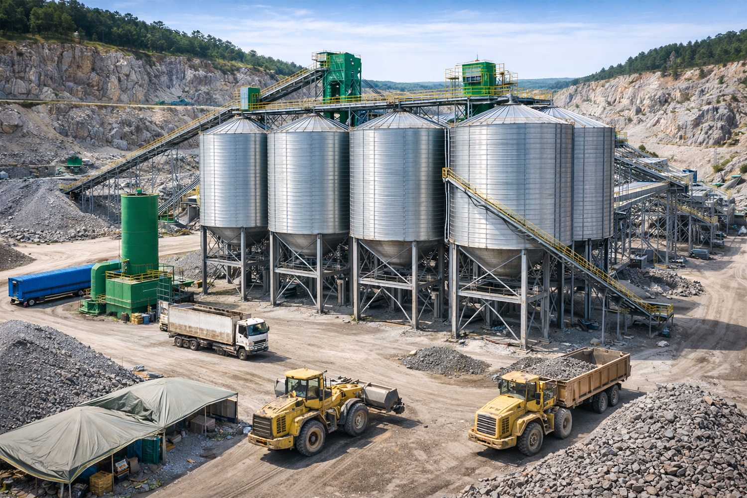
Steel silos are used for mineral powder storage and intermediate storage of selected processed mineral and metallurgical materials, including limestone powder, lime, slag powder and alumina. In these applications, the silo often serves as a process buffer between upstream material preparation and downstream feeding, rather than simply providing long-term storage.
| Stored Material | Typical Process Role | Main Handling Considerations |
|---|---|---|
| Limestone powder | Buffer storage before blending, grinding or downstream processing | Fine-powder flow, cohesion, moisture |
| Lime | Intermediate storage before dosing or process feeding | Moisture control, flowability, dust |
| Slag powder | Storage between grinding and blending or dispatch | Fine-powder flow, abrasion, controlled discharge |
| Alumina | Intermediate storage and controlled process feeding | Particle handling, dust, abrasion and contamination control |
| Processed mineral fines | Buffer storage between processing stages | Particle size, cohesion, abrasion and outlet flow |
A typical process arrangement is upstream processing → conveying → silo or buffer storage → controlled feeding → downstream process. The silo absorbs short-term differences between the output of upstream equipment and the material demand of the next production stage, helping maintain a more stable feed to downstream equipment. Where the stored material is abrasive or difficult to flow, particular attention is required at inlet impact zones, hopper transitions and discharge points, where repeated impact, sliding wear or restricted flow can directly affect operation.
Feed, Biomass and Other Granular Materials
Steel silos are also used for granular material storage in feed mills, biomass-processing facilities and other industrial plants. Typical materials include feed pellets, biomass pellets and suitable industrial granules. Storage requirements vary with the product: pellets may be susceptible to breakage or segregation during handling, while moisture, dust and contamination can be important for other granular materials. Filling and discharge arrangements should therefore be matched to the material and the requirements of the downstream process.
What Functions Does a Steel Silo Perform Beyond Storage?
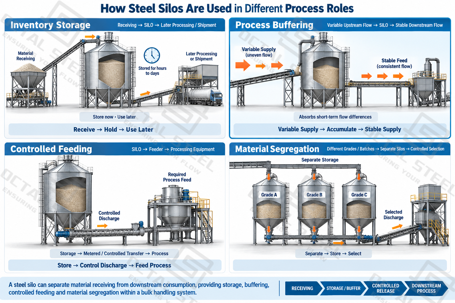
A steel silo is often positioned between material receiving and the next stage of production or dispatch. Its role depends on how material moves through the facility: some silos hold inventory for an extended period, while others receive and discharge material repeatedly as part of an operating process. In both cases, the silo provides a defined point where bulk material can be accumulated, separated and released according to downstream demand.
| Function | Role in Operation |
|---|---|
| Inventory storage | Holds bulk material between receiving and later processing, loading or shipment |
| Process buffering | Absorbs short-term differences between upstream material supply and downstream consumption |
| Controlled feeding | Maintains an available supply for delivery to downstream equipment at the required operating rate |
| Material segregation | Keeps different grades, batches or material types separate where the process requires segregation |
| Production continuity | Provides temporary inventory when material receiving and downstream production operate on different schedules |
In process applications, the silo provides a buffer between upstream material supply and downstream consumption. This allows connected equipment to operate at different instantaneous rates while maintaining a more stable material supply to the next stage.
The required silo capacity therefore depends on more than the maximum quantity of material to be stored. Material turnover, operating schedule and the required process buffer also influence the capacity needed. Some silos are intended for longer-term inventory storage, while others may hold material only long enough to maintain continuity between connected processes.
Common Steel Silo Configurations
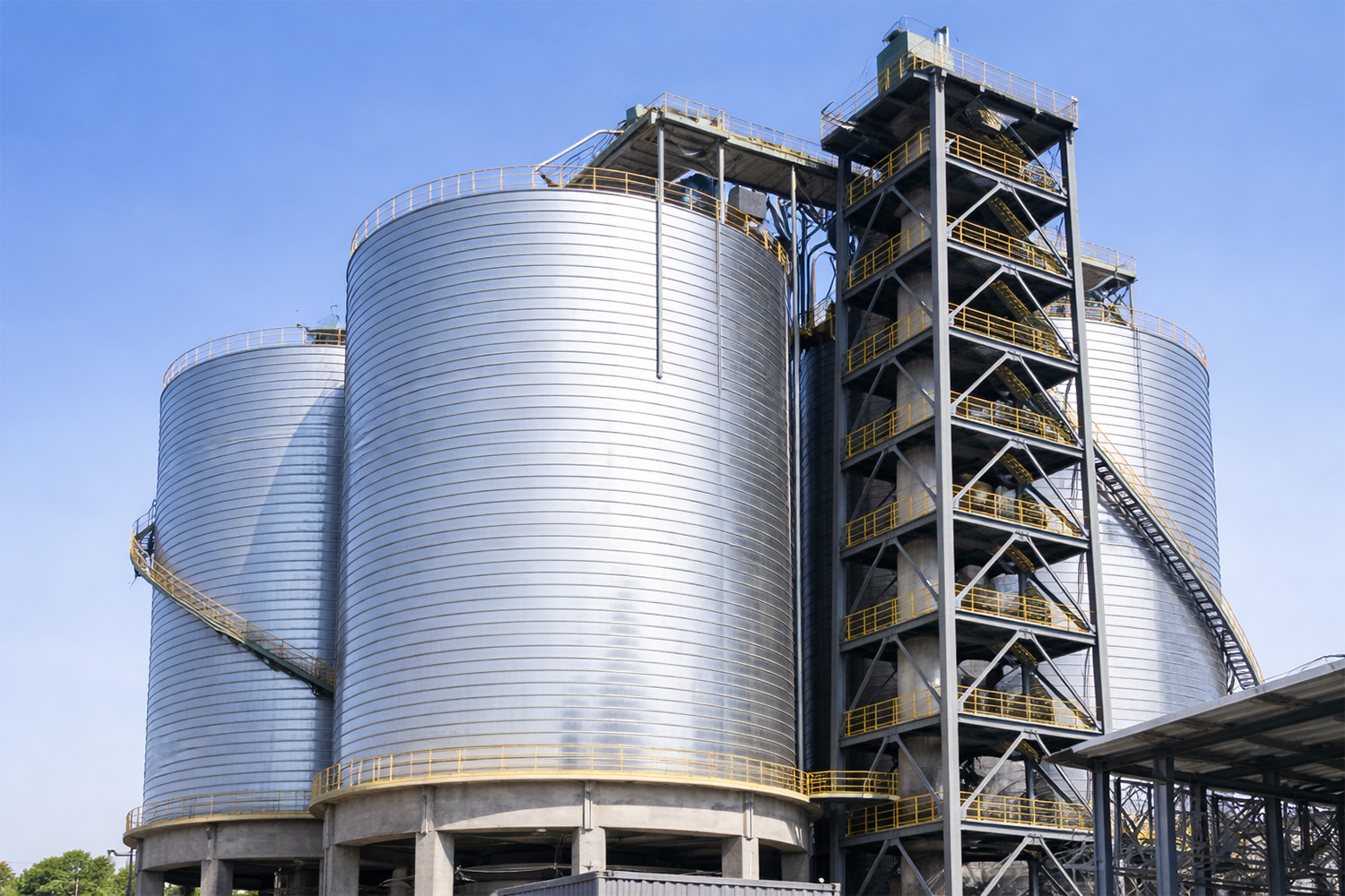
Steel silo configuration is determined by both the shell construction and the bottom arrangement. The shell may be assembled from prefabricated bolted panels, fabricated as a welded structure, or formed on site using a spiral-forming process. Independently of the shell construction, the lower section may use a flat floor or a hopper arrangement according to storage capacity, material flow behavior and the required discharge method.
Steel Silo Construction Methods
The construction method defines how the silo shell is fabricated, joined and erected, and has a direct influence on transportation, site assembly and construction quality control.
| Construction Method | Shell Construction | Project Considerations |
|---|---|---|
| Bolted steel silo | Prefabricated steel panels are joined by bolted connections during site erection | Panelized construction facilitates transport and site assembly; joint sealing and connection quality are important during erection |
| Welded steel silo | Steel plates or prefabricated shell sections are welded to form a continuous shell | Requires controlled welding, dimensional accuracy and inspection during fabrication and erection |
| Spiral-formed steel silo | Steel strip is continuously formed and joined on site to build the cylindrical shell | Requires dedicated forming equipment and an erection sequence suited to continuous on-site shell construction |
These construction methods mainly change how the shell is manufactured and erected, rather than defining what material the silo can store. A bolted system shifts more fabrication work to prefabricated panels and site connections, while a welded silo relies more heavily on welding and dimensional control during fabrication and erection. Spiral forming follows a continuous on-site construction process and therefore has different equipment and site requirements. The appropriate method depends on the required silo geometry, fabrication route, transport limitations and erection conditions.
Flat-Bottom and Hopper-Bottom Silos
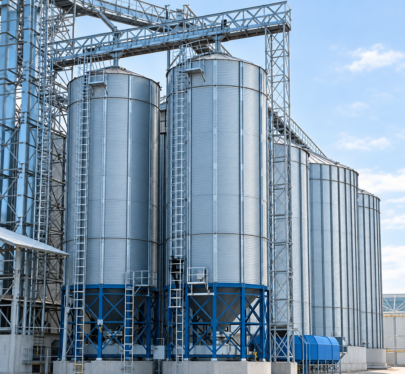
Steel silos commonly use a flat-bottom or hopper-bottom configuration. The main difference is how the lower section supports the stored material and directs it toward the discharge outlet. This affects usable storage volume, gravity discharge and the type of reclaim equipment required.
| Configuration | Bottom Structure | Material Discharge | Typical Operating Characteristics |
|---|---|---|---|
| Flat-bottom silo | Flat or nearly flat floor beneath the stored material | Material near the outlet discharges by gravity; remaining material may require mechanical reclaim | Suitable for large-volume storage where maximizing storage capacity is important |
| Hopper-bottom silo | Sloped hopper directs material toward one or more outlets | Material moves toward the outlet mainly by gravity | Better suited to frequent discharge and applications where lower residual inventory is preferred |
The bottom configuration should be selected according to storage capacity, discharge frequency and material flow behavior. A hopper bottom can improve gravity discharge, but it does not by itself solve flow problems in cohesive powders. Flat-bottom silos, meanwhile, require the reclaim arrangement to be considered together with the floor and outlet layout.
How Are Steel Silos Filled and Discharged?
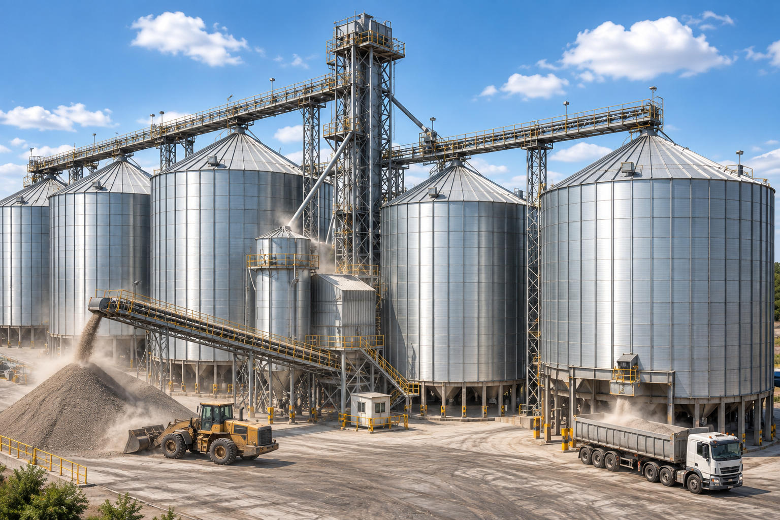
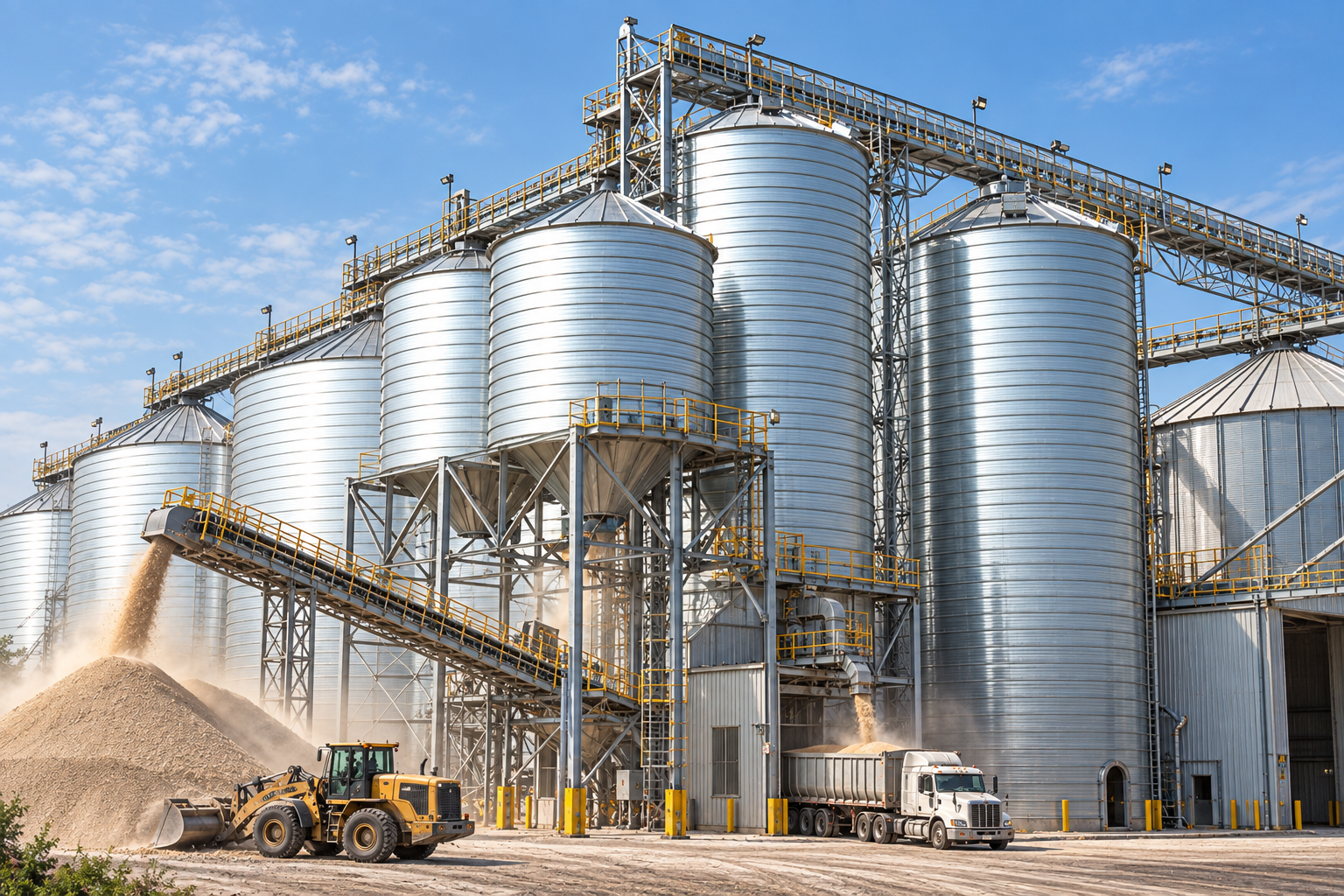
The filling and discharge arrangement of a steel silo depends on the physical form and flow behavior of the stored material, as well as the transfer rate required by the process. Granular materials are commonly handled by mechanical conveying equipment, while fine powders may be transferred pneumatically. At the outlet, the discharge system must move material from storage to the next conveyor, feeder, weighing system or processing stage at a controlled rate.
| Material / Application | Typical Filling Method | Typical Discharge Method |
|---|---|---|
| Grain | Bucket elevator with belt, chain or other mechanical conveying equipment | Gravity discharge to conveyor; flat-bottom storage may require additional reclaim equipment |
| Cement | Pneumatic conveying from bulk tanker or process conveying system | Gravity or assisted discharge to screw conveyor, air slide, weighing or loading equipment |
| Fly ash | Pneumatic conveying from collection, transport or processing systems | Controlled discharge with aeration or fluidization where required |
| Mineral powders | Mechanical or pneumatic conveying depending on particle characteristics and plant layout | Gravity discharge, feeder or flow-assistance system according to material behavior |
| Feed and biomass | Mechanical conveying using elevators or conveyors | Gravity discharge to conveyor, feeder or downstream processing equipment |
Pneumatic filling introduces conveying air into the silo together with the material. This air must be released while entrained dust is retained, so venting and dust filtration form part of the filling system. At the discharge end, the selected arrangement must provide stable material flow under the actual storage conditions, particularly where the material is prone to consolidation or poor flow.
The discharge system must also match the required downstream feed rate. A silo may provide sufficient storage capacity but still restrict production if the outlet or conveying equipment cannot deliver material at the required rate. Filling rate, storage volume and discharge capacity should therefore be considered separately when specifying the silo system.
How Does the Stored Material Affect Silo Configuration?
The design of a steel silo is closely related to the physical and handling properties of the stored material. Bulk density influences storage volume and structural loading, while particle size, cohesion and wall friction affect how the material moves through the silo and discharges at the outlet. Moisture, abrasiveness, dust characteristics and material temperature introduce further requirements for storage condition, wear control and auxiliary equipment. These properties should be defined from representative material data and actual operating conditions before the silo configuration and discharge system are finalized.
| Material Property | Effect on Silo Design | Practical Engineering Concern |
|---|---|---|
| Bulk density | Determines storage volume for a given mass and contributes to structural loading | Use representative values for the actual material condition |
| Flow properties | Cohesion, particle size and wall friction influence hopper flow and discharge behavior | Poor-flowing materials may require suitable outlet geometry or flow assistance |
| Moisture sensitivity | Can affect caking, adhesion, corrosion and stored-product condition | Storage protection should reflect the material and expected storage period |
| Abrasiveness | Influences wear at inlet, transition and discharge areas | High-wear zones may require appropriate wear protection |
| Dust and material condition | Affect filling, venting, filtration and material management during storage | Requirements depend on the material, filling method and operating conditions |
The same silo capacity can lead to very different design requirements when the stored material changes. A denser material increases the stored mass and resulting structural loads for a given volume, while a cohesive powder may require greater attention to outlet geometry and flow assistance to achieve reliable discharge. Abrasive products place additional wear demands on inlet and discharge areas, whereas moisture-sensitive materials require tighter control of water ingress and storage conditions. For this reason, changing the stored material should be treated as a change in design basis, not simply as a change in silo contents.
FAQ
Q: Can a steel silo store any bulk material?
A:No. Steel silos can store many dry powders and granular materials, but suitability depends on bulk density, flowability, moisture sensitivity, abrasiveness and other material characteristics. Cohesive, corrosive or difficult-flowing materials may require a different silo configuration, lining, discharge system or other project-specific measures.
Q: Why can’t the same steel silo design be used for different materials?
A:Different materials generate different storage and handling conditions. Bulk density affects stored mass and structural loading, while flow behavior influences hopper geometry and discharge. Moisture sensitivity, dust and abrasiveness can also change the requirements for filling, venting, wear protection and material handling. A change in stored material may therefore require changes to the silo design basis.
Q: Are steel silos only used for long-term storage?
A:No. A steel silo may provide long-term inventory storage, short-term process buffering or frequent turnover storage. In a production line, it can accumulate material between two process stages and provide a more stable supply when upstream delivery and downstream consumption do not occur at the same rate.
Q:Does a larger steel silo always provide better storage performance?
A:No. Storage volume is only one part of silo performance. The filling rate, material flow behavior, discharge capacity and downstream equipment must also match the operating requirement. A silo can hold sufficient material but still restrict production if material cannot be discharged at the required rate.



Tags:steel platesteel plate manufacturersteel silo
Related Products
Related Resources


Recent Faqs
Rencent Articles

Hot Topic

Custom Posts

Octal is located in China recognized as a leading supplier, distributor, and manufacturer union in providing piping solutions for oil and gas company. Product ranges in Steel Pipe, Casing and Tubing, Steel Plate, Sucker Rod, Steel Pipe Fittings, Valves, and Equipment for pipelines.
Contact Info
Unit 2544, 25/F, Tower A, Wanda Plaza, Wenfeng District, Anyang, Henan, China & Building A, No.18 Dirun Road, Zhengdong New District, Zhengzhou, Henan, China
+86 372 2157660 / +86 186 3727 1277
[email protected]