Your Responsible Supplier Partner for Oil and Gas Products.

Cryogenic Liquid Tank
Recent Products

Rencent Articles


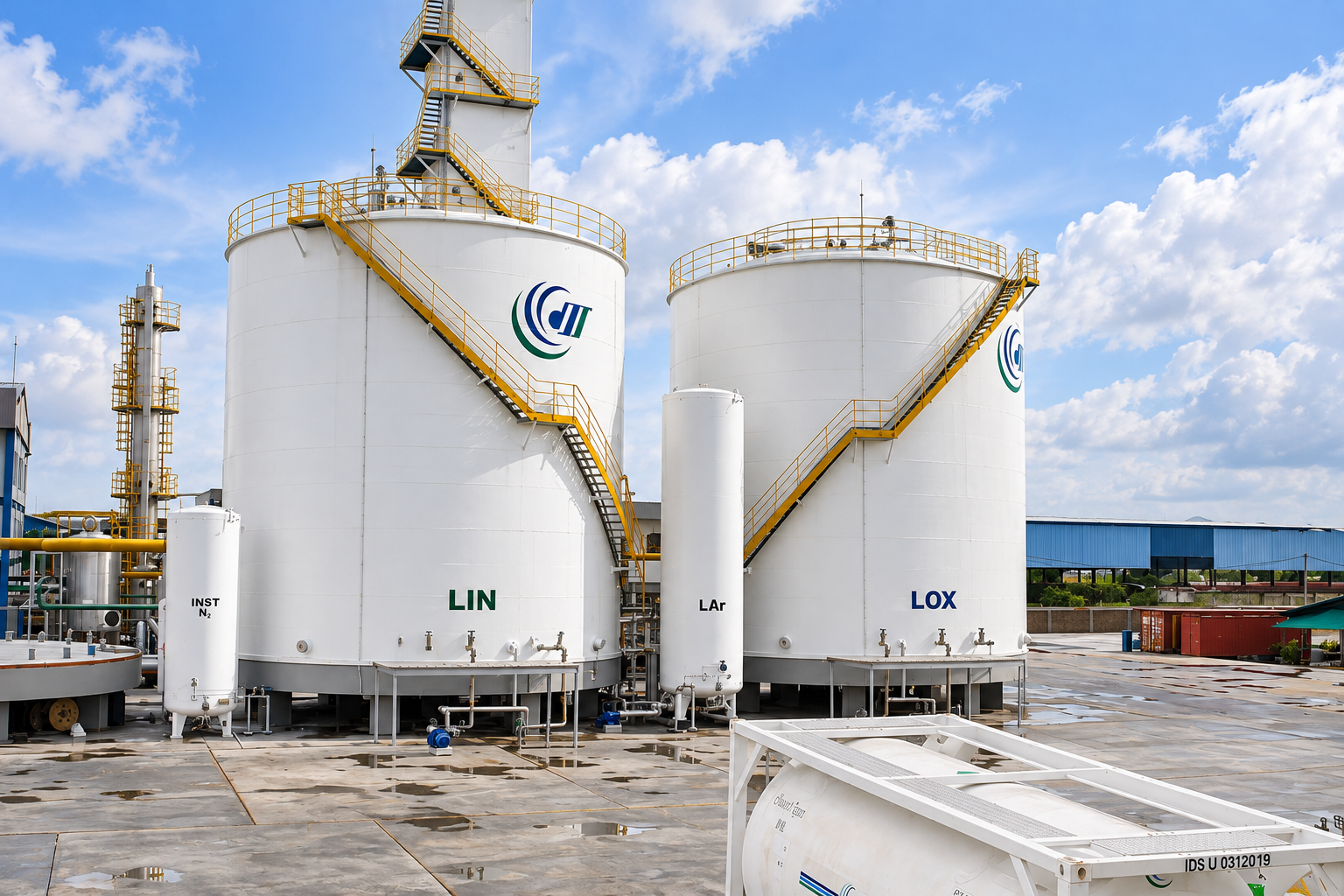
Cryogenic Liquid Tank
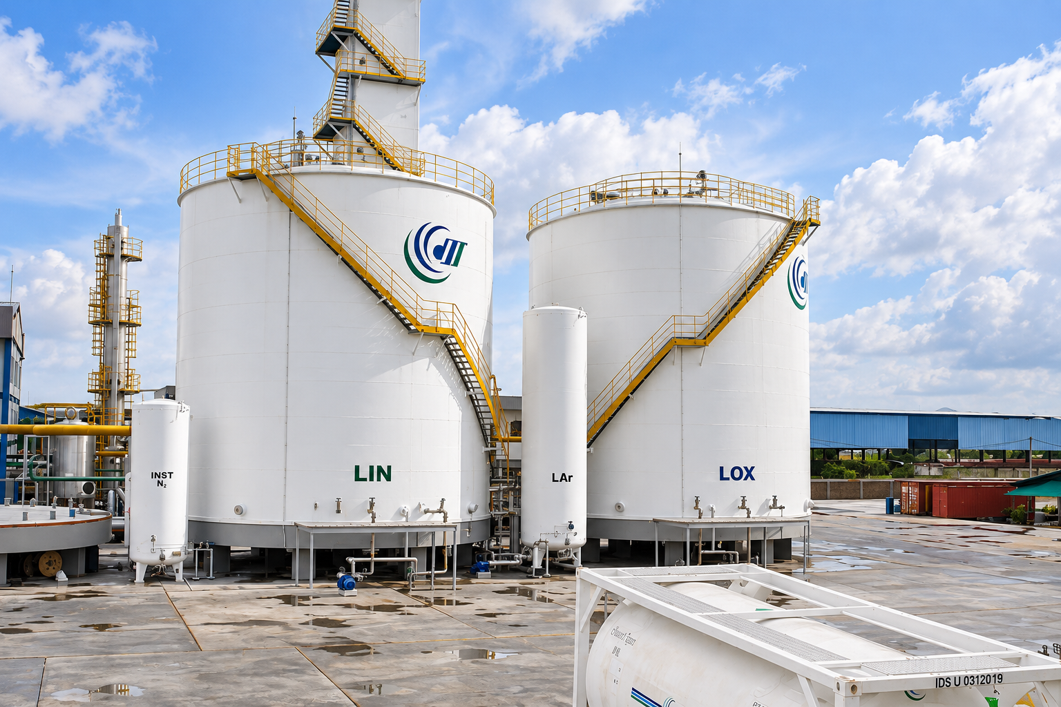
Tank Type: Vertical, flat-bottom, double-wall insulated storage tank
Storage Media: Liquid oxygen (LOX), liquid nitrogen (LIN), liquid argon (LAr)
Reference Capacities: 900, 1,200, 1,500, 3,000 and 6,000 m³
Materials: Cryogenic stainless steel inner tank, carbon or low-temperature steel outer shell
Design Standards: API 620, API 625, EN 14620
Construction: Factory prefabrication and field erection
Cryogenic liquid tanks are specially engineered storage vessels designed to hold liquefied industrial gases at extremely low temperatures while controlling heat ingress, vapor generation, and internal pressure. Large-capacity cryogenic liquid storage tanks generally use a vertical, flat-bottom cylindrical structure with an inner liquid-containing vessel, an outer enclosure, and an insulated space between them. This arrangement enables the bulk storage of liquid oxygen (LOX), liquid nitrogen (LIN), liquid argon (LAr), and other refrigerated liquefied gases at temperatures that may approach −196°C, depending on the stored medium.
Octal Steel’s cryogenic liquid tank solutions are intended for industrial gas production facilities, air separation units, steel plants, and chemical processing projects requiring substantial onsite liquid storage. Tank configurations include double-wall structures with suspended or domed roof arrangements and project-specific containment designs. The selection of tank capacity, operating pressure, cryogenic materials, insulation, and safety systems follows the stored liquid’s physical properties, relevant design codes, and site operating requirements.
Cryogenic Liquid Tank Specifications
Large cryogenic storage tanks are engineered around liquid inventory, operating conditions, and the required storage arrangement. Tank capacity and dimensions must account for the liquid’s density, permitted filling level, hydrostatic load, operating pressure, and thermal contraction of the inner structure.
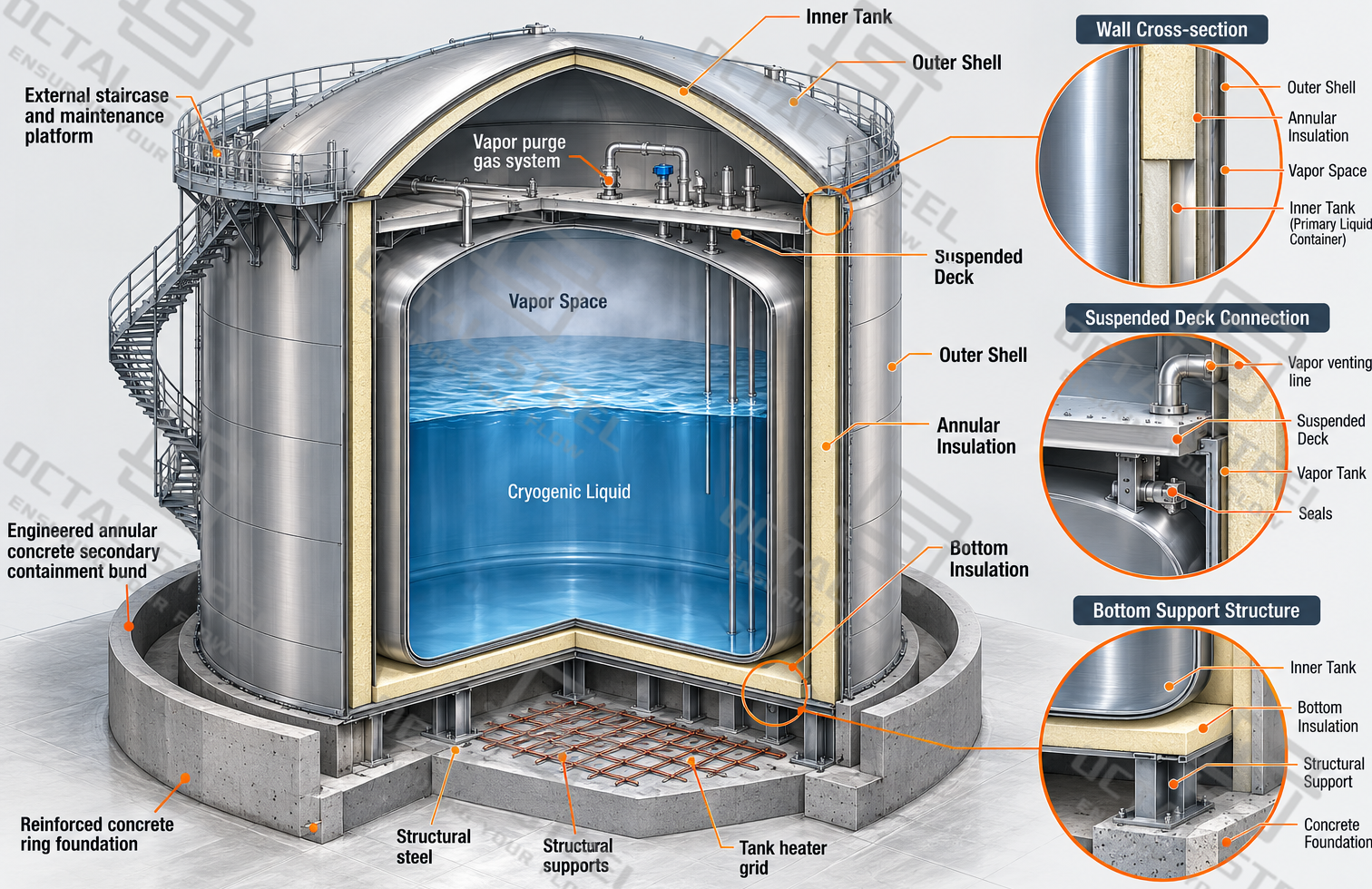
The following specifications describe the principal design options and engineering parameters for large, field-erected cryogenic liquid tanks.
| Parameter | Technical Specification |
|---|---|
| Product | Cryogenic Liquid Tank / Cryogenic Liquid Storage Tank |
| Tank Configuration | Vertical, cylindrical, flat-bottom, double-wall insulated tank |
| Storage Media | Liquid oxygen, liquid nitrogen, liquid argon, LNG, and other compatible refrigerated liquids |
| Reference Tank Capacities | 900, 1,200, 1,500, 3,000 and 6,000 m³ |
| Design Pressure | Low-pressure storage; specified according to the stored medium, operating conditions, and applicable code |
| Operating Temperature | Cryogenic, according to stored liquid |
| Inner Tank Material | Cryogenic-compatible stainless steel or other approved low-temperature material |
| Outer Tank Material | Carbon steel, low-temperature steel or other project-specified construction material |
| Containment Configuration | Single containment or full containment; other configurations subject to project design |
| Roof Structure | Suspended deck, domed roof, or other engineered roof system |
| Insulation | Perlite, foam glass, mineral wool or approved cryogenic insulation arrangements |
| Design Standards | API 620, API 625, EN 14620 or applicable project codes |
| Construction Method | Factory prefabrication and field erection |
| Inspection | Material inspection, dimensional examination, qualified NDT, leak testing and project-specific commissioning tests |
The capacities listed above represent documented engineering project sizes, not a fixed manufacturing range or a standard model series. Final tank diameter, height, shell thickness, insulation thickness, allowable pressure and working volume are established during project design.
Engineering Reference Tank Capacities
| Storage Medium | Reference Capacity | Project / Design Reference |
|---|---|---|
| Liquid Oxygen (LOX) | 6,000 m³ | Two API 620 tanks documented for an integrated steelworks project |
| Liquid Nitrogen (LIN) | 1,500 m³ | Two API 620 tanks documented for the same steelworks project |
| Cryogenic Liquid Storage | 3,000 m³ | Ten large cryogenic tanks documented for an industrial steelworks project |
| Cryogenic Liquid Storage | 900 / 1,200 m³ | Export project with factory prefabrication and project-specific equipment design |
These engineering references illustrate how the storage arrangement changes with project requirements. They should not be interpreted as interchangeable designs: a liquid oxygen tank and a liquid nitrogen tank with the same nominal capacity can require different load calculations, operating provisions and cleaning procedures.
Cryogenic Liquid Storage Tank Design Standards
Large refrigerated liquid tanks require an integrated design approach covering liquid containment, low-temperature material performance, insulation, pressure management, and the structural loads imposed during operation.
The applicable code is determined by tank configuration, design pressure, minimum design temperature, stored medium and jurisdiction.
| Standard | Main Requirements | Application to Cryogenic Tanks |
|---|---|---|
| API 620 | Design and construction of large welded low-pressure storage tanks | Specifies structural design, materials, welding, inspection and testing requirements |
| API 620 Annex Q | Additional requirements for specified low-temperature liquefied gas storage tanks | Covers cryogenic material selection, low-temperature design, welding and testing within its applicable temperature range |
| API 625 | Requirements for refrigerated liquefied gas storage tank systems | Covers containment design, insulation, foundations, safety systems and commissioning |
| EN 14620 | Design and construction of site-built, flat-bottom refrigerated storage tanks | Covers containment types, tank construction, insulation, testing and installation |
| Project-Specific Codes | Additional local regulations and project requirements | Addresses wind, seismic loads, fire safety and site-specific operating conditions |
API 620 covers the structural design and construction of large welded low-pressure tanks, while API 625 addresses the complete refrigerated storage system, including insulation, foundations and containment requirements. EN 14620 provides a corresponding European framework for site-built cryogenic tanks. The applicable standards and low-temperature requirements are selected according to the stored medium, design temperature, operating pressure and tank configuration.
Download:Cryogenic liquid tank design and technical specification guide.pdf
Cryogenic Liquid Tank Types and Containment Designs
The structural arrangement determines how the tank carries liquid loads, accommodates temperature changes, protects the insulation and responds to leakage from the primary liquid container.
Large cryogenic tanks generally include an inner metallic vessel and an external enclosure, but the containment performance depends on the complete design.
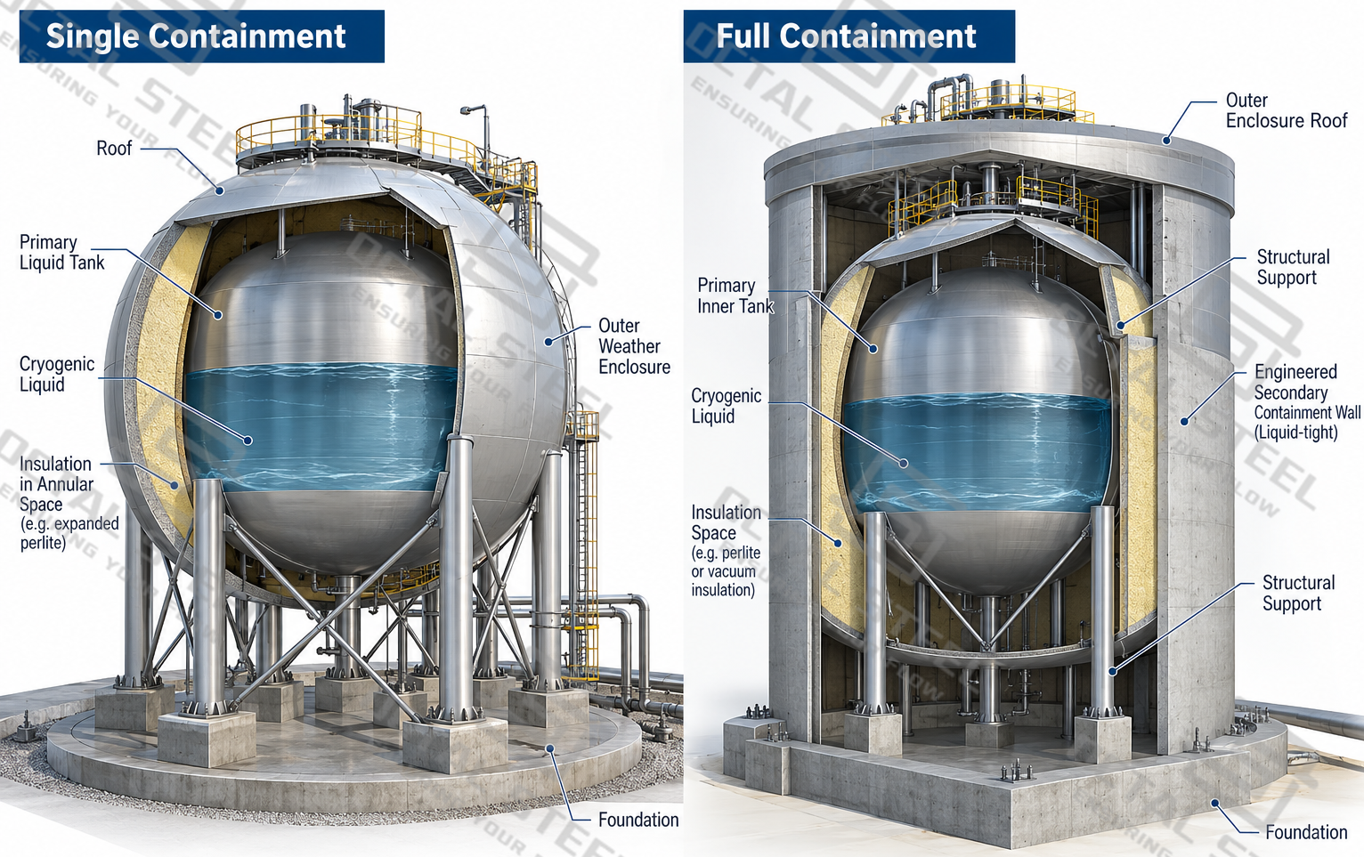
Single Containment Cryogenic Tanks
Single containment tanks use an inner primary tank designed to hold the refrigerated liquid. An external wall and roof may enclose the insulation, protect the structure from weather and maintain the required insulation environment.
The outer enclosure of a single containment design is not automatically capable of retaining the entire liquid inventory after an inner tank failure. External impoundment or another protective arrangement may therefore be required by the design and safety assessment.
Single containment systems may incorporate a suspended deck or a roof supported by the outer tank structure, with construction details governed by the project design.
Full Containment Cryogenic Tanks
Full containment designs incorporate a primary liquid container and a secondary containment structure capable of retaining the liquid following a defined primary containment failure.
The secondary enclosure must also address the associated vapor-control requirements under the governing design basis. Its structure, material selection, penetrations and foundation details are consequently more demanding than those of an ordinary weather-protective outer shell.
Full containment is particularly relevant where the stored inventory, site surroundings and consequence assessment require additional protection against uncontrolled liquid release.
Suspended Deck and Domed Roof Arrangements
A suspended deck is located inside the outer roof structure and helps separate the cold internal region from the warmer roof enclosure. Insulation is installed above or around the deck in accordance with the tank configuration, reducing thermal transfer through the upper part of the system.
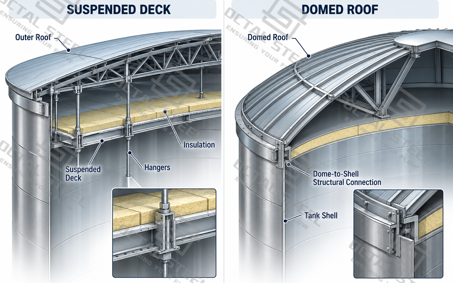
A domed roof provides a curved structural enclosure capable of accommodating the specified roof loads and pressure conditions. Its structural function should be distinguished from the suspended insulation deck.
Roof configuration is selected together with vapor management, insulation, equipment access and erection requirements. The roof shape alone does not determine whether the tank qualifies as single or full containment.
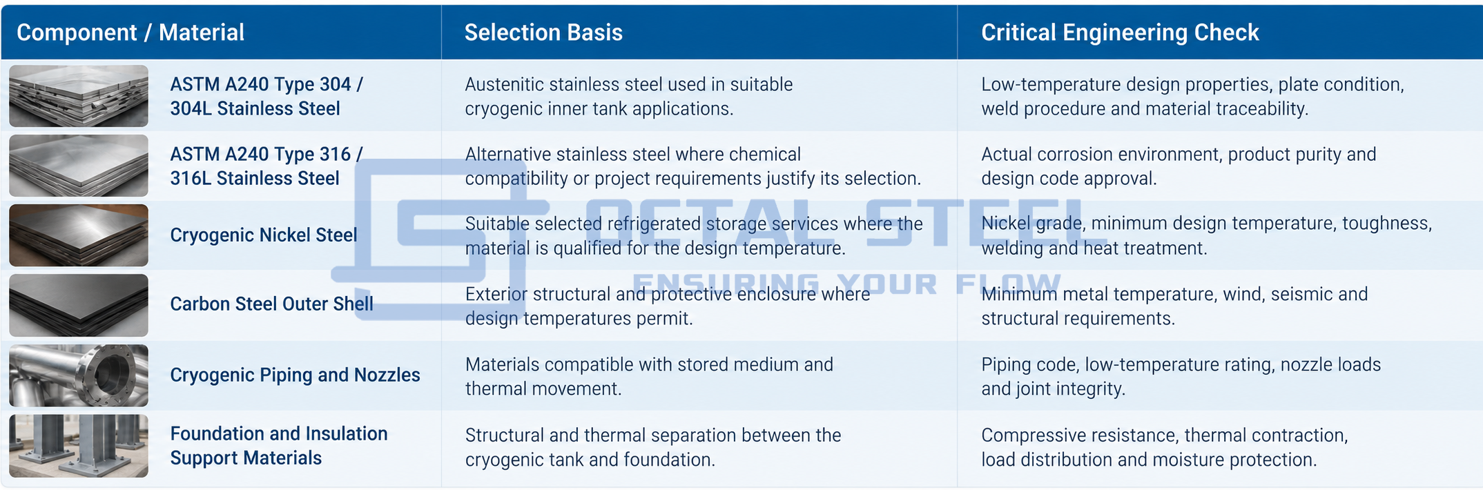
Materials for Cryogenic Liquid Storage Tanks
Cryogenic materials must retain adequate strength and fracture resistance at the minimum design temperature. Temperature gradients during cooldown, differences in thermal expansion, welding performance and compatibility with the stored liquid are important in selecting the inner tank material.
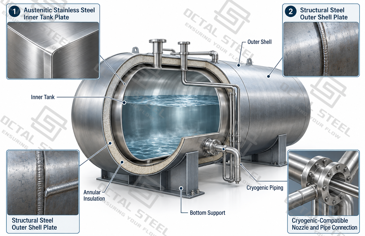
The inner vessel is exposed directly to refrigerated liquid, while the outer enclosure may operate at a different temperature depending on the containment arrangement.
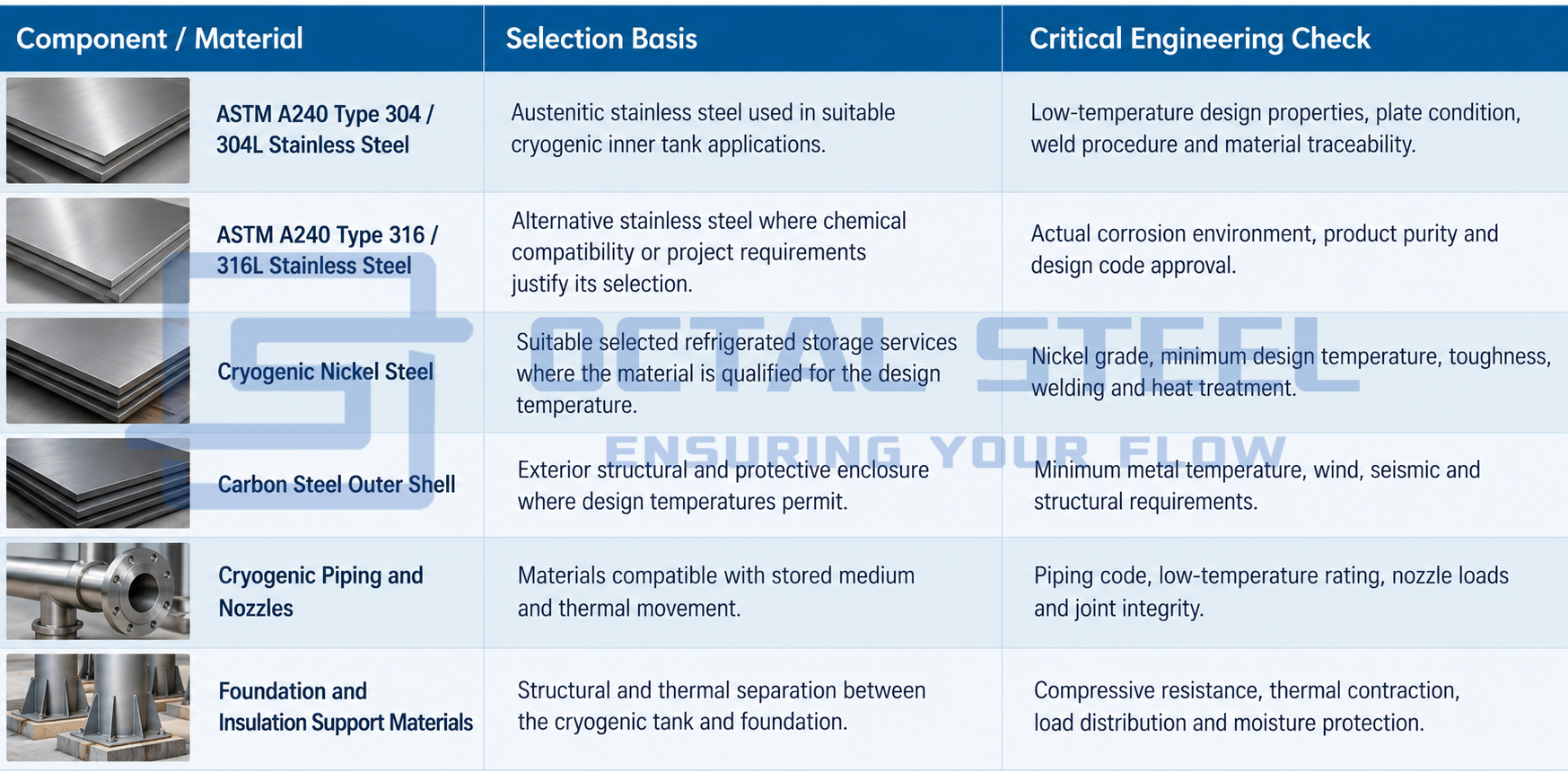
Austenitic stainless steels such as 304L are commonly considered for liquid oxygen, nitrogen and argon storage because of their low-temperature mechanical behavior and weldability.
For liquid oxygen service, material selection must be accompanied by an appropriate oxygen-cleaning and contamination-control program. Components in oxygen service must be assessed for ignition hazards, including potential contamination from oils, greases and incompatible materials.
For projects considering LNG or other refrigerated hydrocarbons, the acceptable use of nickel steels or stainless steels must be evaluated against the design temperature, applicable code and welding requirements. A material accepted for one cryogenic medium is not automatically suitable for another.
Cryogenic Tank Insulation System and Boil-Off Control
Effective insulation limits heat transfer from the surrounding environment into the refrigerated liquid. Uncontrolled heat ingress increases vapor generation and may raise the tank pressure, increase venting requirements or place additional demand on the vapor recovery system.
Large flat-bottom cryogenic tanks use insulation arrangements that differ substantially from those of small vacuum-jacketed pressure vessels. The wall, bottom and roof assemblies may each use different insulation materials because their structural loads and heat-transfer paths are different.
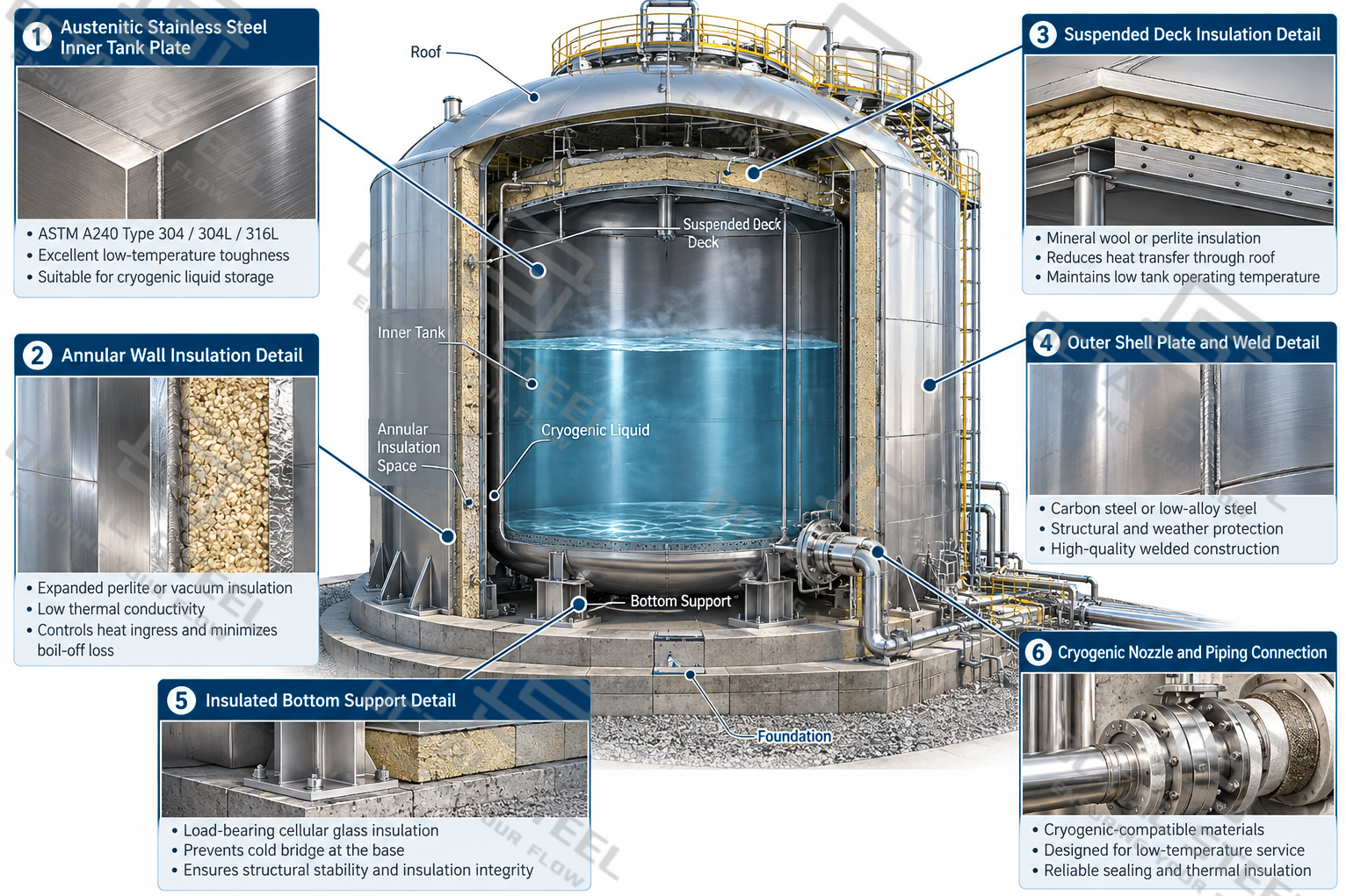
The insulation system must be assessed for settlement, compression, moisture ingress and thermal cycling. For granular or fibrous insulation, installation density and continuity are important to avoiding voids or thermal bridges.
Tank foundations also require special consideration. Depending on local ground conditions and design temperatures, a foundation heating or frost-protection system may be required to prevent excessive ground freezing and associated structural movement.
Heat Ingress and Boil-Off Gas
Even a well-insulated cryogenic tank receives a small amount of heat from its surroundings. This heat can vaporize part of the stored liquid, producing boil-off gas (BOG).
Boil-off performance is influenced by the liquid’s latent heat, insulation design, tank surface area, operating pressure, ambient conditions and product handling frequency.
Boil-off rate is often expressed as a percentage of stored liquid volume or mass per day, but the value cannot be treated as constant across different tank capacities and media.
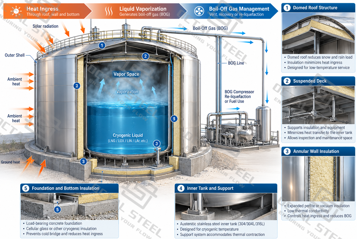
An engineering proposal should therefore state the guaranteed or calculated heat-leak/boil-off basis, including the reference filling level, ambient conditions, operating pressure and applicable performance acceptance criteria.
Cryogenic Liquid Tank Design and Safety Features
A large cryogenic tank must accommodate normal filling, storage, withdrawal and pressure fluctuations, as well as defined abnormal operating conditions.
Safety provisions form part of the engineered storage system and are selected according to the tank hazard assessment and applicable standards.
| Safety / Operating System | Function | Design Consideration |
|---|---|---|
| Pressure Relief System | Protects the tank from excessive internal pressure | Relief capacity, set pressure, discharge location and applicable design scenarios |
| Vacuum Protection | Prevents damaging external differential pressure | Pump-out, condensation, thermal effects and other vacuum scenarios |
| Level Instrumentation | Monitors liquid inventory during filling and withdrawal | Measurement accuracy, alarm settings and overfill prevention |
| Temperature Monitoring | Tracks liquid and structural temperatures | Cooldown control, operating conditions and possible temperature gradients |
| Pressure Instrumentation | Monitors vapor-space pressure | Alarm and control response, redundancy where required |
| Boil-Off Gas Handling | Manages vapor generated during storage and handling | Venting, recovery, recompression or recondensation arrangements |
| Isolation and Emergency Shutdown | Limits uncontrolled transfer or release | Valve accessibility, fail-safe actions and system interfaces |
Liquid oxygen storage requires particular attention to combustible contamination, oxygen enrichment hazards and equipment compatibility. Liquid nitrogen and argon introduce oxygen-deficiency hazards if released into occupied or poorly ventilated spaces.
Cool-down procedures are also important. Introducing cryogenic liquid too rapidly may produce steep thermal gradients and differential contraction across tank components, nozzles and connected piping.
The required rate of cooling, permitted temperature differences and operating sequence are established through the approved commissioning procedure rather than a single universal temperature-drop limit.
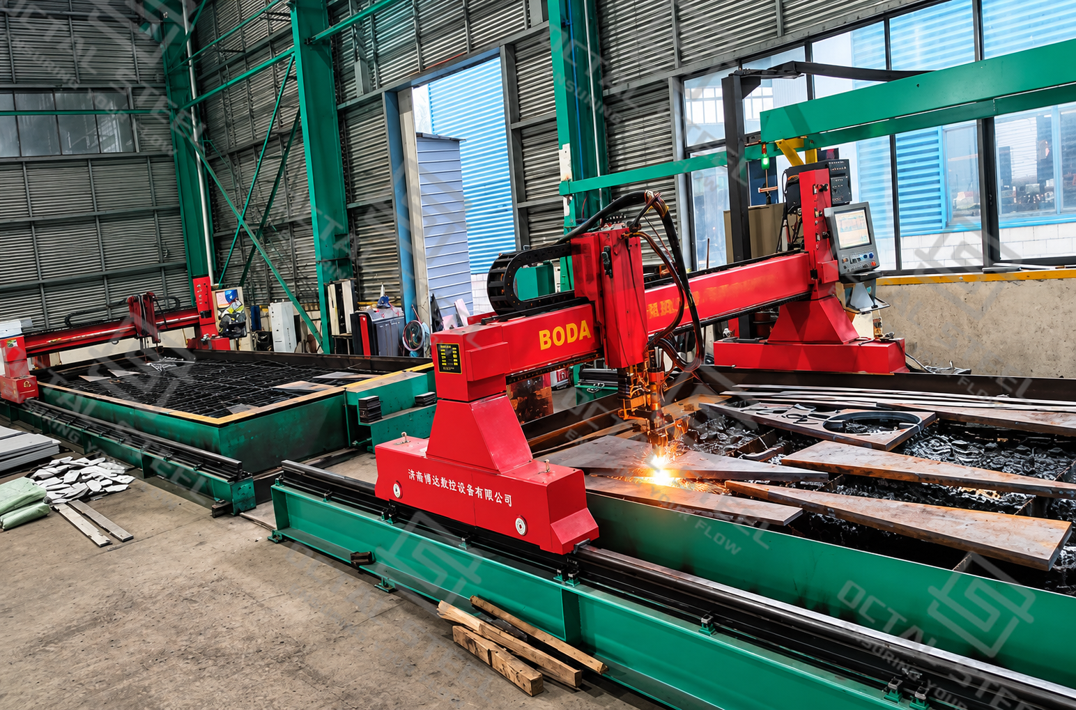
Cryogenic Liquid Tank Manufacturing and Prefabrication
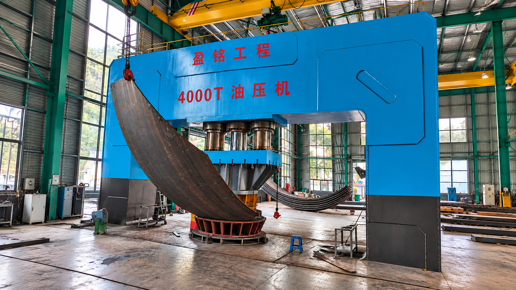
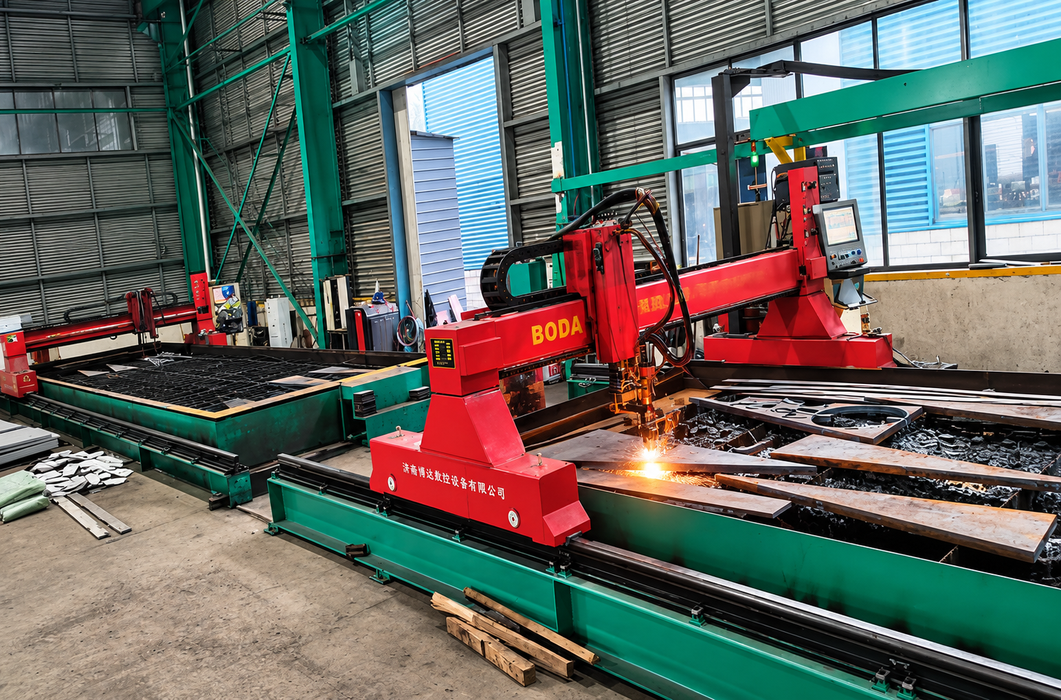
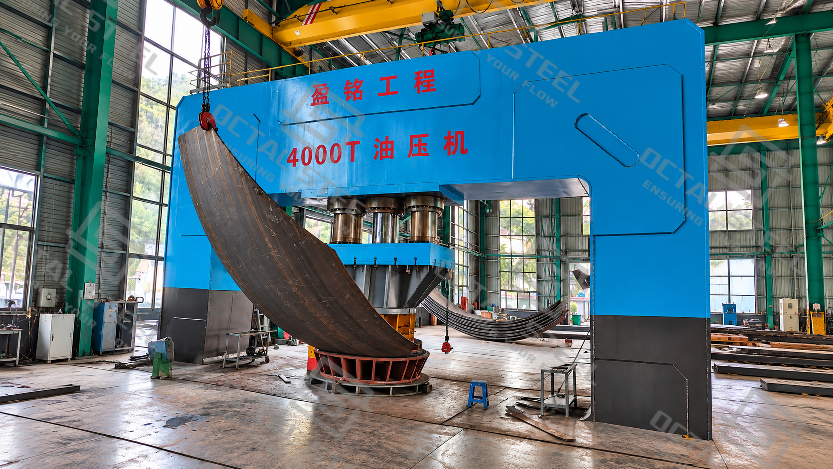
Large cryogenic tanks are normally divided into components suitable for controlled factory fabrication and subsequent field installation. Factory work includes steel plate inspection, cutting, edge preparation, forming, machining and prefabrication of selected structural components.
The objective is to transfer accurate, traceable components to the construction site while minimizing dimensional mismatch and welding rework during erection.
Manufacturing Process
Raw Material Inspection → Plate Marking and Cutting → Edge Preparation → Plate Forming → Dimensional Inspection → Component Prefabrication → Surface Preparation → Identification and Packing
| Safety / Operating System | Function | Design Consideration |
|---|---|---|
| Pressure Relief System | Protects the tank from excessive internal pressure | Relief capacity, set pressure, discharge location and applicable design scenarios |
| Vacuum Protection | Prevents damaging external differential pressure | Pump-out, condensation, thermal effects and other vacuum scenarios |
| Level Instrumentation | Monitors liquid inventory during filling and withdrawal | Measurement accuracy, alarm settings and overfill prevention |
| Temperature Monitoring | Tracks liquid and structural temperatures | Cooldown control, operating conditions and possible temperature gradients |
| Pressure Instrumentation | Monitors vapor-space pressure | Alarm and control response, redundancy where required |
| Boil-Off Gas Handling | Manages vapor generated during storage and handling | Venting, recovery, recompression or recondensation arrangements |
| Isolation and Emergency Shutdown | Limits uncontrolled transfer or release | Valve accessibility, fail-safe actions and system interfaces |
Plate edges and weld preparations must be compatible with the approved joint design. Formed shell plates are checked against the required radius and curvature tolerances before being released for shipment.
For stainless steel components, fabrication controls should prevent carbon-steel contamination and preserve the specified surface condition. Cutting and grinding equipment, handling procedures and cleaning materials require appropriate segregation.
Cryogenic Liquid Tank Field Erection and Installation
Large-capacity cryogenic liquid tanks are assembled on-site using prefabricated steel plates and structural components. Field erection covers foundation acceptance, tank bottom installation, shell assembly, roof construction, inner tank welding, insulation and final system integration.
Field Erection Process:
Foundation Inspection → Bottom Plate Installation → Shell Erection → Roof Assembly → Inner Tank Welding → Inspection → Insulation Installation → System Integration
Foundation and Tank Assembly: Construction begins with checking foundation elevation, levelness and structural support. Bottom plates are positioned and welded, followed by shell erection using approved lifting arrangements. Shell roundness, verticality and weld alignment are controlled throughout installation to prevent accumulated dimensional errors.
Roof Assembly and Welding: The outer roof and suspended deck, where applicable, are assembled according to the approved erection sequence. Inner tank welding follows qualified welding procedures, with attention to joint fit-up, thermal distortion and contamination control. Required weld examinations are completed before inaccessible areas are enclosed or insulated.
Insulation and System Installation: Load-bearing bottom insulation, wall insulation and roof insulation are installed according to the approved design. Piping, valves, access platforms and instrumentation are integrated after the relevant construction inspections. Final checks cover nozzle alignment, piping connections, insulation continuity and readiness for commissioning.
Quality Control and Inspection
Quality control for cryogenic liquid tanks focuses on material traceability, dimensional accuracy, weld integrity, leak tightness and insulation quality. Inspection follows the applicable construction code and approved Inspection and Test Plan (ITP), with records maintained throughout fabrication and field erection.
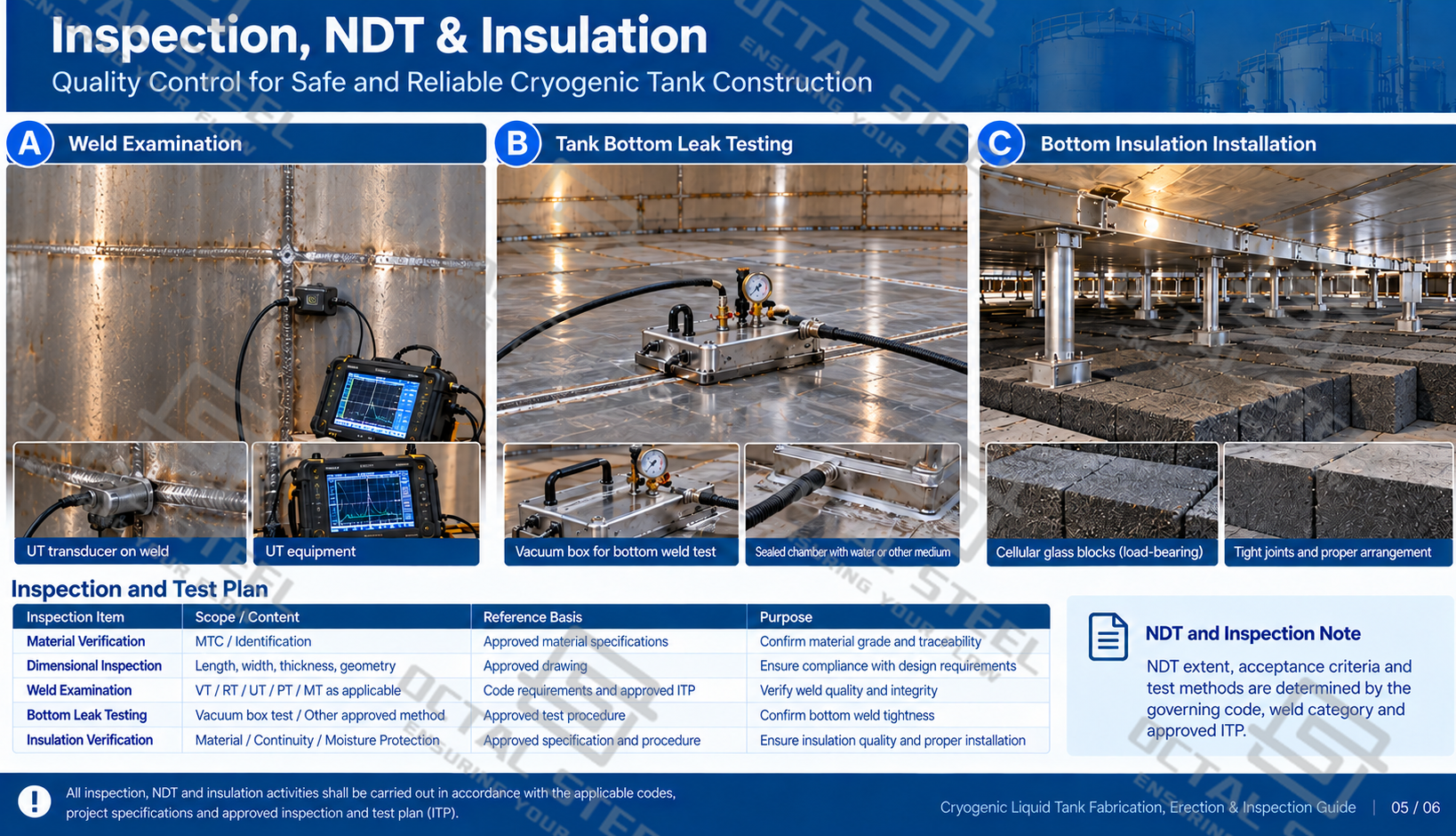
Inspection coverage and acceptance criteria vary with the tank design, weld category and applicable standard. Material traceability, welding records and test results are compiled into the final quality dossier to support project acceptance and future maintenance.
Applications of Cryogenic Liquid Storage Tanks
Cryogenic liquid tanks are integral to large air separation units where liquid oxygen, nitrogen and argon are produced, stored and transferred to distribution or vaporization systems. During plant output fluctuations, a storage tank provides liquid inventory that can be managed separately from the instantaneous production rate. The selection of storage volume must account for production capacity, downstream demand, delivery arrangements and the required reserve period.
Steelmaking facilities use bulk liquid oxygen storage to support oxygen supply systems for furnaces and other metallurgical processes. Large liquid oxygen inventories allow the facility to balance gas-production equipment with plant consumption, while pressure control, oxygen cleanliness and reliable liquid withdrawal remain critical during operating changes. Liquid nitrogen storage may serve purging, blanketing and industrial gas distribution, with piping arrangements designed for the specified flow and temperature conditions.
Chemical and petrochemical plants also use refrigerated storage systems for gases and other low-temperature liquids required by production processes. These installations may involve continuous liquid withdrawal, transfer between storage and process equipment, or periodic loading and unloading. Tank materials, containment, thermal insulation and safety instrumentation are selected according to the stored medium and the consequences of a potential release.
Download:Cryogenic liquid tank fabrication field erection and inspection guide.pdf
Why Choose Octal Steel
Cryogenic liquid storage projects involve more than tank shell fabrication. Material selection, insulation, field assembly, inspection requirements and the interfaces between the storage vessel and plant systems must be established before manufacturing begins.
Octal Steel’s industrial equipment sourcing and project coordination approach emphasizes clear technical requirements, material documentation and inspection arrangements. For cryogenic tank inquiries, the proposed configuration can be evaluated against the specified capacity, stored medium, applicable codes, construction location and project scope.
Particular attention is given to defining the supply boundary between prefabricated tank components, insulation, valves, instrumentation, site construction and commissioning. This helps establish which inspections and engineering documents must accompany the equipment and which activities remain within the site contractor’s scope.
Material certificates, approved drawings, welding records, inspection reports and project documentation requirements can be incorporated into the procurement specification and agreed with the responsible manufacturer before order execution.
FAQ
What information is needed to specify a cryogenic liquid tank?
The inquiry should identify the stored medium, required gross and working capacities, operating and design pressures, minimum design temperature, filling and withdrawal rates, applicable code, site conditions and preferred containment arrangement. The specified construction and commissioning scope should also be included.
How much does a cryogenic liquid storage tank cost?
Pricing is established from the tank capacity, containment system, materials, insulation, engineering requirements and site construction scope. Foundations, instrumentation, transportation, erection and commissioning can significantly change the total project cost, so a meaningful quotation requires a defined technical specification.
Can a cryogenic liquid tank store different liquefied gases?
Different cryogenic liquids require different material, cleanliness, temperature, pressure and safety provisions. A tank originally designed for one product should not be reassigned to another without a formal engineering review and any necessary modifications, cleaning, testing and approvals.
What affects the boil-off rate of a cryogenic storage tank?
Heat ingress, insulation performance, tank geometry, ambient conditions, operating pressure, fill level and product transfer operations influence vapor generation. The boil-off basis should be stated in the tank performance specification under defined reference conditions.