Your Responsible Supplier Partner for Oil and Gas Products.

Steel Columns
Recent Products


Rencent Articles



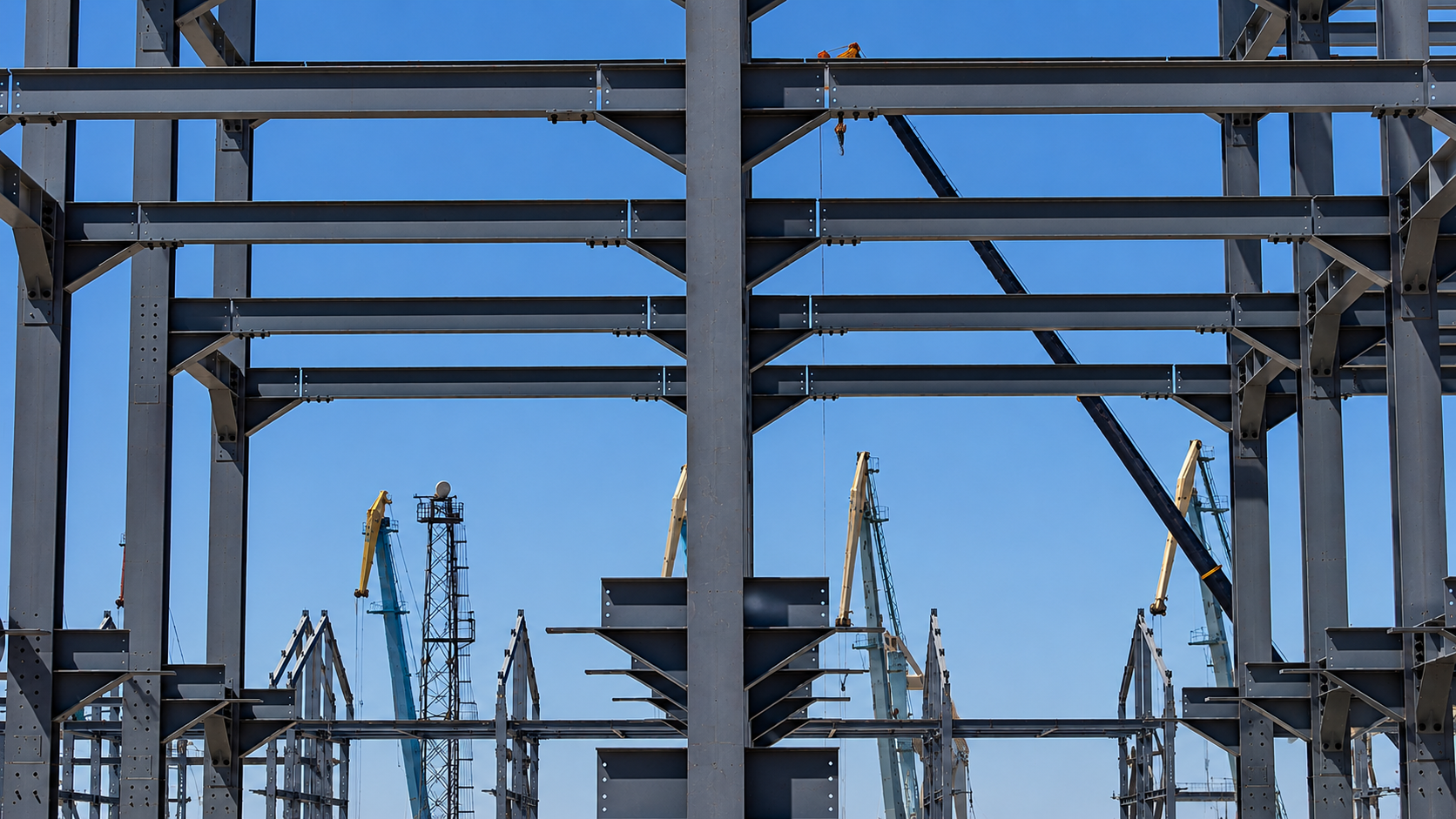
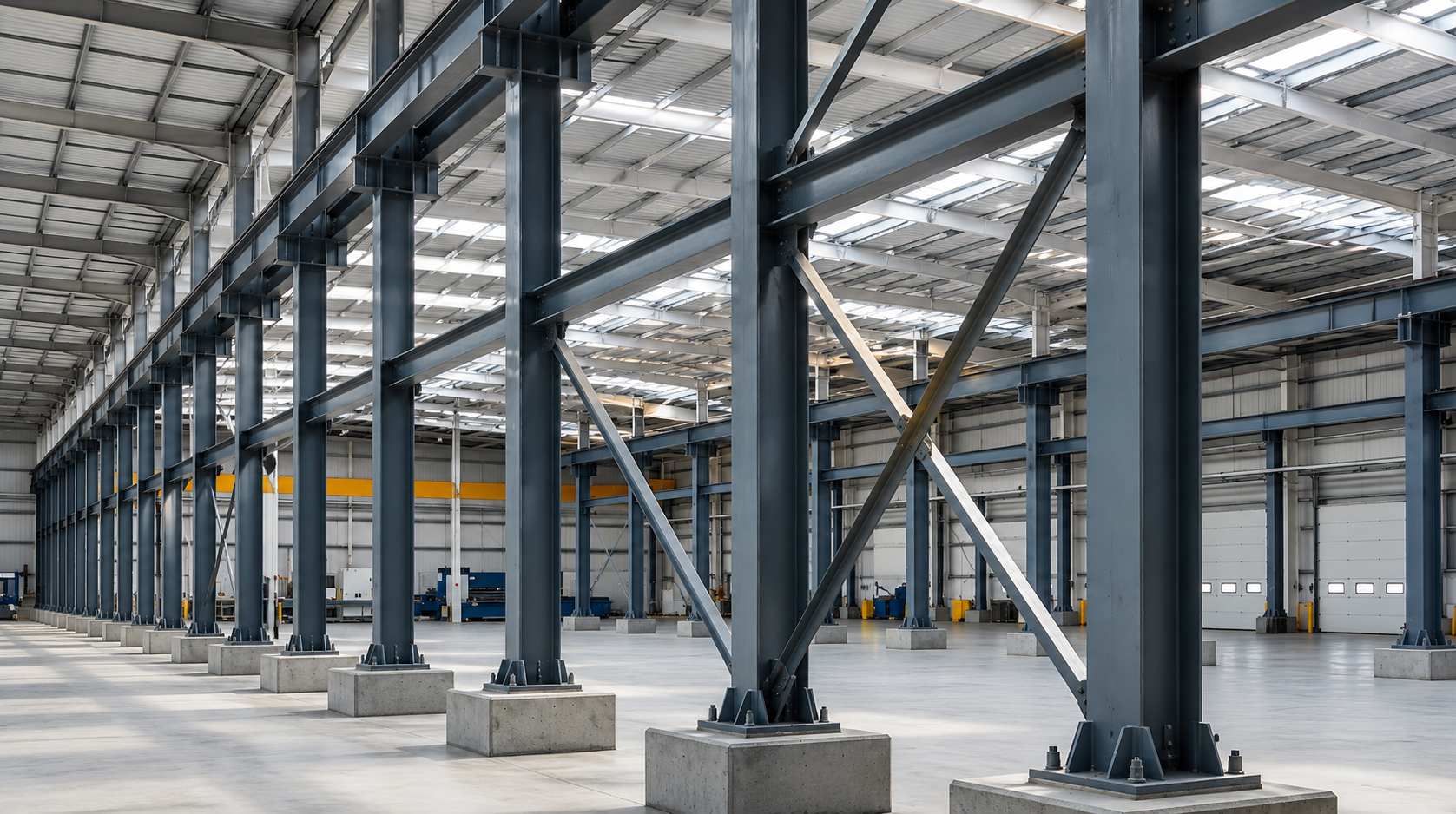
Steel Columns
Column Types: Wide flange, H-section, HSS, tubular and built-up steel columns
Material Grades: ASTM A36, A572, A992, A588 or project-specified grades
Finished Lengths: Fabricated according to approved column schedules and drawings
Connections: Base plates, cap plates, stiffeners, brackets and column splices
Delivery: Complete columns or marked erection segments for site assembly
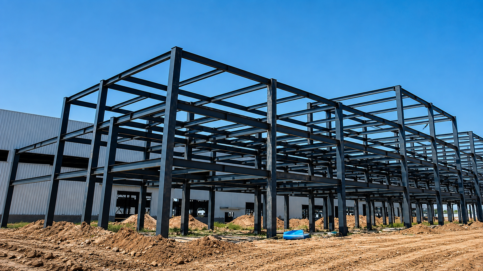
Steel columns are vertical load-bearing members that receive reactions from structural steel beams, roof trusses, floor systems, crane supports and equipment platforms, then transfer those forces into the foundation. A steel column may carry axial compression alone, but most columns in actual buildings also resist bending caused by frame action, connection eccentricity, wind, seismic effects or unequal loading on adjoining beams.
Structural steel columns are manufactured from rolled sections, hollow structural sections, tubular members or welded plates. The correct column cannot be selected from height or nominal section depth alone. Section geometry, steel grade, unsupported length, restraint direction, connection levels, base condition, erection sequence and corrosion exposure must all correspond with the approved structural design.
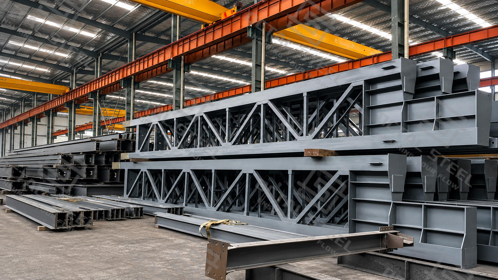
Octal Steel supplies standard and fabricated steel columns according to approved column schedules, material specifications and fabrication drawings. The scope may include cutting, drilling, welded base plates, cap plates, stiffeners, beam-connection plates, brackets, column splices, surface treatment, piece marking, inspection documents and export packing. The column, its connections and its adjoining structural members are reviewed as one fabrication package rather than as unrelated steel items.
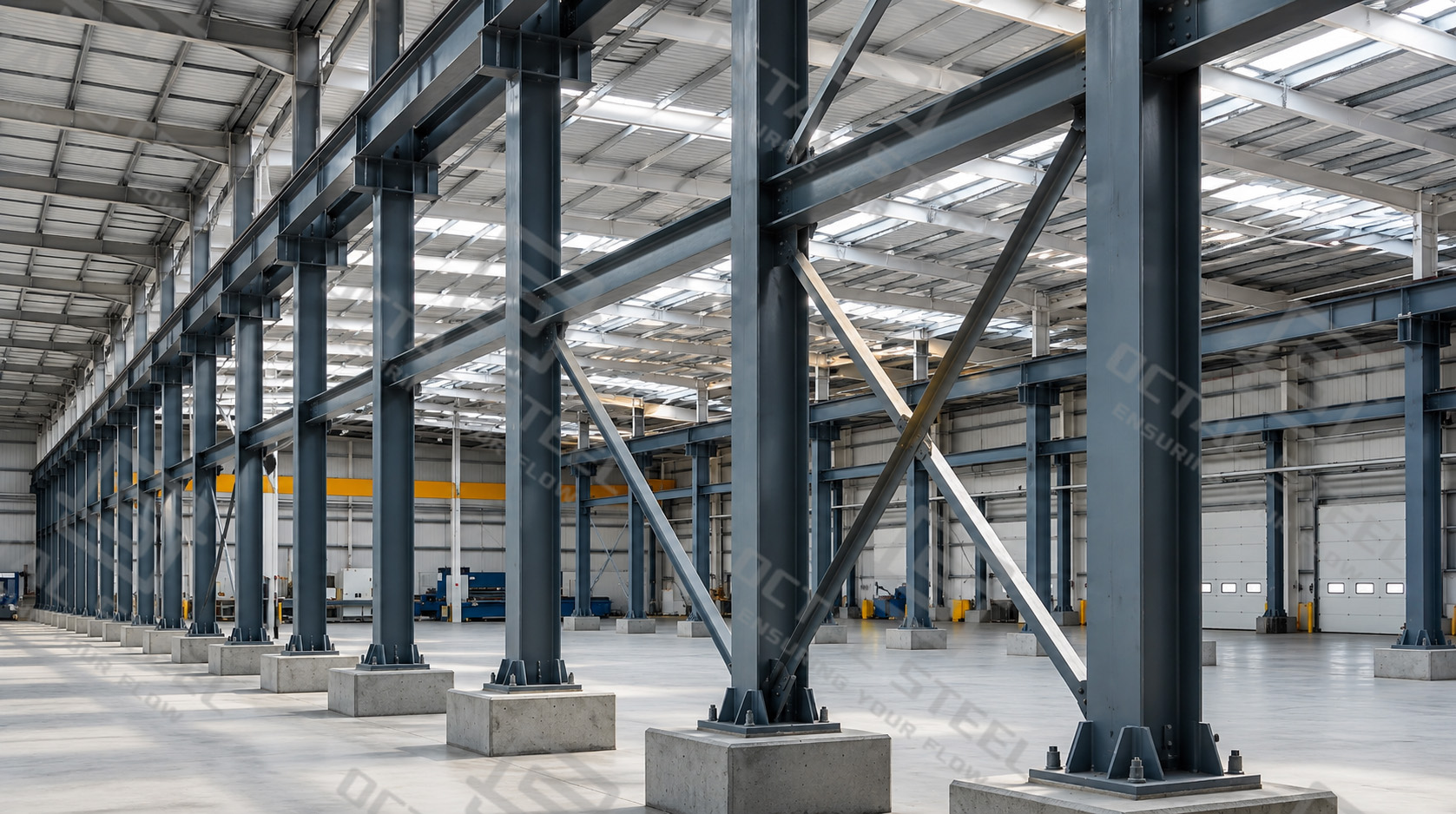
Steel Column Supply Range
| Product Item | Available Scope |
|---|---|
| Column Types | Rolled wide flange columns, H-section columns, HSS steel columns, circular tubular columns, welded box columns and built-up structural steel columns |
| Section Supply | Standard rolled structural sections or project-specific fabricated sections |
| Material Specifications | ASTM A992, ASTM A572, ASTM A36, ASTM A588 and other project-specified structural grades where applicable |
| Finished Length | Cut and fabricated according to the approved column schedule and erection segmentation |
| Main Components | Column shaft, base plate, cap plate, splice plates, stiffeners, brackets, shear plates, connection cleats and temporary erection attachments |
| Fabrication | Cutting, end preparation, drilling, slotting, coping, plate assembly, welding, straightening and trial fit-up where required |
| Connection Form | Shop-welded components, bolted field connections or combined shop-welded and site-bolted arrangements |
| Surface Condition | Mill finish, blasted surface, shop primer, multi-layer coating or galvanizing where technically suitable |
| Inspection | Material verification, dimensional inspection, straightness control, hole-position checks, weld inspection and specified NDT |
| Identification | Individual piece marks linked to fabrication drawings, inspection records and packing lists |
| Delivery Form | Complete columns or marked erection segments arranged according to transport and site-access limits |
Changing from a rolled section to a welded section, altering the column-splice level or moving a bracket cannot be treated as a purchasing substitution because these changes may affect stiffness, load transfer, connection forces and erection stability.
How Steel Columns, Beams and Trusses Work Together
Steel columns, beams and trusses perform different functions but operate as one structural system. Columns provide the main vertical support. Beams span between columns and carry floor, platform, wall or roof loads. Steel trusses use triangulated members to carry roof loads across longer clear spans where a conventional beam would become too deep or heavy.
In a typical industrial building, roof sheets first transfer load to purlins. The purlins deliver these loads to the steel trusses, and the trusses transfer their end reactions into the columns. Floor beams, crane beams, equipment platforms and wall framing may also connect to the same columns. The columns collect these reactions and transfer them through the base plates and anchor system into the foundation.
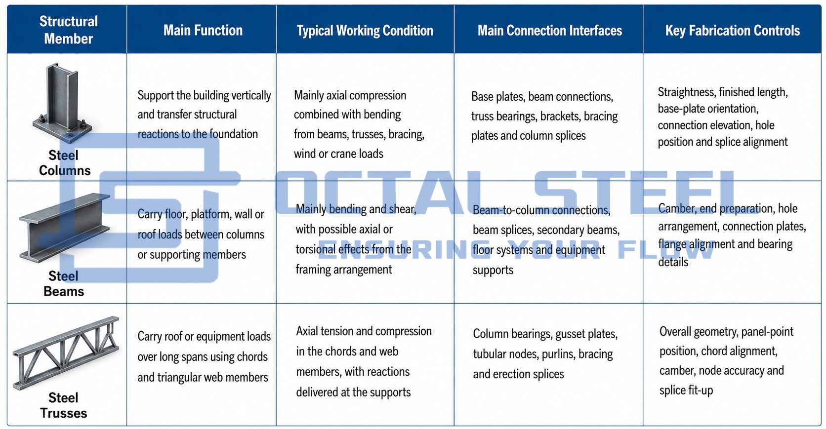
The three members cannot be specified independently. A truss reaction affects the column section and its bearing detail. A beam connection affects the column orientation, stiffeners and local reinforcement. Column spacing also determines the span and arrangement of the beams or trusses. For this reason, the column schedule, beam drawings, truss layout and connection details must be reviewed together before fabrication.
For example, changing a roof beam to a deeper steel truss may reduce the number of internal columns, but it also changes the support reactions, truss bearing geometry, column-top connection and erection sequence. Similarly, moving a beam connection or crane bracket changes where the load enters the column and may require different stiffeners or a heavier column section.
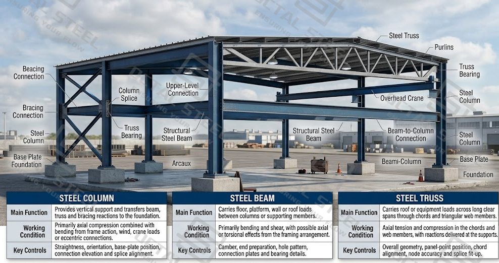
A coordinated structural steel package should therefore confirm:
- the load carried by each beam or truss;
- the grid position and orientation of each column;
- the elevation of beam, bracket and truss connections;
- the bearing, splice and bracing details;
- which connections are shop-welded and which are completed on site;
- the piece marks used across drawings, fabrication and packing.
When these interfaces are coordinated, the beams and trusses fit the column connections correctly, the column base plates match the foundation, and the complete steel frame can be erected without unplanned cutting, drilling or connection modification.
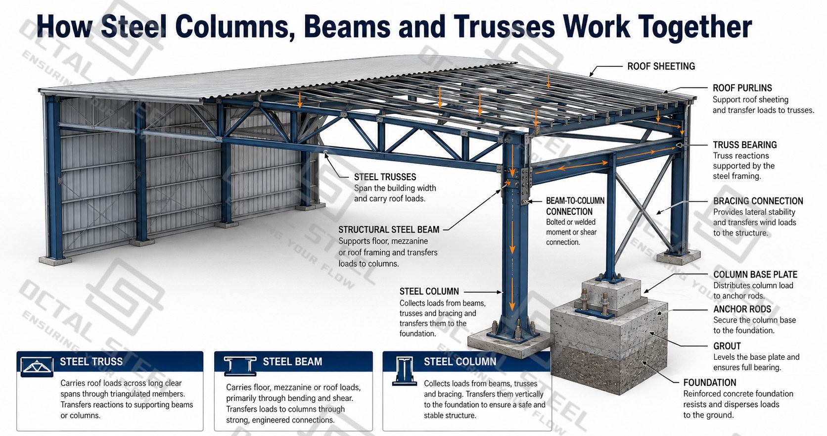
How a Steel Column Transfers Loads
The basic load path in a steel-framed building is:
Roof, floor or equipment load → beam or truss → connection → steel column → base connection → foundation
Beams and trusses deliver reactions to the column at defined connection levels. These reactions create axial force and may also introduce bending moments. Bracing members, portal-frame action and moment connections can add horizontal forces and bending about either principal axis.
The column transfers these combined actions downward through its section and any intermediate splices. At the bottom, the base plate distributes compression into the grout and concrete foundation. Anchor rods and other base-connection components transfer the forces assigned to them by the approved design, which may include shear, uplift or moment as well as erection restraint.
The behaviour of the column therefore depends on more than steel strength. Unsupported length, weak-axis restraint, frame stiffness, connection eccentricity, local bracket loading and base restraint all influence the final section and connection arrangement. AISC treats column base connections as a separate design subject because they form the critical interface between the steel frame and the foundation.
Types of Steel Columns
Steel column types should be identified by both section form and manufacturing method. Commercial descriptions such as “H column” or “steel tube column” are not sufficient for fabrication unless the complete section designation, dimensions, material grade and connection details are provided.
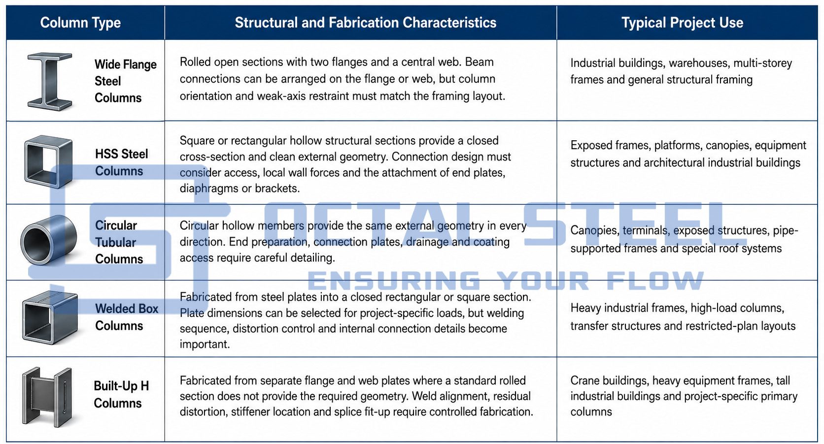
A section type should not be selected only because it appears compact or easy to obtain. The final choice must account for axial load, bending about both axes, connection arrangement, unbraced length, fire-protection requirements, coating access and transport limits.
Steel Column Sizes and Fabrication Dimensions
Steel column size is defined by the complete structural section, not only by the overall depth or column height. Each column must be linked to an approved column schedule showing its section designation, steel grade, finished length, grid position and orientation in the building frame.
For rolled wide-flange and H-section columns, the section designation identifies the flange, web and overall profile used for material purchasing. For HSS steel columns, the drawing must state the outside width and depth, wall thickness, steel grade and applicable product standard. Circular tubular columns require the outside diameter and wall thickness. Built-up columns require complete plate dimensions, weld details and the locations of stiffeners or internal diaphragms.
The finished fabrication dimensions include all features that determine site fit-up. These normally cover the distance between the base plate and column top, beam-connection elevations, bracket positions, splice levels, cap-plate orientation and bolt-hole locations. The workshop checks these dimensions from common drawing reference points so that the column matches the foundation, beams and adjoining structural members during erection.
A column can have the correct section and still be unusable when its base plate is rotated, a bracket is placed at the wrong elevation or a splice-hole pattern does not match the next segment. For this reason, section identification and finished connection geometry are inspected together before surface treatment and shipment.
Steel Column Base Plates and Connection Details
Steel column connections transfer loads between the column, beams, bracing members and foundation. Their position and orientation must follow the approved structural and erection drawings because even a small connection error can prevent installation or change the intended load path.
- Column Base Plates
The base plate connects the steel column to the concrete foundation. It distributes compression over the supporting concrete and provides the required interface with the anchor rods, grout and erection-leveling arrangement.
Before fabrication, the base-plate drawing is checked against the approved foundation and anchor-rod layout. The workshop confirms the plate orientation, anchor-hole pattern, column position on the plate and any required stiffeners or shear-transfer components. These checks prevent common site problems such as anchor rods not entering the holes, the column facing the wrong direction or the beam connections being rotated away from their required grid lines.
The base plate and column shaft are assembled in a controlled position before welding. After welding, the fabricator checks plate flatness, column alignment, hole locations and the relationship between the base plate and the column centreline. The completed assembly must fit the actual foundation arrangement without site cutting or unauthorized hole modification.
- Beam, Bracket and Bracing Connections
Beam-connection plates, seats, brackets and bracing attachments are installed at the elevations and faces shown on the fabrication drawing. Their location is measured from defined column reference points rather than from the cut end of an unfinished member.
A beam may connect to the column flange, web or an attached plate. The connection arrangement must provide the required load path while leaving enough access for field bolts, welding, coating and inspection. Brackets supporting crane beams, platforms or equipment also require accurate elevation and reinforcement because they introduce concentrated forces directly into the column.
The fabricator checks the connection face, hole pattern, plate projection and erection clearance against the adjoining beam or bracing drawing. This prevents a correctly fabricated column from arriving on site with connection plates that face the wrong direction or interfere with other structural members.
- Column Splices
Column splices are used when the complete column is too long or heavy for transportation and erection. The approved splice level divides the column into manageable segments while maintaining the required structural continuity.
Matching segments are identified as one assembly set. Before shipment, the fabricator checks their orientation, contact surfaces, bolt-hole alignment and the fit of splice plates. Where trial assembly is required, the segments are temporarily connected in the workshop to confirm that the column can be aligned during erection.
The splice position cannot be moved only to simplify packing. A different splice level may change the forces in the connection, interfere with beam framing or remove the access needed for bolt installation and site welding.
Download:Steel_Column_Types_Dimensions_Connections.pdf
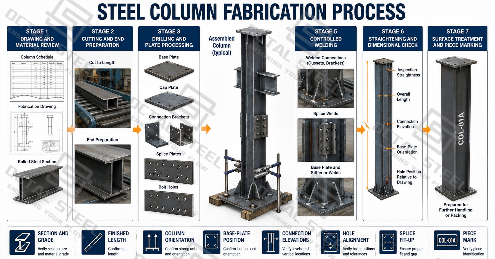
Steel Column Fabrication Process
Fabricated steel columns are produced from coordinated shop drawings rather than from a general section list.
- Drawing review and material identification
The column schedule, section designation, steel grade, connection drawings, surface requirements and piece marks are checked before material allocation. Each main section and plate must remain linked to its material documentation. - Cutting and end preparation
Rolled sections, HSS members and plates are cut to the required fabrication length. Weld bevels, slots, copes and access openings are prepared according to the connection geometry. - Drilling and plate processing
Anchor holes, splice holes, beam-connection holes and erection holes are drilled or machined before final assembly where practical. Base plates, cap plates, stiffeners and brackets are processed to their approved dimensions. - Assembly and alignment
The column shaft is positioned with its plates and attachments in the correct orientation. Connection levels, plate squareness and shaft alignment are checked before final welding. - Controlled welding
Base plates, built-up sections, brackets and stiffeners are welded using the approved fabrication procedure. Welding sequence is controlled to reduce angular distortion, bowing and rotation of connection plates. - Straightening and dimensional inspection
Overall length, straightness, section alignment, base-plate orientation, bracket levels and hole positions are checked against the final fabrication drawing. Matching splice components may be trial-fitted where required. - Surface treatment, marking and packing
After inspection release, columns receive the specified surface preparation and protective system. Piece marks and erection references are kept visible, and loose splice plates, bolts and accessories are packed against the same erection sequence.
This process is consistent with the broader OCTAL structural-steel workflow of drawing breakdown, cutting, drilling, jig assembly, controlled welding, straightening, trial fit-up, coating, marking and shipment preparation.
Industrial Applications of Steel Columns
| Application | Column Working Condition | Main Project Controls |
|---|---|---|
| Manufacturing Plants | Columns receive roof, crane, platform, duct and equipment reactions while maintaining production and maintenance clearances. | Crane brackets, concentrated loads, vibration, service interfaces and column-base forces |
| Warehouses and Logistics Buildings | Repeated steel building columns create clear storage bays and support roof framing above racks, conveyors and handling routes. | Bay spacing, rack clearance, sprinkler routing, roof drainage and base-plate repetition |
| Multi-Storey Steel Frames | Columns transfer reactions from several floor levels and are commonly divided by erection splices. | Floor elevations, beam-connection levels, splice alignment, fire protection and erection stability |
| Crane and Heavy Industrial Buildings | Columns support crane brackets and may carry repeated vertical and horizontal crane reactions in addition to building loads. | Bracket reinforcement, fatigue-sensitive details, frame stiffness and connection inspection |
| Equipment Platforms and Pipe Racks | Steel support columns carry localized equipment, vessel, piping and maintenance-platform loads. | Bracket levels, piping clearance, thermal movement interfaces and access for inspection |
| Canopies, Terminals and Covered Structures | HSS or tubular columns may remain exposed while supporting roof beams, trusses and lateral framing. | Visible connection quality, drainage, coating, base detailing and erection alignment |
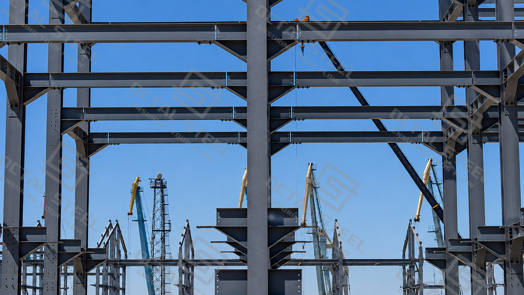
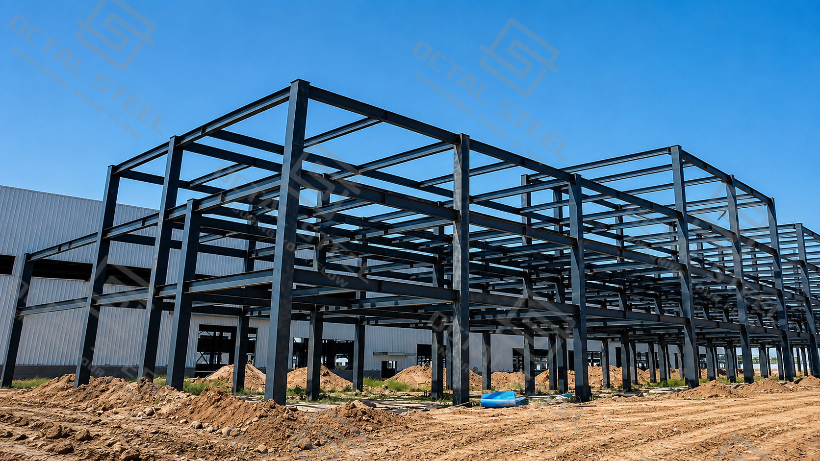
The building type alone does not provide enough information to select or fabricate a steel column. For example, two columns in the same warehouse may have the same height but carry different roof-beam reactions, mezzanine loads, crane loads or bracing forces. Before quotation and fabrication, the approved drawings must identify the members supported by each column, the elevation and direction of incoming loads, the column orientation, unsupported lengths, base restraint, beam and bracing connections, and any required erection splice. These inputs determine the column section, steel grade, base plate, stiffeners, connection plates, hole positions and delivery segmentation. Without this information, a supplier can quote only the basic steel section, not a finished structural steel column ready for installation.
Information Required for Steel Column Fabrication
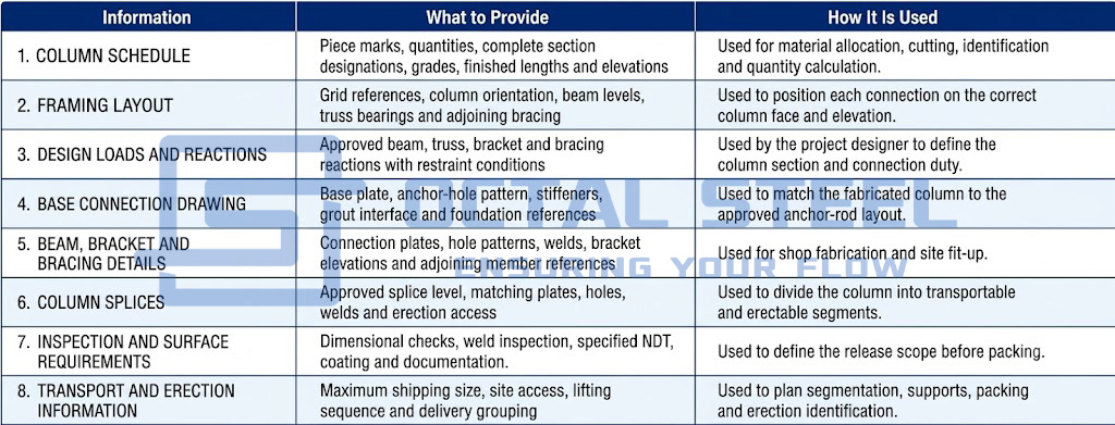
A six-metre length is only the starting point for a steel column enquiry. In an actual warehouse project, one six-metre column may support only the roof beams, while another column of the same height may also carry a mezzanine, wall bracing or crane-beam reactions. Their sections, base plates and connection details will therefore be different.
At the quotation stage, the buyer can send the structural column schedule together with the available framing and connection drawings. These documents normally show the proposed column section, steel grade, quantity, finished elevation, beam and bracing locations, base-plate arrangement and required surface treatment. Octal can then calculate the steel weight and include the actual drilling, plates, stiffeners, welding and coating work in the quotation.
Before fabrication starts, the final approved drawings must confirm which face each beam connects to, where brackets and splices are located, and how the base plate matches the foundation anchor rods. The workshop uses these references to manufacture a finished column that can be erected directly, rather than supplying only a six-metre length of structural steel.
Inspection and Traceability of Fabricated Steel Columns
Inspection confirms that each fabricated steel column matches its approved material, geometry, connection details and identification before shipment.
The main release checks normally cover:
- Section designation and steel grade
- Material heat or batch traceability
- Finished column length
- Straightness and out-of-plane alignment
- Flange, web or HSS orientation
- Base-plate size, position and rotation
- Anchor-hole arrangement
- Beam-connection and bracket elevations
- Splice-hole alignment and matching components
- Weld condition and specified NDT
- Surface preparation and coating condition
- Piece marks and packing references
A practical traceability chain is:
Approved fabrication drawing → material heat or batch → column piece mark → dimensional and weld records → surface record → packing list → shipment release
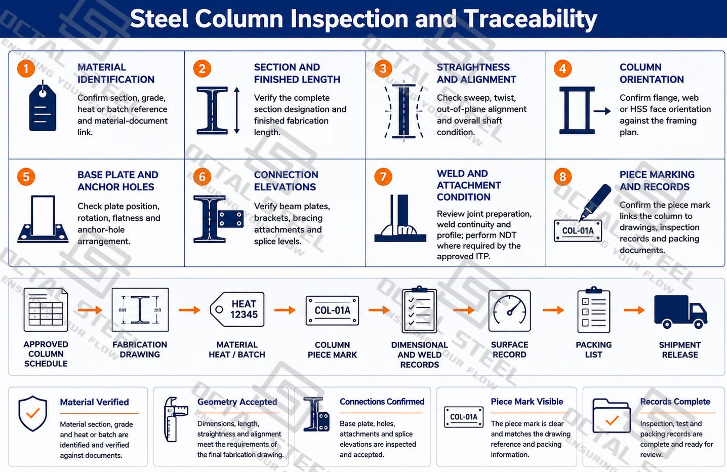
For site installation, the most important result is not only that the column uses the correct steel section. Every base plate, hole pattern, bracket, splice and identification mark must correspond with the final erection drawing. The OCTAL beam page follows the same principle by linking material documents, fabrication drawings, inspection records and packing lists through one consistent piece-mark system.
Surface Protection and Shipment
Steel columns may be supplied with mill finish, blasted surface, shop primer, a specified multi-layer coating or galvanizing where the member geometry and connection details allow proper processing.
The protective system must be selected for the actual exposure and maintenance plan. Exterior moisture, industrial chemicals, coastal atmosphere, concealed crevices and water-trapping details affect the required treatment. Coating or galvanizing does not correct poor drainage, inaccessible joints or damaged site areas.
Where fire resistance is required, the structural column forms part of a specified fire-protection system. Intumescent coating, spray-applied protection, board encasement or concrete encasement must be coordinated with connection access and erection work. Structural steel should not be described as inherently fireproof.
For shipment, finished columns are supported to prevent permanent bending and damage to base plates, brackets and coatings. Tall columns may be supplied as approved erection segments. Splice plates, bolts and loose accessories are grouped by piece mark, while contact surfaces and projecting components are protected during loading and transport.
Download:Steel_Column_Fabrication_Inspection_and_Shipment.pdf
Steel Column Supply from Octal
Octal Steel supplies rolled and fabricated structural steel columns as part of industrial steel-building, warehouse, platform, portal-frame and multi-storey structural packages. The column shaft, base connection, beam interfaces, brackets, splices, surface treatment and inspection documentation can be coordinated within one supply scope.
Before production, Octal reviews the approved column schedule, connection drawings, material requirements, erection segmentation, surface system and document scope. Finished columns can be linked to material certificates, fabrication drawings, inspection records, piece marks and packing lists, helping procurement and site teams verify each member from material allocation through erection delivery.
FAQ
Q: How should steel column sizes be specified for quotation?
A: Provide the complete section designation or fabricated-section dimensions, steel grade, finished length, quantity, orientation, connection drawings, base-plate details, splice levels and required surface condition.
Q: Can steel columns be supplied with base plates and beam connections already installed?
A: Yes. Base plates, cap plates, stiffeners, brackets, splice plates and beam-connection components can be shop-fabricated according to approved drawings.
Q: What is the difference between a wide flange column and an HSS steel column?
A: A wide flange column is an open section that provides direct access to its flange and web for connections. An HSS column is a closed square or rectangular section, so local wall forces, internal access and end-connection details require different treatment.
Q: What documents are required before fabricated steel columns are released for shipment?
A: The agreed package may include material certificates, approved fabrication drawings, dimensional reports, welding and NDT records, coating records, piece-mark lists and packing documents.
Social Share