Your Responsible Supplier Partner for Oil and Gas Products.

Ball Valve
Recent Products
Rencent Articles

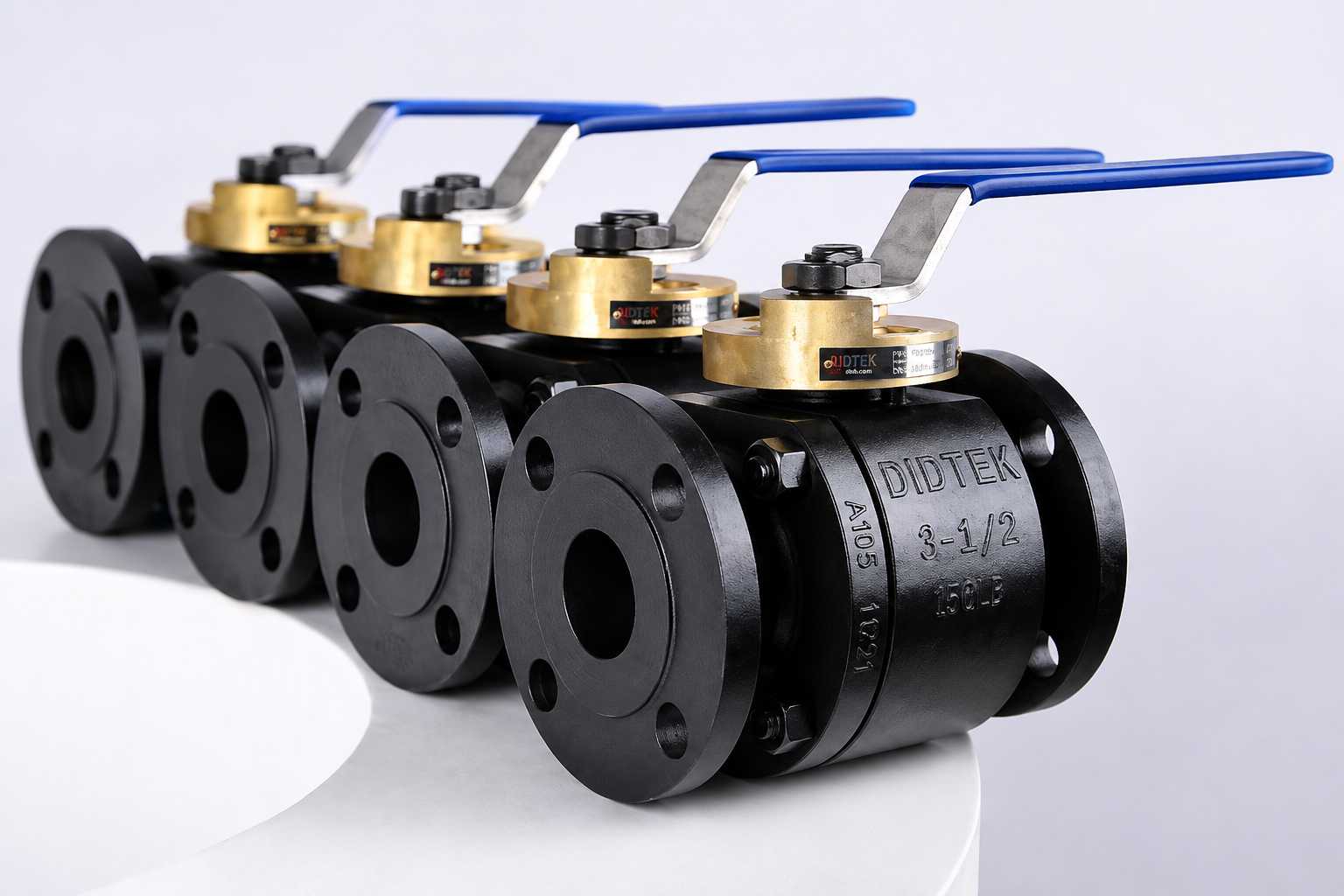
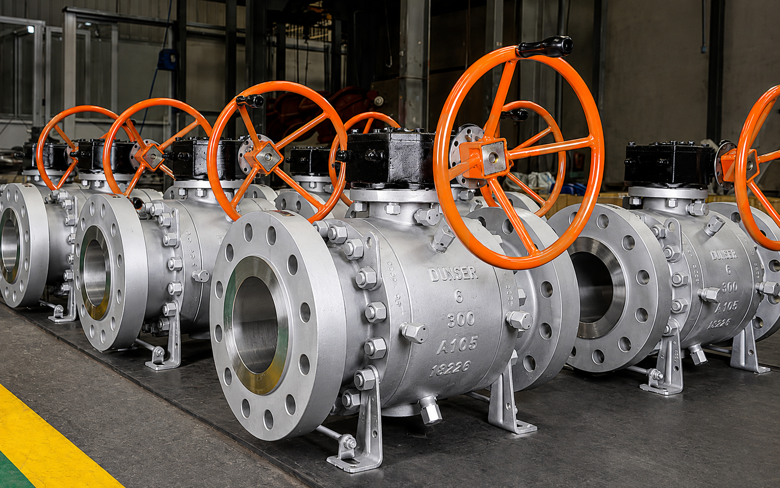
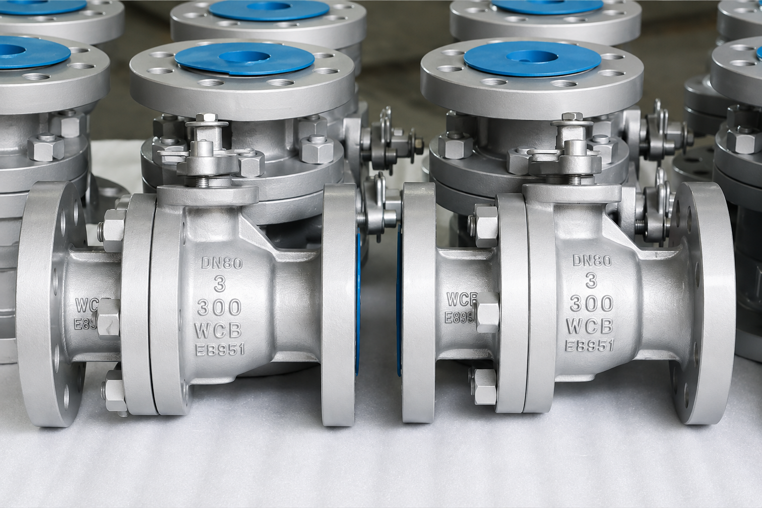
Ball Valve
Valve Configuration: Floating and trunnion-mounted ball valve designs for different pressure and size requirements.
Body Construction: Cast or forged steel body with side-entry, top-entry or fully welded construction.
Bore & Seat: Full-bore or reduced-bore configurations with soft-seated or metal-seated systems.
End & Operation: Flanged or butt-welded ends with manual, gear or actuator operation where specified.
Service Application: Designed for pipeline and process isolation in oil, gas and other pressure-service systems.
A ball valve is manufactured from cast or forged pressure-containing body components with a precision-machined ball, stem, seats and sealing elements, using 90-degree ball rotation to align the through bore with the pipeline for flow or turn it perpendicular to the flow path for shutoff. The body contains line pressure, while the ball-support and seat arrangement control how differential-pressure loads are transferred and sealing contact is maintained. This quarter-turn design provides a direct flow path and short operating stroke, while bore configuration, seat design, ball support and actuator torque determine how the valve is matched to the required service.
The required configuration depends on pressure class, body construction, ball support, full or reduced bore, seat material, end connection, operating temperature, fluid composition and actuator torque. OCTAL STEEL supplies ball valve configurations for pipeline and process applications, including floating ball valves, trunnion ball valves, forged ball valves, cast ball valves, side-entry, top-entry, full-bore, reduced-bore, soft-seated and metal-seated designs. For petroleum and natural-gas pipeline projects, API 6D may be specified; API 608 is another important standard for metal ball valves with flanged, threaded or welding ends.
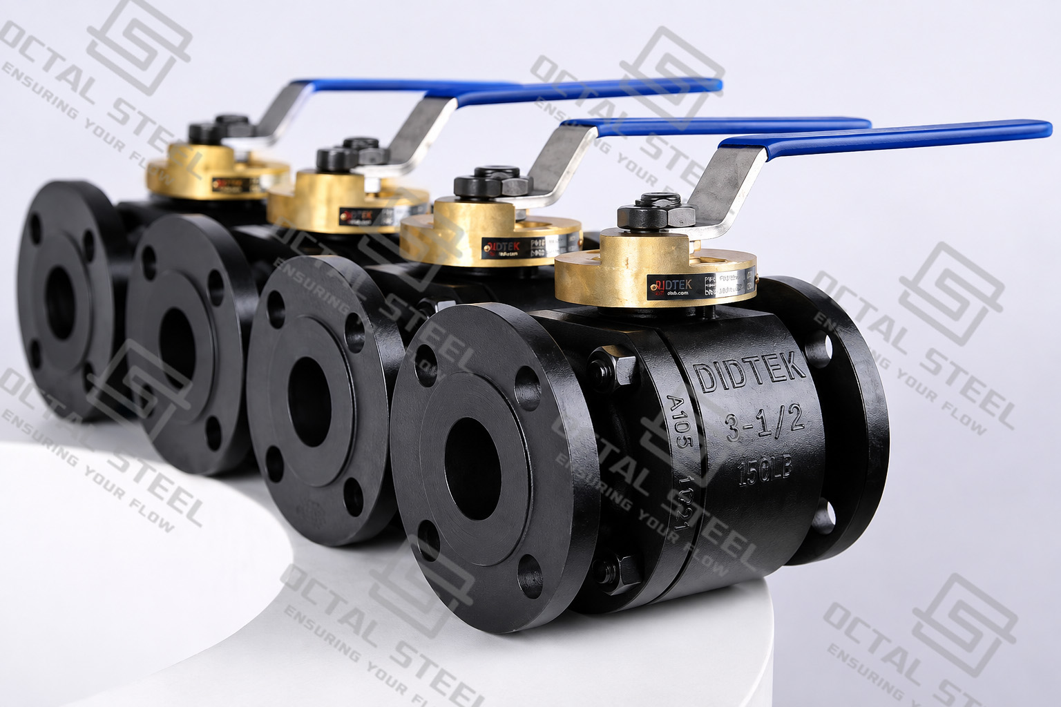
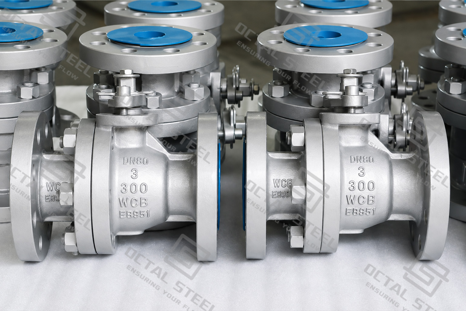
Ball Valve Specifications and Representative Configurations
The table below shows representative configurations rather than a universal size/class matrix. Pressure class, nominal size, body design, bore, material and seat system must be reviewed together before a valve is released for a project.
| Configuration | Representative Range / Design | Engineering Meaning |
|---|---|---|
| Floating Ball Valve | 1-piece and 2-piece designs; representative OCTAL range extends from NPS 1/2 upward depending on construction | Simple ball support for smaller and moderate-size isolation duties |
| 2-Piece Trunnion Ball Valve | NPS 2–16; Class 150–1500 | Fixed-ball arrangement for higher pressure loading and lower operating torque |
| 3-Piece Trunnion Ball Valve | NPS 2–48; Class 150–2500 | Wider size and pressure-class range for pipeline isolation duties |
| Top Entry Ball Valve | Representative range to NPS 48 depending on configuration | Internal components can be accessed from above for suitable in-line maintenance arrangements |
| Full Bore Ball Valve | Bore selected to match the required flow passage | Used where low flow restriction, cleaning access or pig passage is important |
| Reduced Bore Ball Valve | Bore smaller than the connected pipeline flow area | Reduces valve size and mass where a smaller internal flow passage is acceptable |
| Soft Seated Ball Valve | PTFE or other engineered polymer seat systems according to service | Selected for tight shutoff within a compatible pressure-temperature and media range |
| Metal Seated Ball Valve | Metal-to-metal seating system | Used where temperature, solids or severe operating conditions exceed the practical range of soft seats |
| End Connections | Flanged or butt-welded; other end connections for applicable smaller designs | Must match pipeline pressure class, connection standard and installation method |
| Operation | Manual, gear, pneumatic, electric or hydraulic | Actuator selection depends on required valve torque, operating frequency and shutdown philosophy |
The current OCTAL STEEL API 6D page lists floating, trunnion-mounted, top-entry and metal-seated ball valve configurations, while the supplied project brochure further shows cast side-entry, forged side-entry, fully welded and DBB ball valve families. The dedicated trunnion catalogue covers cast and forged, soft-seated and metal-seated configurations and presents full-bore and reduced-bore dimensional series.
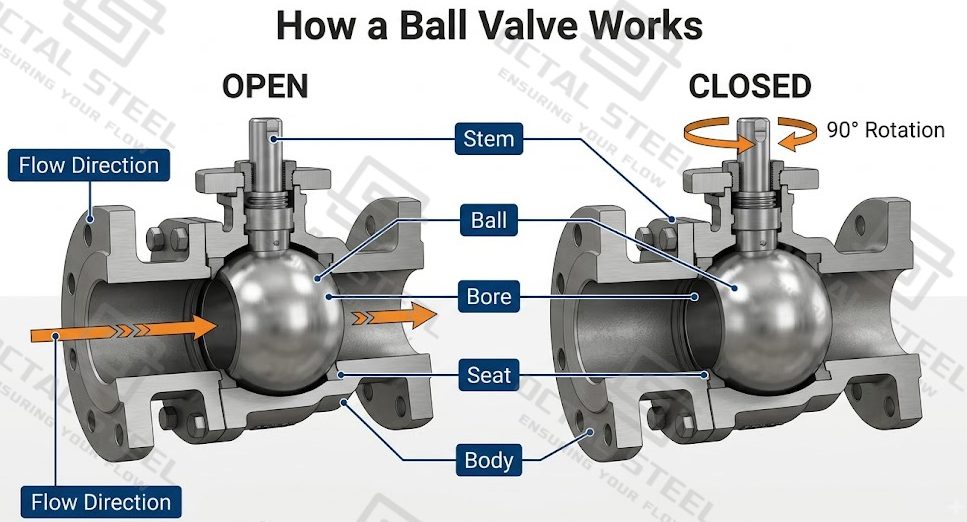
How a Ball Valve Works
A ball valve controls flow by transferring torque from the lever, gearbox or actuator through the stem to a bored spherical ball, which rotates 90 degrees between the open and closed positions.
1. Open Position
The ball bore aligns with the pipeline, creating a direct flow passage through the valve.
2. Quarter-Turn Operation
The stem rotates the ball through 90 degrees, moving the bore away from the pipeline flow path.
3. Closed and Sealing Position
The solid ball surface faces the flow passage and seals against the seat rings. Line pressure then acts on the ball and seats; how this load is supported differs between floating ball valves and trunnion ball valves.
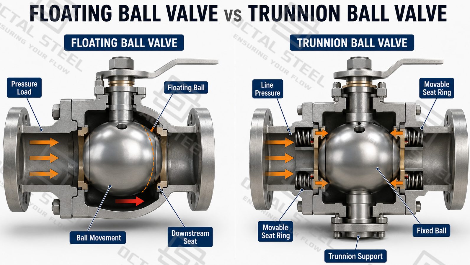
Floating Ball Valve and Trunnion Ball Valve
Floating Ball Valve
A floating ball valve uses a ball connected to the stem but not mechanically fixed by trunnion supports. When the valve closes, line pressure moves the ball slightly toward the downstream seat, increasing ball-to-seat contact and creating the shutoff seal.
This relatively compact arrangement is commonly used for smaller and moderate-size valves where pressure-induced seat loading and operating torque remain manageable. Floating ball valves can be supplied in cast or forged construction, with soft or metal seats and full-bore or reduced-bore configurations depending on the required service.
Trunnion Ball Valve
A trunnion ball valve, also called a trunnion mounted ball valve, mechanically supports the ball around its rotational axis. The ball rotates between open and closed positions but remains substantially fixed, while spring-loaded seat rings move toward the ball and use line pressure to maintain sealing contact.
Because the trunnion supports carry the main pressure load acting on the ball, the design reduces ball-to-seat loading and operating torque as valve size and differential pressure increase. It is therefore commonly selected for larger-diameter and higher-pressure pipeline isolation service.
Floating Ball Valve vs Trunnion Ball Valve
The key difference is which component moves to create the pressure-assisted seal.
| Design Factor | Floating Ball Valve | Trunnion Ball Valve |
|---|---|---|
| Ball Support | Ball is not fixed by trunnions | Ball is mechanically supported |
| Sealing Action | Ball moves slightly toward the downstream seat | Seat rings move toward the fixed ball |
| Pressure Load | Increasing pressure increases ball-to-seat loading | Main ball load is carried by the support system |
| Operating Torque | Increases more noticeably with valve size and differential pressure | Better controlled for larger sizes and high differential pressure |
| Typical Selection | Smaller and moderate-size isolation service | Large-diameter and higher-pressure pipeline service |
The selection is therefore not based only on nominal size. Differential pressure, pressure class, operating torque, seat design and actuator requirements must be evaluated together.
Functions Available with Trunnion Ball Valves
Depending on the specified seat and body configuration, a trunnion ball valve can incorporate additional pipeline isolation functions.
Double block and bleed (DBB) allows the upstream and downstream seats to isolate the body cavity so that trapped fluid can be vented or drained for isolation verification.
Body-cavity pressure relief controls pressure that can develop when trapped fluid inside a closed valve expands because of temperature change. An applicable self-relieving seat arrangement allows excessive cavity pressure to discharge toward the lower-pressure side.
Other available configurations may include blowout-resistant stem design, anti-static continuity, emergency sealant injection, vent and drain connections, and extended stems for buried or remote operation. These features are project-specific and should be stated individually in the valve specification or RFQ.
Ball Valve Types by Engineering Design
A ball valve can belong to several classifications at the same time. For example, one valve may be a forged, side-entry, trunnion-mounted, full-bore, soft-seated ball valve. Treating each of those terms as unrelated “valve types” can make selection confusing. A clearer method is to classify the valve by the design variable being changed. IQS and Wikipedia similarly separate body construction, ball support and bore geometry rather than treating them as one dimension.
| Classification Basis | Main Options | What Changes |
|---|---|---|
| Ball Support | Floating / Trunnion | Pressure load path, seat loading and operating torque |
| Body Construction | Side Entry / Top Entry / Fully Welded | Assembly method, body joints and maintenance access |
| Manufacturing Route | Cast / Forged | Pressure-containing body material route and available geometry |
| Bore | Full Bore / Reduced Bore | Flow area, pressure loss, valve size and pigging capability |
| Seat | Soft Seated / Metal Seated | Sealing mechanism and service-temperature/media capability |
| Operation | Lever / Gear / Pneumatic / Electric / Hydraulic | Operating speed, remote control and required output torque |
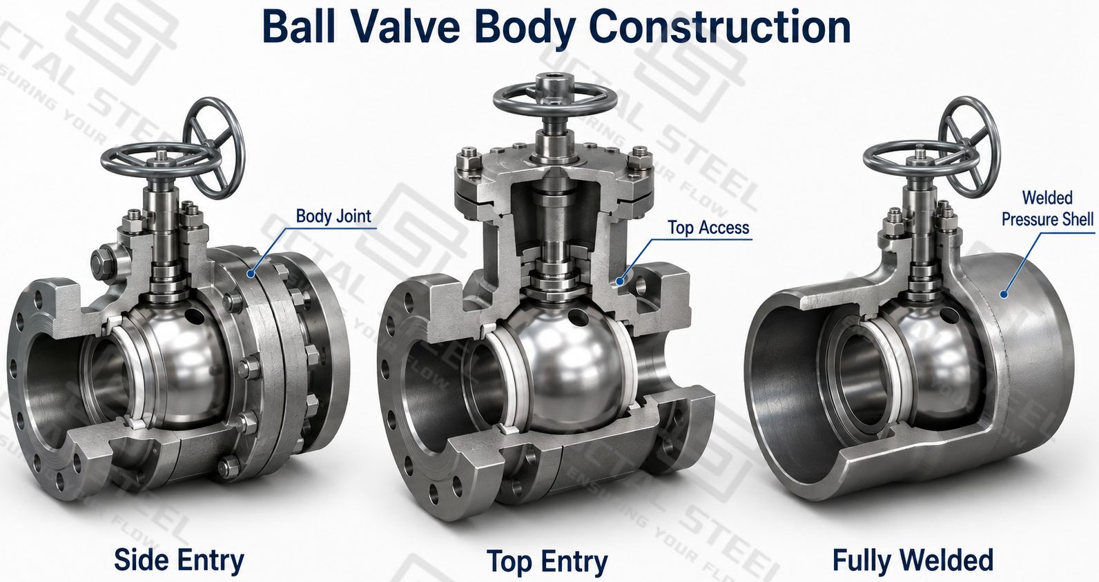
Side Entry, Top Entry and Fully Welded Ball Valves
A side-entry ball valve uses body sections assembled around the ball and seats. This construction is common in both floating and trunnion designs and can be manufactured from cast or forged materials.
A top-entry ball valve provides access to internal components through the upper body opening. Its engineering value is not simply a different external shape; the configuration may simplify suitable in-line inspection and maintenance because internal components can be approached from the top without using the same disassembly sequence as a conventional split-body valve. IQS also identifies maintenance access as the main distinguishing feature of top-entry construction.
A fully welded ball valve eliminates bolted body joints in the principal pressure shell. It is commonly considered when buried or pipeline service makes external body-joint leakage and future access important project considerations. The supplied product brochure includes fully welded ball valves as a separate structural family.
Ball Valve Bore Configuration
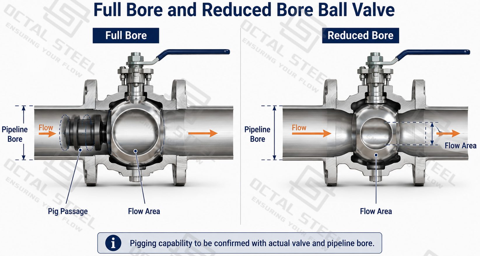
The bore determines the internal flow area through the ball and directly affects flow restriction, pressure loss and pipeline pigging capability. Industrial ball valves are commonly supplied in full bore or reduced bore configurations.
Full Bore Ball Valve
A full bore ball valve uses a ball opening designed to maintain a flow passage close to the connected pipeline bore. The larger internal passage reduces local flow restriction and is particularly important where the pipeline must accommodate pigs or other internal inspection and cleaning tools.
Full bore construction is therefore commonly specified for transmission pipelines, mainline isolation and other services where maintaining pipeline flow area is important.
Reduced Bore Ball Valve
A reduced bore ball valve has an internal ball opening smaller than the connected pipeline bore. The reduced passage creates greater local flow restriction than a comparable full bore design, but it can reduce ball diameter, valve envelope, weight and operating torque.
The bore should be selected according to required flow capacity, allowable pressure loss and pigging requirements rather than nominal valve size alone.
Ball Valve Seat Design
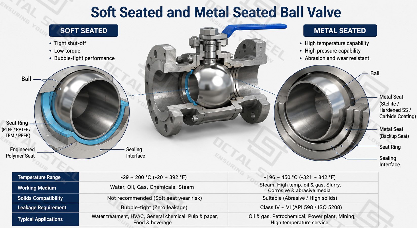
The seat forms the sealing interface between the ball and valve body. Its material and construction influence leakage performance, operating torque and the pressure-temperature range of the complete valve. Ball valves are generally configured with soft seats or metal seats according to the service condition.
Soft Seated Ball Valve
A soft seated ball valve uses an engineered polymer seat, such as PTFE or another specified seat material, to create close contact with the machined ball surface. This arrangement provides effective shutoff where the selected seat material is compatible with the operating pressure, temperature and process medium.
Different polymer materials have different temperature, chemical-resistance and mechanical limits, so the term “soft seated” alone is not sufficient for valve selection.
Metal Seated Ball Valve
A metal seated ball valve uses metallic ball-to-seat sealing surfaces and is considered where high temperature, abrasive solids or other severe operating conditions exceed the practical limits of the selected soft-seat material.
Metal seating changes more than temperature capability. Ball surface condition, seat geometry, material pairing, leakage requirement and operating torque must all be considered as part of the complete valve design.
Seat selection should therefore be based on the actual process medium, temperature, pressure, solids content and required shutoff performance rather than treating metal seating as automatically superior to soft seating.
Ball Valve Materials
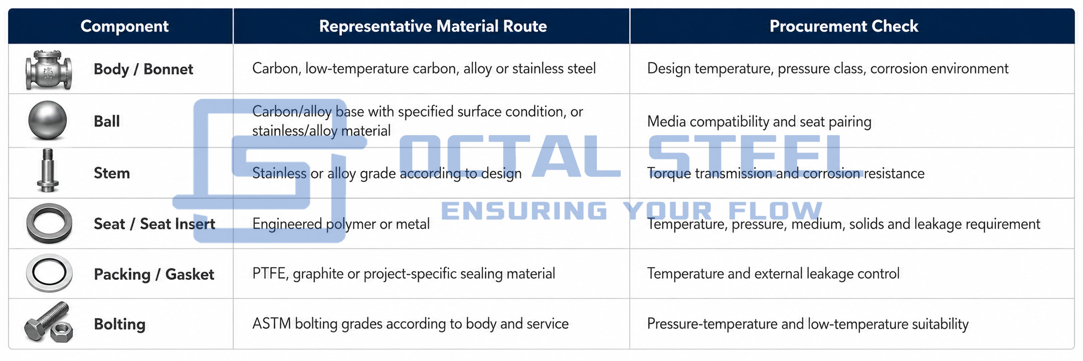
Ball valve material selection covers the complete pressure boundary and sealing system, not only the body grade. The body and bonnet must carry line pressure and external piping loads, while the ball, stem, seat rings, packing and bolting must remain compatible with the operating temperature, fluid composition, pressure differential and required shutoff performance.
For industrial ball valves, the material combination therefore needs to be selected as a system. Carbon steel, low-temperature carbon steel, alloy steel and stainless steel may be used for pressure-containing components depending on service conditions. The ball and stem require suitable strength, corrosion resistance and surface condition, while the seat and packing materials determine sealing behavior under temperature, pressure, cycling and media exposure.
Representative material routes are shown below. Final materials should be confirmed against the specified valve design, pressure class, seat arrangement, service medium and project material specification.
Material Selection Should Follow the Service Condition
The most important control is the compatibility between body material, trim, seat and sealing materials. A suitable body grade alone does not guarantee a suitable valve configuration.
For example:
- Low-temperature service requires attention to the toughness of pressure-containing parts and bolting, not simply a change in body material.
- Corrosive media may require upgraded wetted trim or stainless/alloy components even when the external pressure boundary uses another material route.
- High-temperature or solids-containing service can change the practical seat-material selection and may move the design from a soft-seat arrangement toward a specified metal-seat system.
- High differential pressure increases the importance of ball/seat load, stem torque capacity and the compatibility of contacting surfaces.
- Fire-safe or fugitive-emission requirements, where specified, also affect packing, gasket and secondary sealing arrangements.
For procurement, the material schedule should therefore identify the body, bonnet, ball, stem, seat system, packing, gasket and bolting separately, together with the applicable material specification and inspection/documentation requirements. This avoids treating “ball valve material” as one single grade and reduces the risk of receiving a valve with an acceptable body material but unsuitable trim or sealing components.
API 6D Ball Valve and Applicable Standards
The standard must be specified according to the actual valve duty rather than added as a marketing label.
API Specification 6D covers requirements for valves used in petroleum and natural-gas pipeline and piping applications. API currently lists the 25th Edition with Addendum 3 issued in 2025. Its scope includes design, manufacturing, materials, quality control, assembly, testing, marking and documentation requirements for ball and other pipeline valve types.
API 608, currently in its 7th Edition, addresses metal ball valves with flanged, threaded and welding ends.
ASME B16.34-2025 covers pressure-temperature ratings, materials, dimensions, examination, testing and marking requirements for applicable flanged, threaded and welding-end valves. ASME B16.5 and B16.47 address flange interfaces within their respective size ranges, while ASME B16.10 addresses face-to-face and end-to-end valve dimensions.
A project specification may require additional testing, fire-safe qualification, fugitive-emission requirements, sour-service material controls or other purchaser-specific criteria. Such requirements must be confirmed on the purchase order rather than assumed from the valve type alone.
How to Select a Ball Valve for a Project
Ball valve selection is most reliable when the configuration is built in a fixed engineering sequence:
Required line function → nominal size → design pressure/class → operating temperature → medium → floating or trunnion support → full or reduced bore → body construction → body and trim materials → soft or metal seat → end connection → actuator → testing and documentation.
For a smaller general isolation line, a floating design may provide the required shutoff without the added complexity of a trunnion system. For a large-diameter or high-pressure pipeline, a trunnion mounted ball valve becomes more attractive because the fixed ball arrangement controls pressure loading and operating torque differently. Where pigging is required, full bore becomes a major selection condition. Where service temperature or solids exceed the practical capability of the selected polymer seat, a metal-seated configuration must be evaluated.
Actuator selection comes after the valve configuration because torque demand changes with valve size, differential pressure, seat design and operating condition. Selecting an actuator before confirming the actual valve torque can lead to an incorrectly sized operating system.
Download:Ball Valve Design Configuration and Selection Guide.pdf
Manufacturing and Quality Control
Industrial ball valve production begins with identification of the pressure-containing body and trim materials. Cast or forged body components are machined to establish the body cavity, end connections and sealing interfaces. The ball is machined to the required bore and spherical sealing surface; stem, seat support and connection components are then machined before the seat and sealing system is assembled.
Quality control should therefore follow the same load path as the valve itself: material identity, body condition, critical dimensions, ball and seat surfaces, stem and anti-blowout arrangement, end connection, assembled operation, pressure-containing integrity and seat sealing performance.
For a trunnion valve, additional inspection attention is required at the ball supports, seat rings, body-cavity connections, injection or vent/drain interfaces where provided, and actuator mounting arrangement. The supplied Trunnion Ball Valve catalogue illustrates these components separately in its exploded views and material schedules.
Ball Valve Applications
Transmission pipeline isolation. Large-diameter pipeline block valves must control line pressure while remaining operable under differential pressure. Trunnion support, full-bore flow path, actuator torque, body-cavity management and end connection become key configuration inputs.
Pig launcher, receiver and mainline sections. The required internal passage must be checked against pig dimensions and pipeline bore. A nominal valve size alone does not prove that the valve provides the required unobstructed flow path; full-bore configuration must be confirmed.
Refinery and petrochemical unit isolation. Fluid composition, temperature, pressure class, shutdown philosophy and seat compatibility determine whether soft-seated or metal-seated construction is appropriate.
Pump, compressor and remotely operated stations. Valve torque and operating frequency affect the selection of gearbox, pneumatic, hydraulic or electric actuation. The actuator must be matched to the selected valve rather than specified independently.
Download:Trunnion_Ball_Valve_Isolation_Safety_and_Inspection_Guide.pdf
OCTAL STEEL Ball Valve Supply and Project Support
OCTAL STEEL supplies ball valves for pipeline, oil and gas, petrochemical and industrial piping projects, covering floating and trunnion ball valves in cast, forged, side-entry, top-entry and fully welded constructions. Representative supply ranges extend from NPS 1/2–8 for floating ball valves and up to NPS 60 for applicable side-entry and fully welded designs, with pressure classes available up to Class 2500 depending on valve construction and size. DBB ball valve configurations are also available for applicable pipeline isolation requirements.
The valve configuration can be matched to project conditions with full-bore or reduced-bore flow paths, soft or metal seats, carbon steel, alloy steel or stainless steel pressure-containing materials, flanged or butt-welded ends, and manual, gear, pneumatic, electric or hydraulic operation. Trunnion-mounted designs can also incorporate functions such as double block and bleed, cavity pressure relief, vent and drain connections, emergency sealing provisions and stem extensions where specified.
Beyond supplying the valve itself, OCTAL STEEL can support project configuration around size, pressure class, bore, materials, seat system, end connection and actuator requirements, together with the specified inspection and documentation scope. This allows the ball valve to be selected as a complete pipeline isolation assembly rather than as a nominal size and pressure rating alone.
FAQ
Q: When is a trunnion ball valve preferred over a floating ball valve?
A: Trunnion construction is commonly selected as diameter, pressure loading and operating torque increase. The ball is mechanically supported while movable seat rings provide the sealing load, reducing the direct pressure force that would otherwise push a floating ball against the downstream seat.
Q: Does Class 2500 mean every ball valve size is available at Class 2500?
A: No. Pressure class is not independent of nominal size, body construction, material, bore and seat design. The supplied trunnion dimensional tables show that available size ranges change with pressure class, so the exact size/class matrix must be confirmed for the selected configuration.
Q: What information is required to order an API 6D ball valve?
A: Specify the valve type, size, class, bore, body and trim materials, seat system, end connection, actuator, process medium, design conditions and required inspection/documentation. API 6D should be stated as the applicable project standard where required.
Q: Is a full bore ball valve always the better choice?
A: No. Full bore is important when unrestricted flow, low local pressure loss or pig passage is required. A reduced bore may provide a smaller and lighter valve where the reduced flow area is acceptable. The correct choice depends on the pipeline operating requirement rather than nominal size alone.