Your Responsible Supplier Partner for Oil and Gas Products.

X95 Drill Pipe
Recent Products

Rencent Articles





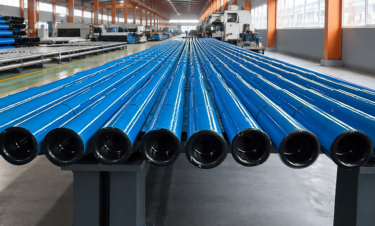
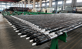
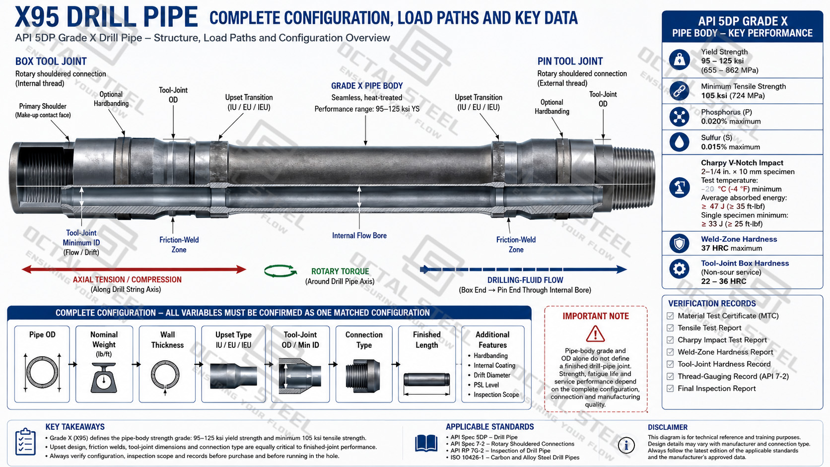
X95 drill pipe is an API 5DP Grade X drill-string tubular used to transmit torque, carry axial load and circulate drilling fluid in rotary drilling operations. It is manufactured from a seamless, heat-treated pipe body with upset ends and friction-welded pin and box tool joints. The Grade X pipe body has a specified yield-strength range of 95–125 ksi (655–862 MPa) and a minimum tensile strength of 105 ksi (724 MPa), placing it between E75 and G105 for drilling programs that require more pipe-body strength than E75 without automatically moving to a higher grade. Final operating capacity still depends on pipe size, remaining wall thickness, tool-joint dimensions and connection design.
X95 Drill Pipe Standards
| Standard | Application to X95 Drill Pipe |
|---|---|
| API Spec 5DP, 2nd Edition, including current addenda and errata | Pipe-body manufacture, tool joints, friction welding, dimensions, material requirements, testing, marking and technical delivery |
| ISO 11961:2018 with Amendment 1:2020 | International technical delivery conditions and PSL-1, PSL-2 and PSL-3 requirements |
| API Spec 7-2 / ISO 10424-2 | Threading and gauging of rotary shouldered pin and box connections |
| API RP 7G | Drill-stem design calculations, performance properties and operating limits |
| API RP 7G-2 / ISO 10407-2 | Inspection and classification of used drill-stem components |
| ISO 15156 / NACE MR0175, when specified | Material review for equipment exposed to H2S-containing fluids |
API Spec 7-2 controls the rotary shouldered connection rather than the pipe-body grade. Its current Second Edition includes Addendum 3, issued in September 2025. Consequently, specifying “X95” alone does not define the connection, tool-joint OD, pin ID, shoulder geometry or gauge requirements.
Download :API Spec 5DP Drill Pipe Data Reference
X95 Drill Pipe Specifications
| Specification Item | Available Range or Requirement |
|---|---|
| Product Standard | API Spec 5DP; ISO 11961 |
| Pipe-Body Grade | API Grade X, commonly identified as X95 |
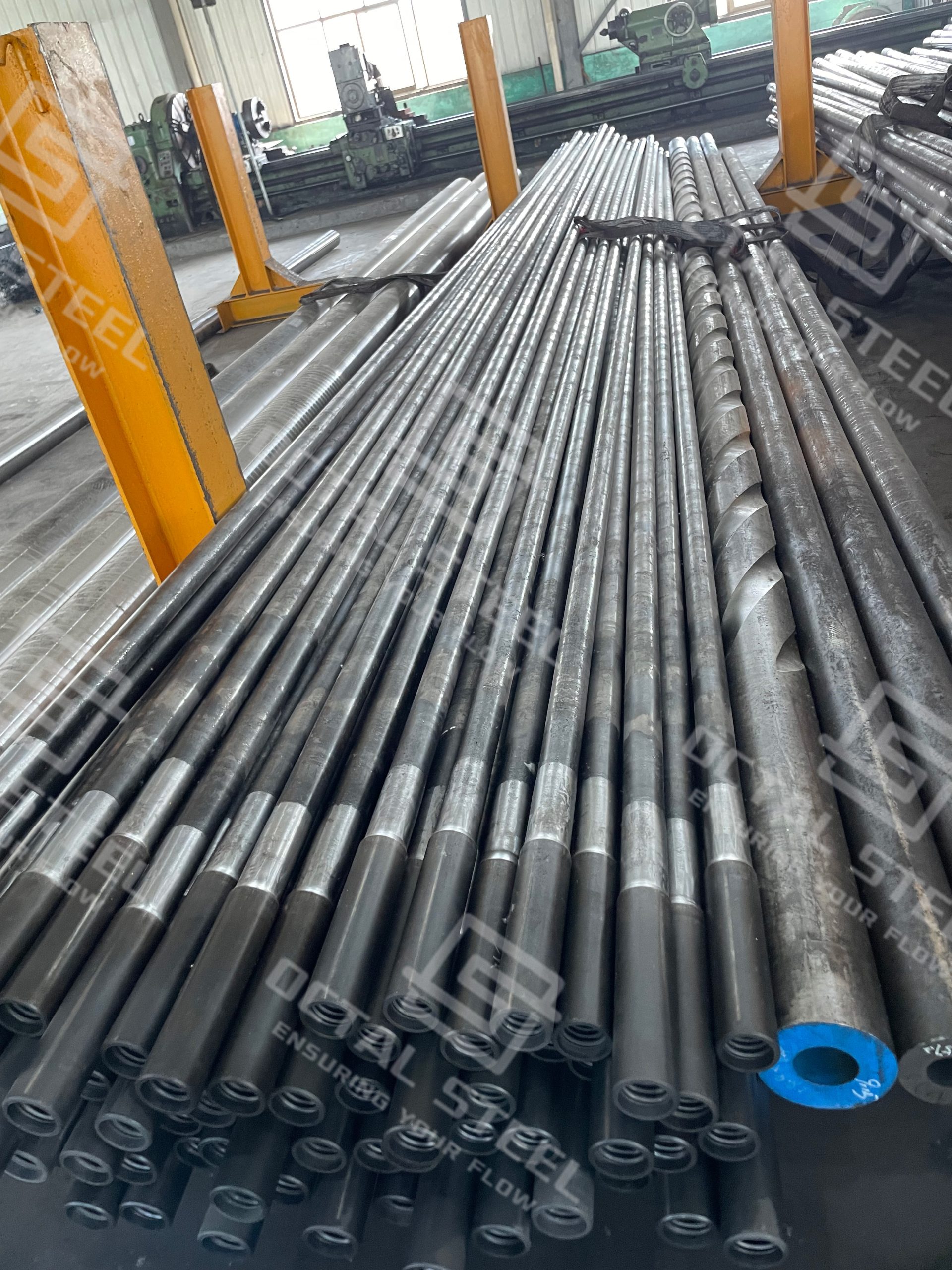
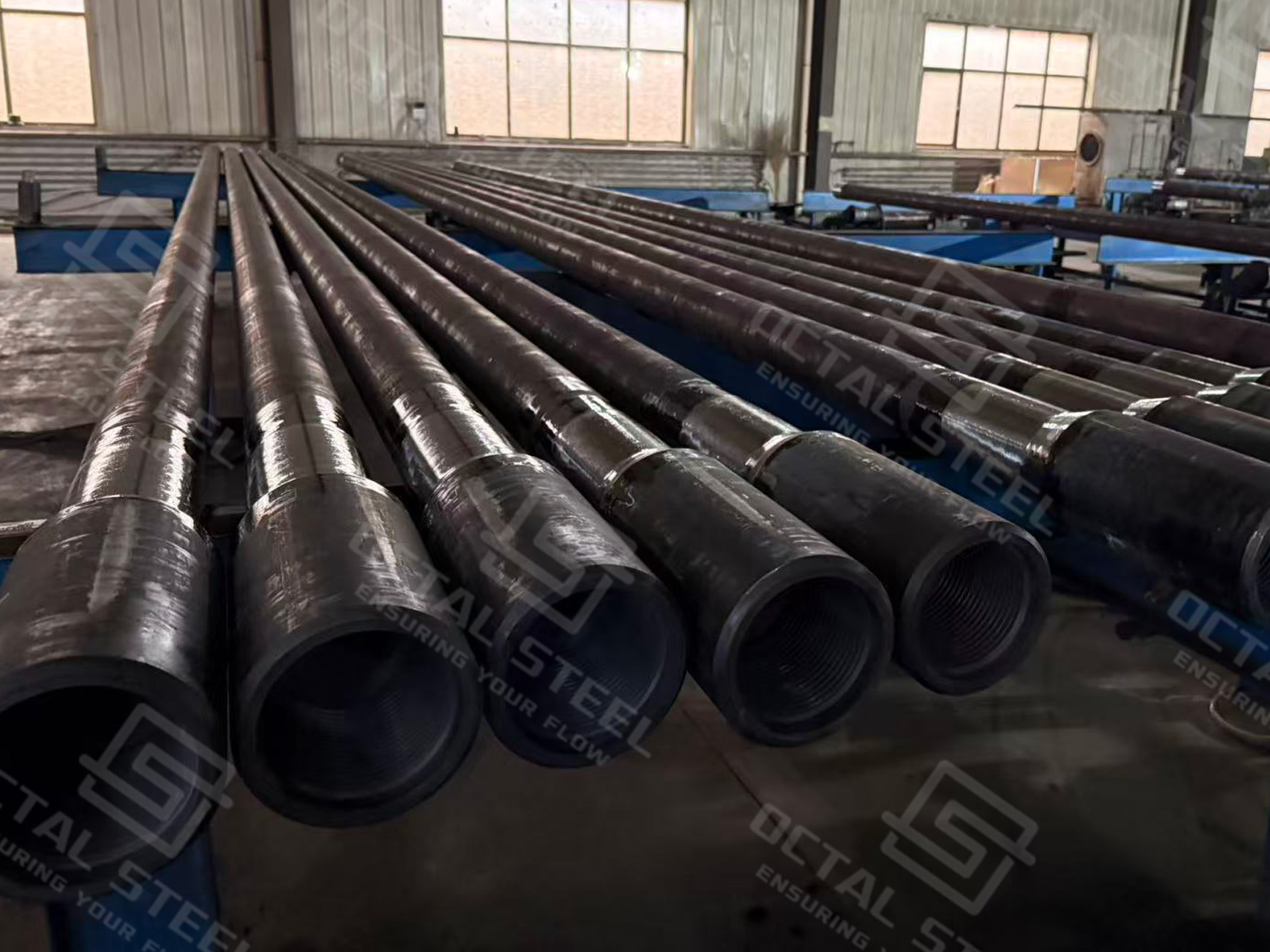
| Construction | Seamless heat-treated pipe body with upset ends and friction-welded pin and box tool joints |
| Pipe-Body OD | 2-3/8 to 6-5/8 in. / 60.3 to 168.3 mm, subject to the confirmed body configuration |
| Nominal Weight | Selected according to pipe OD, wall thickness and API 5DP configuration |
| Upset Type | IU, EU or IEU, depending on the selected pipe and tool-joint design |
| Tool Joint | Weld-on pin and box; OD, minimum ID, tong space and length confirmed by the approved data sheet |
| Connection Options | NC, FH, IF, REG or project-specified rotary shouldered connection |
| Length Range | R1: 18–22 ft; R2: 27–30 ft; R3: 38–45 ft |
| Product Specification Level | PSL-1, PSL-2 or PSL-3 as stated in the purchase specification |
| Optional Features | Tool-joint hardbanding, internal coating, thread protectors and project-specific marking |
| Inspection Documents | MTC, mechanical-test report, dimensional report, weld-zone NDT, thread-gauging record and packing-list traceability |
The ranges above describe the available specification variables rather than fixed size-and-connection combinations. Pipe-body OD, nominal weight, upset type, tool-joint OD/ID and connection are selected as a matched configuration because each affects tensile section, hydraulic clearance, torsional capacity and compatibility with the existing drill string. Final dimensions and tolerances should follow the approved product data sheet and purchase specification.
X95 Drill Pipe Mechanical Properties
| Property | API 5DP Grade X Requirement | Verification |
|---|---|---|
| Minimum Yield Strength | 95 ksi / 655 MPa | Tensile report linked to pipe-body heat and heat-treatment lot |
| Maximum Yield Strength | 125 ksi / 862 MPa | Result remains within the Grade X acceptance range |
| Minimum Tensile Strength | 105 ksi / 724 MPa | Verified from the identified tensile specimen |
| Minimum Elongation | Calculated from specimen area under API 5DP | Reported with specimen dimensions |
| Pipe-Body Phosphorus | 0.020% maximum | Heat analysis reported on the MTC |
| Pipe-Body Sulfur | 0.015% maximum | Heat analysis reported on the MTC |
| PSL-1 Pipe-Body CVN, 10 × 10 mm Specimen | 54 J minimum average; 47 J minimum individual at 21 ± 3°C | Charpy report identifies specimen size and test temperature |
| Weld-Zone Hardness | 37 HRC maximum for surface value and mean through-wall value | Weld-lot hardness report |
| Non-SS Tool-Joint Box Hardness | 285–341 HBW | Tool-joint heat-treatment and hardness record |
Grade X pipe-body acceptance includes a yield-strength range of 95–125 ksi (655–862 MPa), minimum tensile strength of 105 ksi (724 MPa), phosphorus of 0.020% maximum and sulfur of 0.015% maximum. For PSL-1, a full-size 10 × 10 mm longitudinal Charpy specimen tested at 21 ± 3°C requires at least 54 J average and 47 J for any individual specimen; the corresponding limits are 43/38 J for 10 × 7.5 mm specimens and 30/26 J for 10 × 5 mm specimens.
The friction-weld zone is limited to 37 HRC maximum for both surface hardness and mean through-wall hardness. For non-sour-service tool joints, the box hardness range is 285–341 HBW. Under PSL-1, Grade X pipe-body tensile and Charpy testing is performed at least once per 200 pieces or production lot for sizes below 6-5/8 in., and once per 100 pieces or lot for 6-5/8 in. and larger; surface hardness is checked on every weld at three positions spaced 120° apart.
These figures qualify the production material and weld lot, not the allowable load of the finished joint. Actual tensile and torque capacity still depends on pipe OD, wall thickness, remaining section, tool-joint OD/ID, connection geometry and combined loading. The release documents should therefore identify the pipe-body heat, tensile and Charpy results, weld-zone hardness and tool-joint hardness for the delivered production lots.
X95 Drill Pipe Size and Configuration Selection
X95 drill pipe size should be selected as a complete pipe-body and tool-joint configuration. Pipe OD and nominal weight determine the wall thickness, internal diameter and pipe-body cross-sectional area, while the tool-joint OD, minimum ID and connection affect annular clearance, hydraulic passage and torsional capacity.
For example, an existing string may use 5 in. X95 drill pipe, 19.5 lb/ft, NC50 connection and R2 length. A replacement joint described only as “5 in. X95 with NC50” may still have a different nominal weight, tool-joint OD, minimum ID or finished length. A smaller tool-joint bore can restrict drift passage and increase pressure loss, while a different OD may affect annular clearance and compatibility with elevators, slips or other handling equipment. The 5 in., 19.5 lb/ft configuration is also used in API drill-stem calculation examples, but the complete connection and tool-joint dimensions still require confirmation.
Replacement orders should therefore be checked against the existing pipe tally, original data sheet or inspection record. The required nominal weight, upset type, tool-joint OD/ID, connection and finished length should all match; the grade name and pipe OD alone are not sufficient.
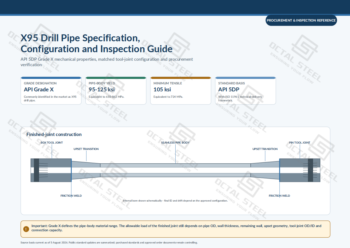
Download:X95 Drill Pipe Specification,Configuration and Inspection Guide
Where X95 Fits in Drill Pipe Grade Selection
X95 should not be assigned to a fixed well depth. Two wells of similar measured depth can impose very different pipe loads because of buoyed string weight, hole inclination, friction, dogleg severity, planned overpull, rotary torque and operating practice.
| Grade | Minimum Pipe-Body Yield Strength | Practical Selection Position |
|---|---|---|
| E75 | 75 ksi / 517 MPa | Lower pipe-body strength where calculated tension and overpull remain within the selected configuration |
| X95 | 95 ksi / 655 MPa | Intermediate strength where E75 provides insufficient margin but G105 is not required by the verified load case |
| G105 | 105 ksi / 724 MPa | Higher pipe-body strength where the selected X95 size cannot provide the required margin |
A move from X95 to G105 increases the specified pipe-body strength, but it does not correct restricted bore clearance, insufficient tool-joint section, incompatible connections, worn shoulders or a fatigue-sensitive upset transition. Grade selection and dimensional selection must therefore remain separate engineering checks.For a detailed review of the strength difference, combined-load behavior and grade-selection boundaries, see our X95 vs G105 drill pipe comparison.
X95 can also be used within a mixed-grade string, provided that connection compatibility, tool-joint dimensions, internal clearance and identification are controlled. Operating limits should be based on the weakest relevant section rather than the highest grade present in the string.
X95 Drill Pipe Applications
Manufacturing and Inspection Control
Production of finished X95 drill pipe normally includes pipe-body manufacture, upsetting, heat treatment, tool-joint manufacture, friction welding, weld-zone heat treatment, flash removal, connection machining and final inspection. Manufacturer process sequences can vary, so release documentation should identify the controls applied to the actual order.
| Control Point | What Is Checked | Release Evidence |
|---|---|---|
| Pipe Body | OD, wall thickness, straightness, heat treatment and Grade X mechanical results | MTC and mechanical-test report |
| Upset Transition | Internal profile, external geometry, alignment and surface condition | Upset dimensional report |
| Tool Joint | Material identity, OD, minimum ID, hardness and connection designation | Tool-joint inspection record |
| Friction Weld | Alignment, flash removal, weld profile, heat treatment, hardness and NDT acceptance | Weld-lot and NDT report |
| Pin and Box | Thread form, taper, lead, shoulder condition, standoff and gauge result | API 7-2 thread-gauging record |
| Optional Hardbanding | Material, position, width, surface condition and cracking acceptance | Hardbanding inspection record |
| Final Joint | Length, drift, marking, protectors, bundle identity and document linkage | Final inspection report and packing list |
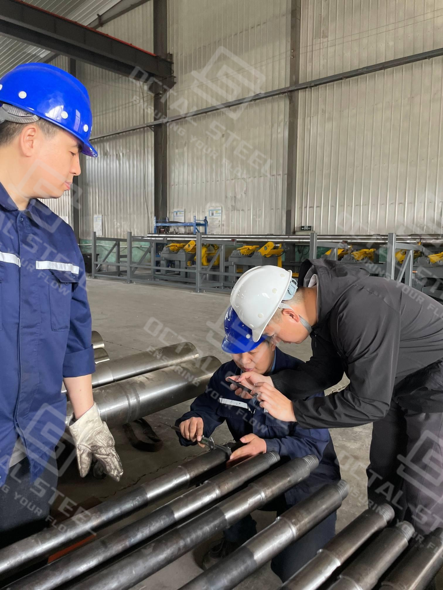
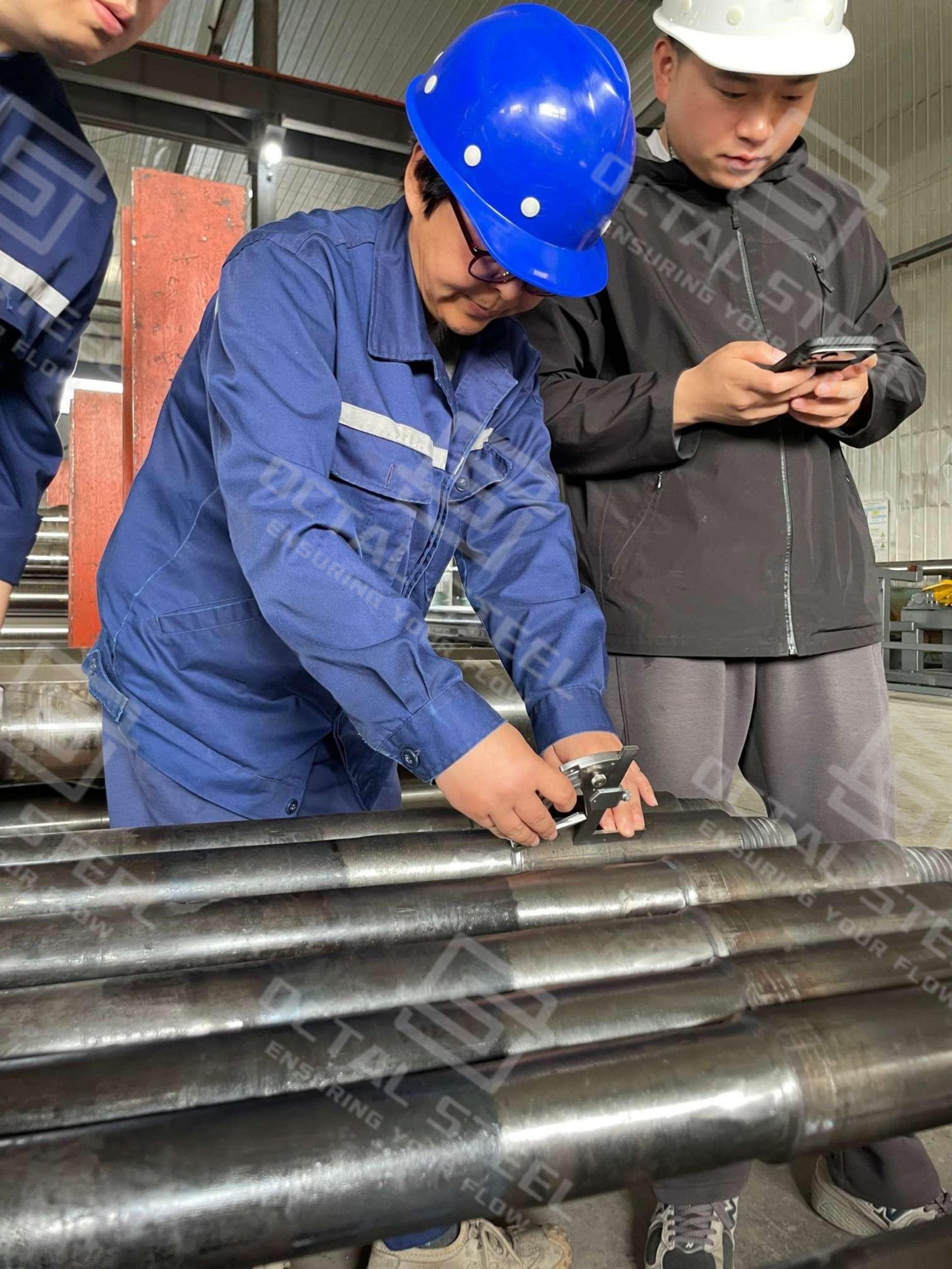
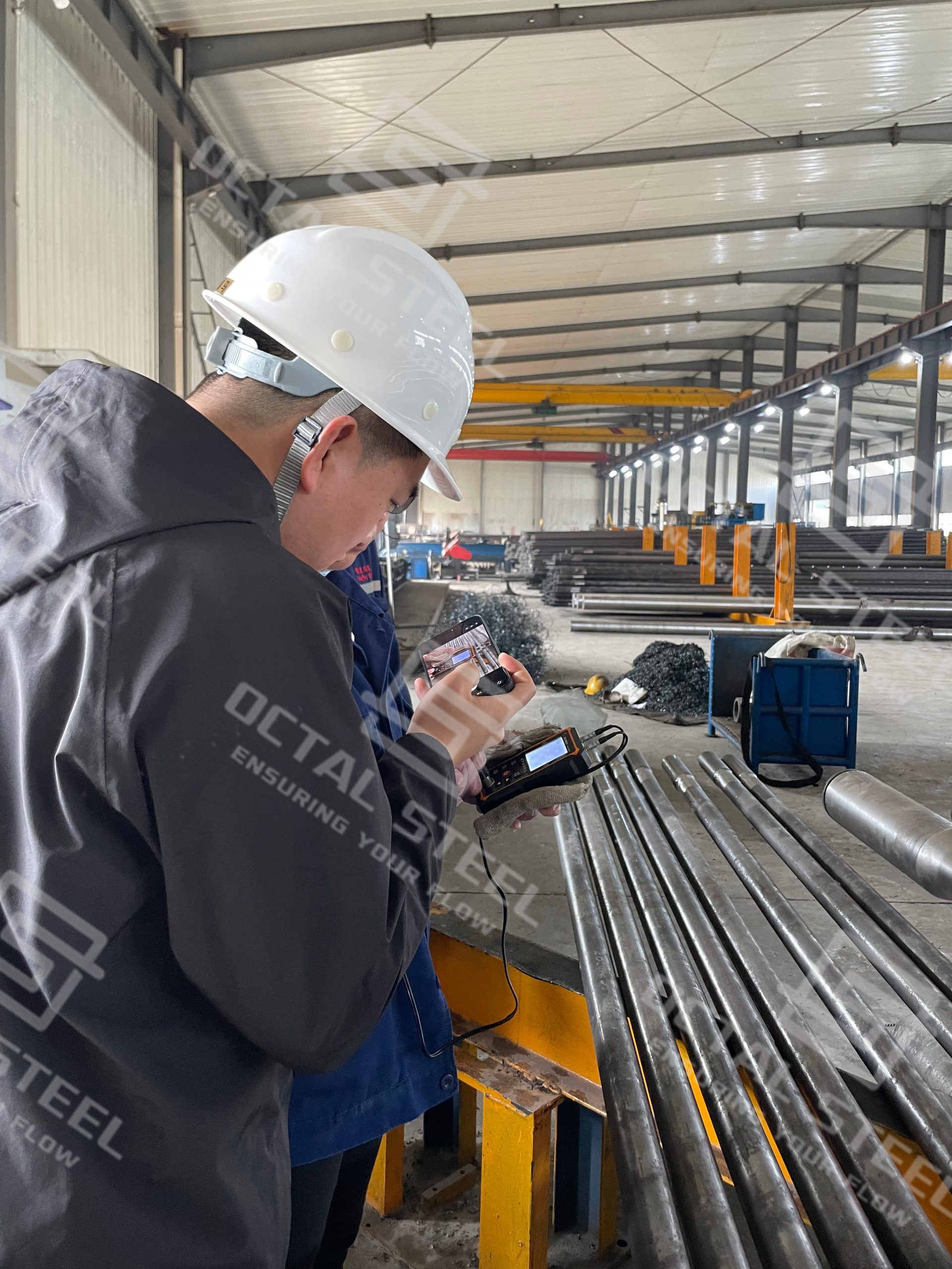
Inspection focuses on the areas most likely to affect service performance. Wall thickness is verified along the pipe body, with additional attention to the body-to-upset transition, where automated inspection coverage may be limited. Grade X tensile and Charpy results are recorded by production lot, while weld-zone hardness is checked around each friction weld before the finished joints are released.
X95 Drill Pipe for H₂S Service
Standard API Grade X95 drill pipe is not automatically qualified for sour service. Where H₂S is present, the purchase specification should define the service conditions and applicable ISO 15156/NACE MR0175 requirements. Material hardness, SSC resistance and any additional testing must be confirmed separately, and a qualified sour-service drill-pipe grade may be required.
Why Choose Octal Drill Pipes
Octal focuses on the details that commonly create problems after delivery. Before production, the pipe OD, nominal weight, upset, tool-joint OD/ID, connection, length, hardbanding and inspection scope are confirmed on one approved data sheet, helping the finished X95 joints match the existing drill string and handling equipment.
Each joint remains traceable to its pipe-body heat, tool-joint material and friction-weld lot. MTCs, mechanical-test results, weld-zone NDT and thread-gauging records are compiled with the shipment, providing a clear basis for receiving inspection, string matching and future maintenance.
FAQ
Q1: Does API 5DP X95 drill pipe automatically carry the API Monogram?
A1: No. Compliance with API 5DP does not automatically mean the product is monogrammed. When the API Monogram is required, the purchase order should state it clearly, and the manufacturer’s active license and product scope should be verified in the API Composite List.
Q2: Can X95 drill pipe from different manufacturers be used in the same string?
A2: It may be possible when the connection, tool-joint OD/ID, shoulder dimensions, drift and make-up requirements are compatible. The X95 grade and pipe OD alone do not establish interchangeability, particularly where the existing tool joints have wear or dimensional differences.
Q3: Is make-up torque determined by the X95 drill pipe grade?
A3: No. X95 defines the pipe-body strength grade, while make-up torque is determined by the rotary-shouldered connection, tool-joint geometry and applicable connection procedure. The specified torque should be confirmed from the approved connection data rather than inferred from the pipe grade.
Q4: How should buyers compare two quotations for the same X95 drill pipe size?
A4: Compare the complete configuration, including nominal weight, wall thickness, upset, tool-joint OD and minimum ID, connection, PSL, hardbanding, internal coating and inspection scope. Two quotations using the same grade and pipe OD may represent materially different finished joints.
Q5: Can used X95 drill pipe be accepted from the original MTC alone?
A5: No. The MTC confirms the original material and production results but does not show current wall loss, fatigue cracking, tool-joint wear or thread condition. Used joints require a current inspection and classification based on measured dimensions and the agreed API RP 7G-2 inspection level.