Your Responsible Supplier Partner for Oil and Gas Products.

How Do Steel Silos Work?
How Do Steel Silos Work?
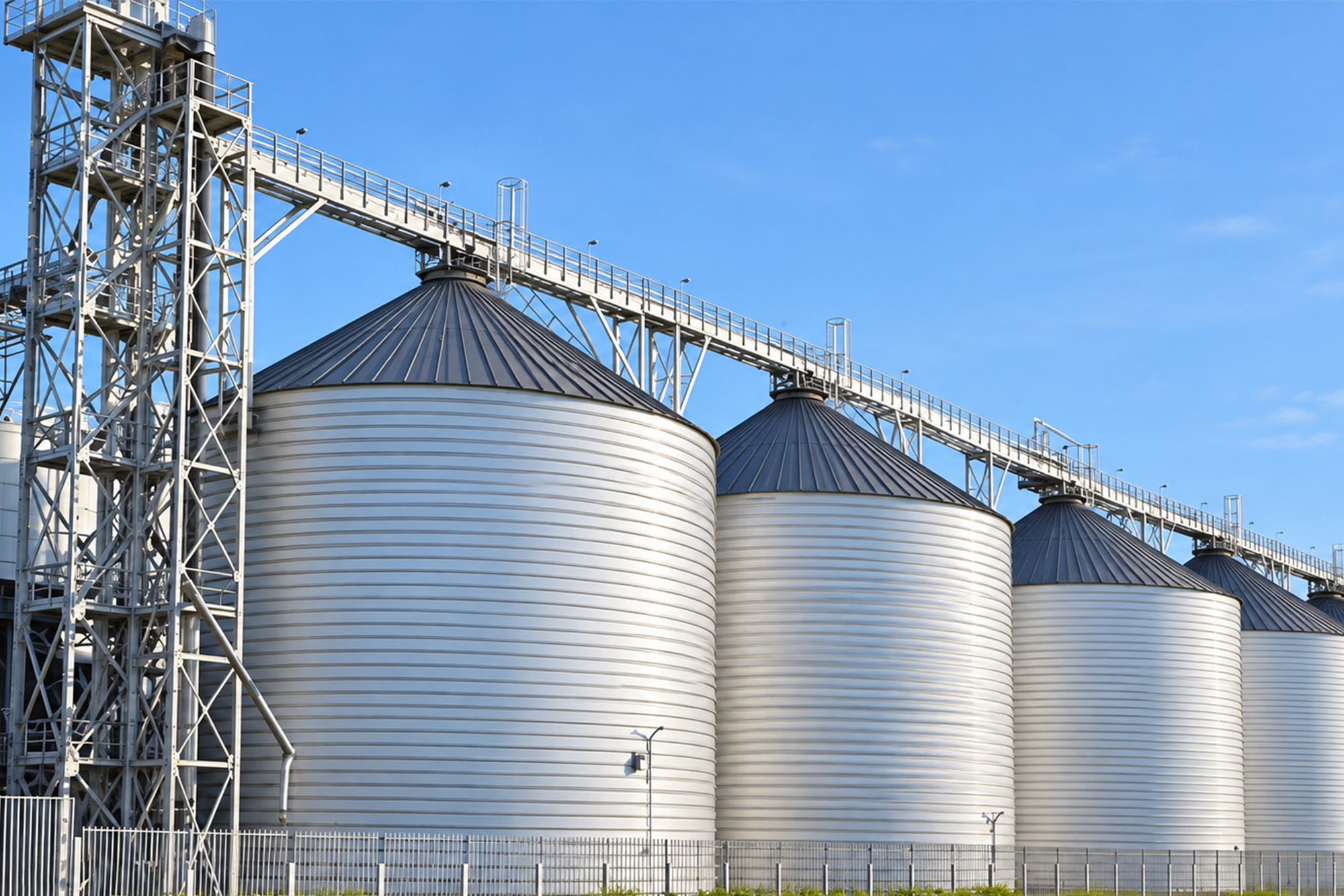
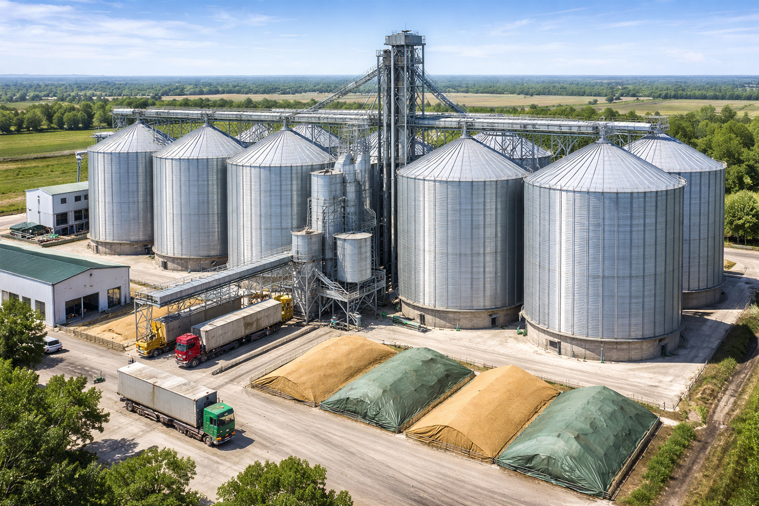
Steel silo operates by separating bulk-material receiving from downstream consumption. Material is conveyed into the upper part of the silo and accumulates under gravity, while the cylindrical shell and bottom structure contain the stored material and carry the resulting loads. When material is required downstream, it moves toward one or more outlets at the lower part of the silo and is transferred to a feeder, conveyor, weighing system, or other process equipment. The complete operating path is therefore filling → accumulation and storage → discharge → downstream transfer.
The way material moves through this sequence depends on its bulk-solid properties. Free-flowing grains can generally move toward an outlet readily under gravity, whereas fine cohesive powders may consolidate during storage, form stable arches above an outlet, or leave stagnant regions during discharge. Pneumatically filled powders also introduce conveying air into the silo, which must be vented and filtered as the solids remain in storage. For this reason, the steel silo working principle is governed not only by storage volume, but by the interaction between the stored material, filling method, silo geometry, outlet, and withdrawal equipment.
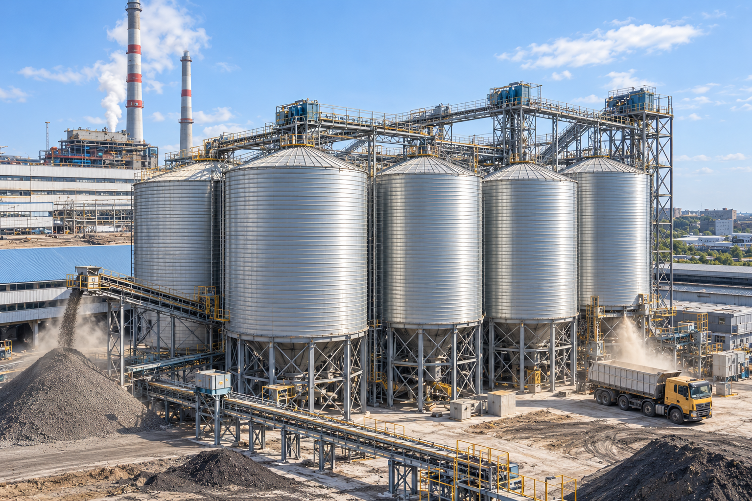
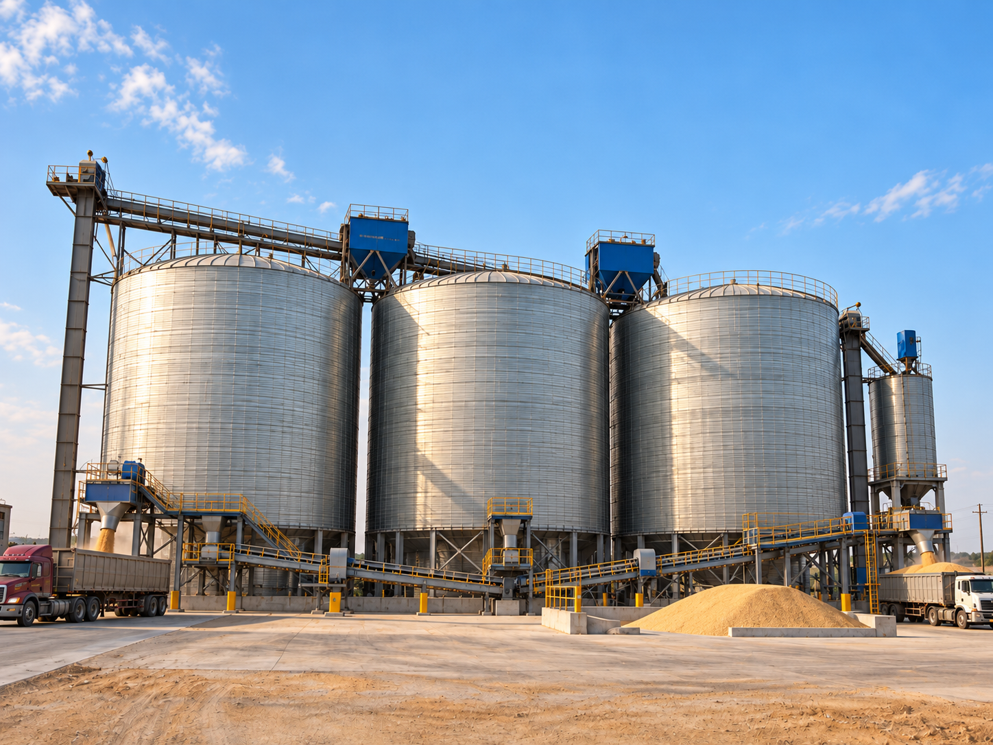
How Does a Steel Silo Operate as a Complete System?
A steel silo operates as part of a bulk material handling system, rather than as an isolated storage vessel. Material must first be received and transferred to the silo, retained within the available storage volume, released through the discharge section, and then delivered to the next conveying or processing stage. Each stage performs a different function within the material path, and the equipment used at these interfaces depends on the stored material and the required operating duty.
| Operating Stage | What Happens in the System | Main Operating Requirement |
|---|---|---|
| Material Receiving | Bulk material arrives from a production line, truck unloading point, or other upstream source. | Receiving capacity must match the incoming material supply. |
| Conveying and Filling | Material is transferred to the silo inlet by mechanical or pneumatic conveying equipment. | The filling method and transfer rate must suit the material being handled. |
| Storage | Material accumulates inside the silo and provides inventory between incoming supply and downstream demand. | Usable capacity and storage conditions must match the required operating buffer. |
| Discharge | Stored material moves toward the outlet by gravity or with appropriate reclaim or flow assistance. | The outlet arrangement must provide stable flow for the stored material. |
| Controlled Feeding | Material leaving the silo is transferred to a conveyor, weighing system, or process equipment. | Feed rate must match downstream consumption rather than simply empty the silo as quickly as possible. |
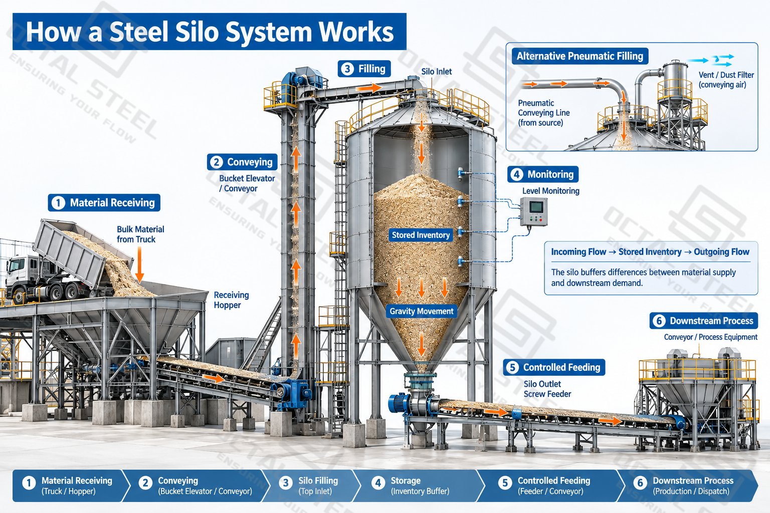
The silo body provides the storage volume, but it does not perform every material-handling function by itself. Conveying equipment brings material to the inlet, the silo contains the accumulated inventory, and the outlet and withdrawal equipment return that material to the process. This operating path provides the framework for understanding what happens during filling, storage, and discharge.
How Does the Filling Process Work in a Steel Silo?
Material normally enters a steel silo through an inlet at the upper section, but the transfer mechanism depends on the physical form of the bulk solid. Granular products can be lifted and conveyed as discrete particles, while fine powders can be transported in an air stream. This difference affects not only the conveying equipment, but also what happens when the material reaches the silo.
| Filling Method | Typical Materials | Material Path | What Happens at the Silo | Main Operating Considerations |
|---|---|---|---|---|
| Mechanical Conveying | Grain, feed pellets, biomass pellets, and other suitable granular materials | Receiving → Bucket elevator / conveyor → Silo inlet | Material enters through the upper inlet and falls or is distributed into the storage area. | Transfer capacity, inlet arrangement, material distribution, segregation, and particle damage |
| Pneumatic Conveying | Cement, fly ash, and other suitable fine powders | Bulk tanker / process line → Pneumatic conveying line → Silo inlet | Powder enters with conveying air; solids remain in storage while incoming and displaced air leave through the venting system. | Conveying-air volume, venting, dust filtration, filling rate, and pressure control |
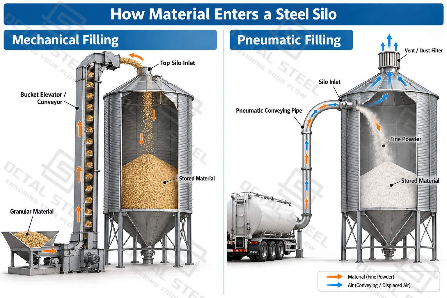
Filling capacity should be checked separately from silo storage capacity. A large silo does not shorten unloading time if the bucket elevator, conveyor or pneumatic line cannot accept material at the required rate. For pneumatic filling, the permitted transfer rate must also be considered together with the conveying-air conditions and the capacity of the silo venting and dust collection system.
What Happens After Material Enters the Silo?
Once material enters the silo, it begins to form the stored inventory rather than remaining as a simple layer of loose product. Continued filling increases both material level and stored mass, while the material may settle, segregate or consolidate depending on its physical characteristics and time at rest. During this stage, the silo must contain the stored material, maintain the required inventory, and provide sufficient information forthe control system to manage filling and later withdrawal.
| Storage Condition | What Happens Inside the Silo | Operational Significance |
|---|---|---|
| Material Accumulation | Incoming material raises the stored level and increases the total mass carried by the silo structure. | Stored mass depends on both usable volume and bulk density; volume alone does not indicate the actual material load. |
| Settling and Consolidation | Some bulk solids become more compact while remaining under their own weight, especially after longer periods at rest. | Consolidation can change the material condition encountered when discharge begins. |
| Segregation | Particles with different sizes, densities, or shapes may separate during conveying and deposition. | Product withdrawn from the silo may not always have exactly the same particle distribution as the material entering it. |
| Inventory Monitoring | Level instruments indicate whether the silo is approaching full, low, or intermediate inventory conditions. | Level information supports filling control, stock management, and continuity of downstream supply. |
| Condition Monitoring Where Required | Some stored materials require additional monitoring or management, such as temperature monitoring and aeration for grain. | Monitoring functions should be selected for the stored material rather than applied as one standard package to every silo. |
The condition of the stored material at the start of discharge may therefore differ from its condition when it first entered the silo. This is particularly important for materials that consolidate, absorb moisture, segregate or remain in storage for extended periods. The discharge system must deal with the material as it exists after storage, not simply with the condition assumed from the incoming product specification.
How Does Material Leave a Steel Silo?
A silo discharge system transfers stored material through the lower section of the silo and into downstream conveying, feeding, weighing, or processing equipment. In many installations, gravity provides the initial driving force: once the outlet is opened, material above it moves downward as space becomes available. The actual discharge behavior, however, is controlled by the interaction between the stored material and the silo geometry rather than by gravity alone.
For free-flowing bulk solids, gravity discharge may be relatively straightforward. Cohesive powders can behave differently because cohesive strength, wall friction, consolidation, hopper geometry, and outlet size influence whether material moves toward the outlet continuously. These factors determine the internal flow pattern and whether part of the stored inventory remains stationary during withdrawal.
Mass Flow and Funnel Flow
The movement of material inside the silo during discharge generally follows either mass flow or funnel flow. The distinction describes how much of the stored material is moving while material is being withdrawn and whether stationary regions remain within the silo.
| Flow Pattern | Movement During Discharge | Operational Characteristic |
|---|---|---|
| Mass Flow | Material moves throughout the active silo cross-section during withdrawal, including material adjacent to the walls. | Permanent stagnant regions are avoided, and material generally follows a first-in, first-out sequence. |
| Funnel Flow | Material initially moves through a flow channel above the outlet while material outside the channel remains stationary. | Material near the walls may remain in storage until the level falls; first-in, last-out behavior and stagnant regions can occur. |
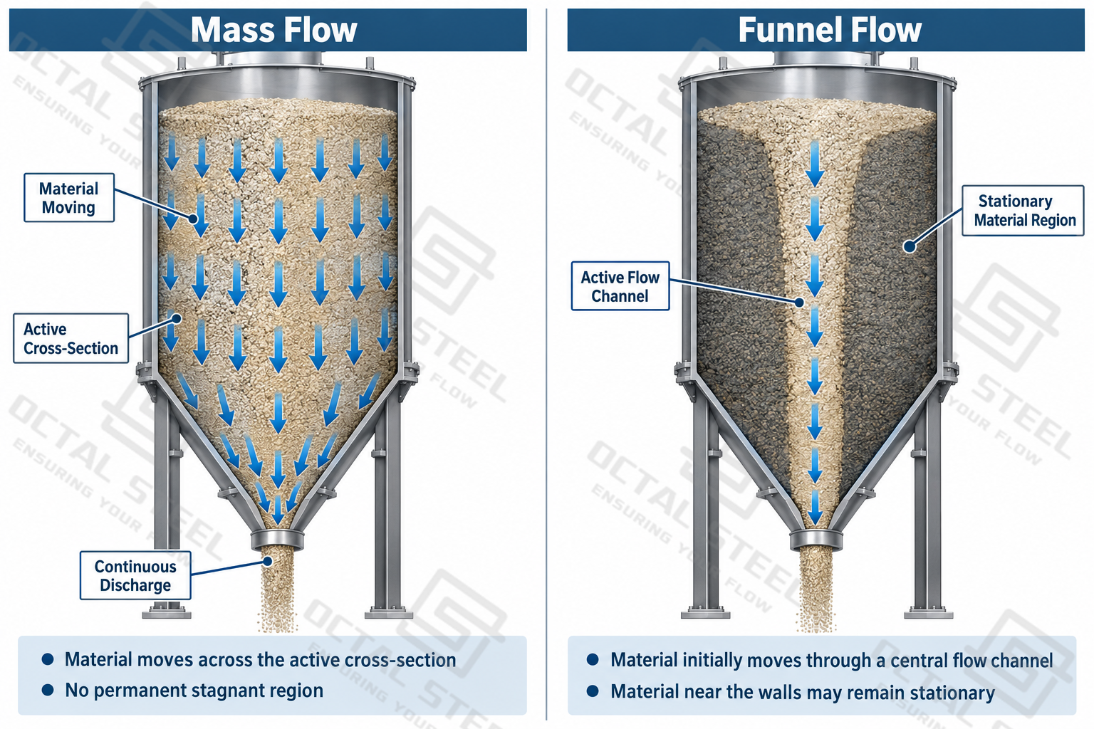
Whether mass flow or funnel flow develops depends on the bulk-solid flow properties, hopper geometry, wall surface, outlet, and withdrawal arrangement. Funnel flow is not automatically a failure condition, but it leaves a larger proportion of the stored inventory stationary during part of the discharge cycle. This becomes important when the material is cohesive, sensitive to extended storage, or required to leave the silo in a controlled sequence.
When Can Discharge Become Restricted?
Material flow can become restricted when the bulk solid develops sufficient strength to resist movement toward the outlet. Bridging (arching) occurs when material forms a stable structure across the outlet and prevents the material above from moving downward. Ratholing occurs when a discharge channel forms above the outlet but the surrounding material remains sufficiently stable that it does not collapse into the channel, leaving part of the stored inventory unavailable for normal discharge.
The tendency for these conditions to develop depends on material cohesion, particle characteristics, moisture, consolidation time, wall friction, hopper geometry, and outlet dimensions. Where restricted flow is a concern, the discharge arrangement must therefore be considered together with the actual bulk-solid behavior; simply adding vibration or other flow assistance does not address every cause of poor discharge.
What Happens During a Complete Steel Silo Operating Cycle?
The individual stages of silo operation do not always occur separately. Once the silo is connected to an operating plant, material may enter storage, remain there for a period, or leave for downstream use according to the timing of upstream supply and process demand. The stored inventory changes continuously according to the balance between material entering and leaving the silo.
| Operating Condition | Material Movement | Change in Stored Inventory | Effect on Operation |
|---|---|---|---|
| Filling without discharge | Material enters while little or no material leaves. | Inventory increases. | Material accumulates until the required operating level is reached or filling stops. |
| Simultaneous filling and discharge | Material enters and leaves during the same operating period. | Inventory may increase, decrease, or remain relatively stable. | The direction of inventory change depends on the difference between incoming and outgoing flow rates. |
| Discharge without filling | Stored material continues to leave while no new material enters. | Inventory decreases. | Previously accumulated material continues to supply the downstream process. |
| Low-inventory operation | Withdrawal continues as the remaining inventory approaches the lower operating range. | Available inventory becomes limited. | Additional material must enter the silo in time if downstream supply is to continue. |
Download:Steel Silo Operating Conditions and Material Flow Assessment Guide
When the incoming material rate exceeds the outgoing rate, inventory increases. When withdrawal exceeds incoming supply, inventory decreases. If the two quantities are approximately balanced over the same operating period, the stored inventory can remain relatively stable even though material continues to move through the system.
This relationship explains the practical buffering function of a steel silo. Bulk material may arrive during a relatively short unloading or production period but be consumed gradually by the downstream process, while in other installations filling and withdrawal may occur at the same time. The available inventory between these two material flows allows upstream supply and downstream consumption to follow different operating schedules.
The required storage volume is therefore related not only to the total quantity of material to be stored, but also to how supply and consumption change over time. A complete operating cycle may include repeated periods of inventory build-up and drawdown rather than a simple sequence in which the silo is completely filled and then completely emptied.
How Is Material Transferred from the Silo to the Next Process?
Material reaching the silo outlet still has to be delivered at a rate and in a condition that the downstream system can accept. The required arrangement depends on whether the material can discharge reliably by gravity, whether its flow rate must be regulated, and whether material remaining away from the outlet requires active reclaim. Controlled feeding, mechanical reclaim, and flow assistance therefore perform different functions and should not be treated as interchangeable discharge methods.
| Arrangement | Primary Function | Typical Operating Condition | How It Works | Main Engineering Consideration |
|---|---|---|---|---|
| Feeder-Controlled Discharge | Regulates material delivery to downstream equipment | Material reaches the outlet but must be supplied at a controlled rate | A screw feeder, belt feeder, rotary device, or other suitable feeder withdraws material and meters it into the next conveying or process stage | Feeder capacity and withdrawal pattern must match both silo flow and downstream demand |
| Mechanical Reclaim | Moves stored material toward the discharge point | Used where gravity alone cannot recover material across the storage floor, particularly in some flat-bottom silos | Reclaim equipment moves material from areas away from the outlet toward the discharge system | Reclaim capacity must reflect the required discharge duty and the quantity not recoverable by gravity |
| Flow Assistance | Helps suitable difficult-flowing material continue moving toward the outlet | Applied where material behavior limits reliable gravity flow | Aeration, fluidization, vibration, or another suitable method modifies or assists material movement near the hopper or discharge region | The method must suit the actual flow problem; it should not compensate for an unsuitable hopper or outlet design |
Controlled feeding, mechanical reclaim, and flow assistance may operate together as parts of the same discharge system. Their capacities and operating sequences need to be coordinated so that material movement toward the outlet, withdrawal from the silo, and transfer to downstream equipment remain compatible. Where flow assistance changes the condition of the material at the outlet, the feeder or conveying equipment must also accommodate the resulting flow behavior. The required silo discharge system should therefore be based on both bulk-solid flow characteristics and the feed conditions required by the downstream process.
How Do the Operating Stages of a Steel Silo Work Together?
The operating stages of a steel silo are interconnected rather than independent. Filling capacity determines how quickly material can enter storage, the storage section must accommodate both inventory and material condition, and the discharge system must deliver material at a rate the downstream process can accept. A mismatch at any of these interfaces can limit the performance of the complete material-handling system.
| Operating Requirement | Must Be Matched With | What Can Happen If They Do Not Match |
|---|---|---|
| Filling Rate | Receiving and conveying capacity | Trucks, upstream equipment, or conveying lines may wait even when storage volume is available |
| Stored Material Behavior | Wall surface, bottom, hopper, and outlet arrangement | Arching, ratholing, stagnant material, or irregular discharge may occur |
| Pneumatic Filling Rate | Venting and filtration capacity | Filling-air and dust handling can become the operating constraint |
| Required Discharge Rate | Outlet, feeder, and downstream demand | The silo may contain sufficient inventory but still starve the next process |
| Flat-Bottom Storage Duty | Outlet and reclaim arrangement | Part of the inventory may remain outside the active discharge region |
| Inventory Management | Appropriate level and condition monitoring | Operators may have insufficient information for filling, storage, or withdrawal control |
The capacities of these stages do not need to be identical. A steel silo provides the inventory buffer that allows receiving, storage, and downstream consumption to operate at different rates and at different times. What matters is whether the available storage volume can absorb the expected difference between incoming and outgoing material over the required operating period. The silo therefore functions effectively only when its usable capacity and the capacities of the connected handling equipment are matched to the actual operating cycle.
In operation, a steel silo works by receiving bulk material, holding it as available inventory, and releasing it when required by the downstream process. Material movement through the silo is influenced by the filling method, the behavior of the stored bulk solid, and the way material moves toward and through the outlet. This is why silo operation must be considered as a continuous material-handling process rather than simply the filling and emptying of a storage vessel.
FAQ
Q:Can a steel silo be filled and discharged at the same time?
A:Yes. In many systems, filling and discharge can occur during the same operating period. Inventory increases when the incoming material rate exceeds the withdrawal rate and decreases when discharge is faster than incoming supply. The connected handling equipment must be suitable for the required operating duty.
Q:Does material always flow out of a steel silo by gravity?
A:No. Gravity can move material toward the outlet, but it does not guarantee complete or stable discharge. Cohesive powders, consolidated materials, and material in some flat-bottom silos may require suitable reclaim equipment or flow assistance.
Q:Stored inventory does not guarantee sufficient discharge. Arching, ratholing, incomplete reclaim, or limitations at the outlet or feeder can restrict withdrawal and A:prevent material from reaching the downstream process at the required rate.
Q:Why does a steel silo need venting during pneumatic filling?
A:Pneumatic filling introduces both material and conveying air into the silo. The solids remain in storage, while conveying and displaced air must leave through an appropriate venting and filtration system. Venting capacity therefore needs to suit the actual pneumatic filling conditions.



Tags:steel platesteel plate manufacturersteel silo
Related Products
Related Resources

Recent Faqs
Rencent Articles
Hot Topic

Custom Posts

Octal is located in China recognized as a leading supplier, distributor, and manufacturer union in providing piping solutions for oil and gas company. Product ranges in Steel Pipe, Casing and Tubing, Steel Plate, Sucker Rod, Steel Pipe Fittings, Valves, and Equipment for pipelines.
Contact Info
Unit 2544, 25/F, Tower A, Wanda Plaza, Wenfeng District, Anyang, Henan, China & Building A, No.18 Dirun Road, Zhengdong New District, Zhengzhou, Henan, China
+86 372 2157660 / +86 186 3727 1277
[email protected]