Your Responsible Supplier Partner for Oil and Gas Products.
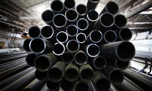
3LPE Coated Pipe
Recent Products
Rencent Articles

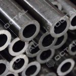
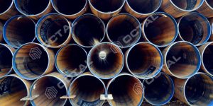

3LPE Coated Pipe
Diameter Range: 4″ to 60″
Grades: API 5L Grade B, X42–X80
Pipe Types: Seamless, ERW/HFW, LSAW, SSAW
Coating Structure: FBE + adhesive + polyethylene
Reference Thickness: Approx. 1.8–3.7 mm
Standards: API 5L, ISO 3183, ISO 21809-1, DIN 30670-1
Applications: Buried and submerged oil, gas and water pipelines
3LPE coated pipe provides corrosion protection, strong adhesion and resistance to impact, moisture and abrasion.
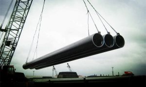
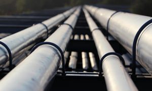
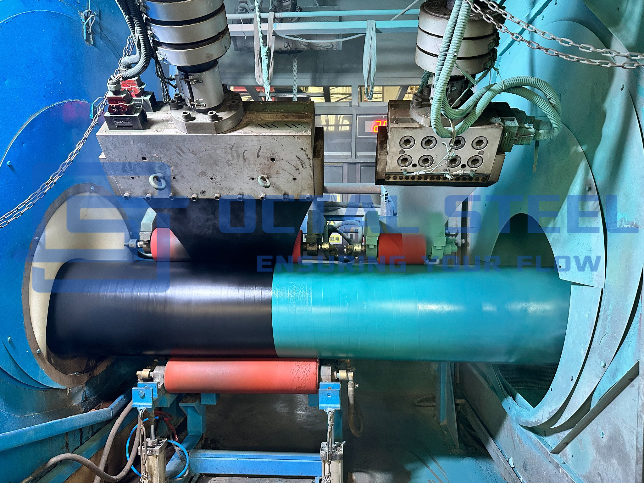
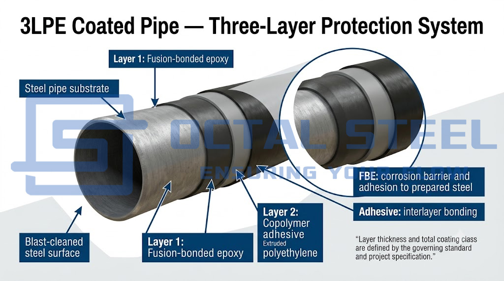
3LPE coated pipe (three-layer polyethylene coated pipe) is protected by a fusion-bonded epoxy primer, a copolymer adhesive and an extruded polyethylene topcoat. The coating system is applied to seamless or welded steel line pipe. The FBE primer is applied directly to the blast-cleaned and heated steel surface, creating the primary corrosion-protection interface; the adhesive provides chemical and mechanical bonding between the epoxy and polyethylene; and the PE topcoat supplies the thickness, toughness and moisture resistance needed to protect the pipe during lifting, transportation, storage, trench lowering and backfilling. The system is commonly specified for buried or submerged oil, gas and water transmission pipelines, gathering lines, river crossings and routes through wet or corrosive soil where corrosion resistance must be combined with protection against impact, indentation and abrasion. For HDD pullback, rocky backfill, elevated service temperature or concrete weight coating, the coating class, abrasion protection, cutback geometry and field-joint compatibility require project-specific qualification.
A 3LPE coating system shall be regarded as an integrated, standards-based corrosion-protection system engineered, qualified, and controlled for the specified service conditions, rather than as a simple combination of three coating layers. The coating shall provide effective resistance to soil-side contamination and anticipated thermal cycling; however, these properties shall not be used to compensate for incomplete FBE coverage, inadequate FBE cure, or insufficient adhesive bonding.
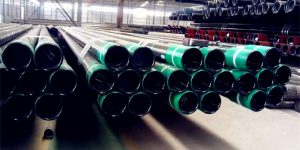
Octal Steel supplies 3LPE coated pipes with seamless, HFW/ERW, LSAW and SSAW base pipes for buried and submerged oil, gas and water transmission pipelines. Base-pipe and coating requirements can be coordinated with API Spec 5L, ISO 3183, ISO 21809-1, DIN 30670-1, CSA Z245.21 and approved project specifications. The following table separates the function and main acceptance concern of each layer in the 3PE coating system.
| Coating Layer | Material | Engineering Function | Main Acceptance Concern |
|---|---|---|---|
| First layer | Fusion-bonded epoxy | Bonds to the prepared steel and provides the principal corrosion-protection interface | Surface cleanliness, profile, application temperature, cure and film continuity |
| Second layer | Copolymer or grafted adhesive | Chemically and mechanically connects the epoxy to the polyethylene topcoat | Material compatibility, extrusion temperature and application window |
| Third layer | Extruded polyethylene | Provides moisture resistance and protects the underlying layers against impact, indentation and abrasion | Total thickness, continuity, impact resistance and handling damage |
3LPE Coated Pipe Specifications
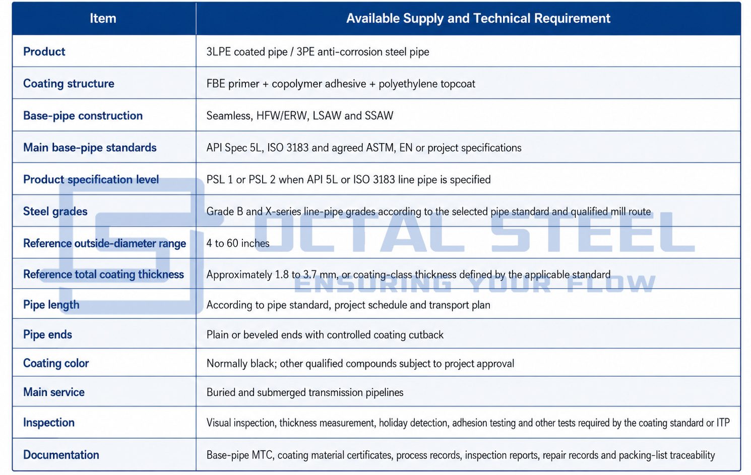
The 4–60 inch supply range and approximately 1.8–3.7 mm reference coating range . Final availability depends on base-pipe dimensions, coating-line capacity, coating class and project qualification.
Download:3LPE_Coated_Pipe_Specification_and_Ordering_Guide.pdf
3LPE Pipe Standards and Compliance
The base pipe and external coating are governed by different technical documents. The base-pipe certificate confirms the steel product. It does not by itself confirm that the external coating complies with the project coating specification.
| Standard | Scope in a 3LPE Pipe Order |
|---|---|
| ISO 21809-1:2018 | Plant-applied external three-layer PE and PP coatings for buried or submerged steel pipelines |
| DIN 30670-1:2024 | Factory-applied extruded polyethylene coatings on steel pipes and fittings |
| CSA Z245.21:22 | Qualification, application, inspection, testing, handling and storage of plant-applied polyethylene coating for steel pipe |
| API Spec 5L | Manufacturing and acceptance requirements for seamless and welded steel line pipe |
| ISO 3183:2019 | PSL 1 and PSL 2 seamless and welded steel pipe for pipeline transportation systems |
| ISO 8501-1 | Visual assessment of steel-surface cleanliness before coating |
| ISO 8502 series | Assessment of dust, soluble salts and other surface contaminants |
| ISO 8503 series | Measurement and assessment of blast-cleaned surface profile |
| Project coating specification | Temperature class, thickness class, cutback, testing frequency, acceptance criteria and documentation |
ISO 3183:2019 remains current after its 2026 review and covers PSL 1 and PSL 2 seamless and welded pipeline steel pipe. DIN lists DIN 30670-1:2024 as the current factory-applied extruded PE coating standard, while CSA Z245.21:22 includes coating qualification, application, inspection, testing, handling and storage requirements.
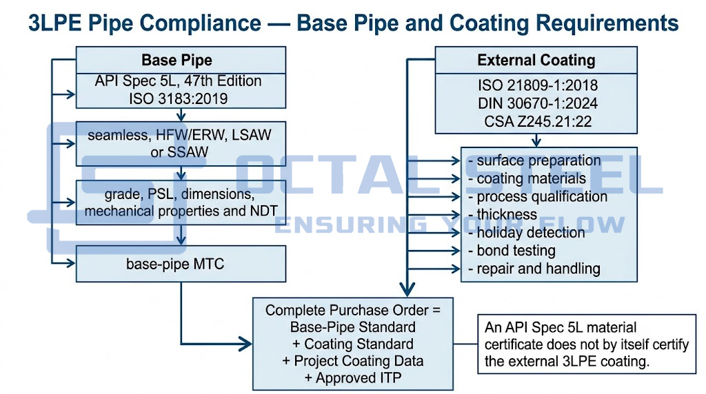
A purchase order should therefore identify both documents, for example:
API Spec 5L PSL 2 line pipe with external 3LPE coating in accordance with ISO 21809-1, including the specified coating class, design temperature, minimum thickness, cutback and project ITP.
Writing only “API 5L 3LPE pipe” leaves the coating class and acceptance requirements incomplete.
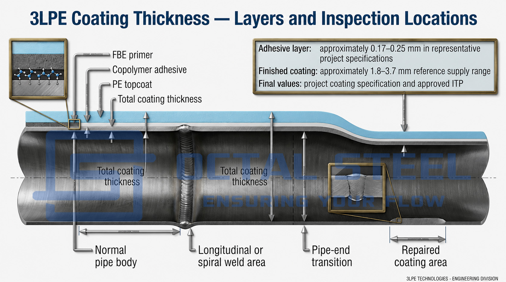
Representative 3LPE Coating Thickness
The total thickness of a 3LPE pipe is controlled by pipe diameter, coating class, service temperature, handling risk and project specification. It should not be treated as one universal value.
A representative system may include:
- FBE primer: normally specified as a minimum dry-film thickness;
- adhesive layer: commonly around 0.17–0.25 mm in project specifications;
- PE topcoat: adjusted to meet the required total thickness;
- total finished coating: commonly within approximately 1.8–3.7 mm for standard product ranges.
These figures are reference values, not automatic acceptance criteria. Published operator specifications show that minimum total thickness can change by pipe OD. One public project specification, for example, defines 2.5, 2.8, 3.0 and 3.3 mm minimum thickness categories for increasing pipe-diameter groups.
The RFQ should state:
- minimum FBE thickness;
- minimum adhesive thickness;
- minimum total coating thickness;
- normal or reinforced coating class;
- permissible local under-thickness;
- thickness measurement frequency;
- whether additional abrasion-resistant protection is required.
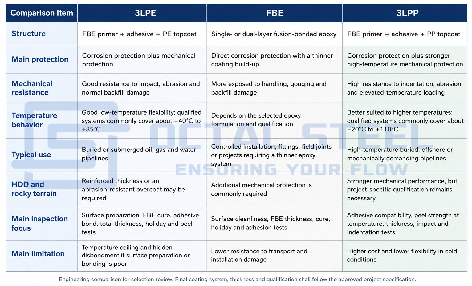
3LPE vs FBE vs 3LPP Coating
FBE, 3LPE and 3LPP are related plant-applied pipeline coating systems. FBE forms the direct corrosion barrier on the prepared steel surface and may be used alone or as the primer layer in 3LPE and 3LPP systems. 3LPE adds an adhesive and polyethylene topcoat for improved impact, abrasion and moisture resistance, while 3LPP uses polypropylene to provide stronger performance at elevated temperatures.
The choice between these systems depends on operating temperature, installation method, soil and backfill condition, handling risk, field-joint compatibility and the qualified limits of the complete coating system. The table below compares their structure, service behavior, inspection focus and main selection constraints.
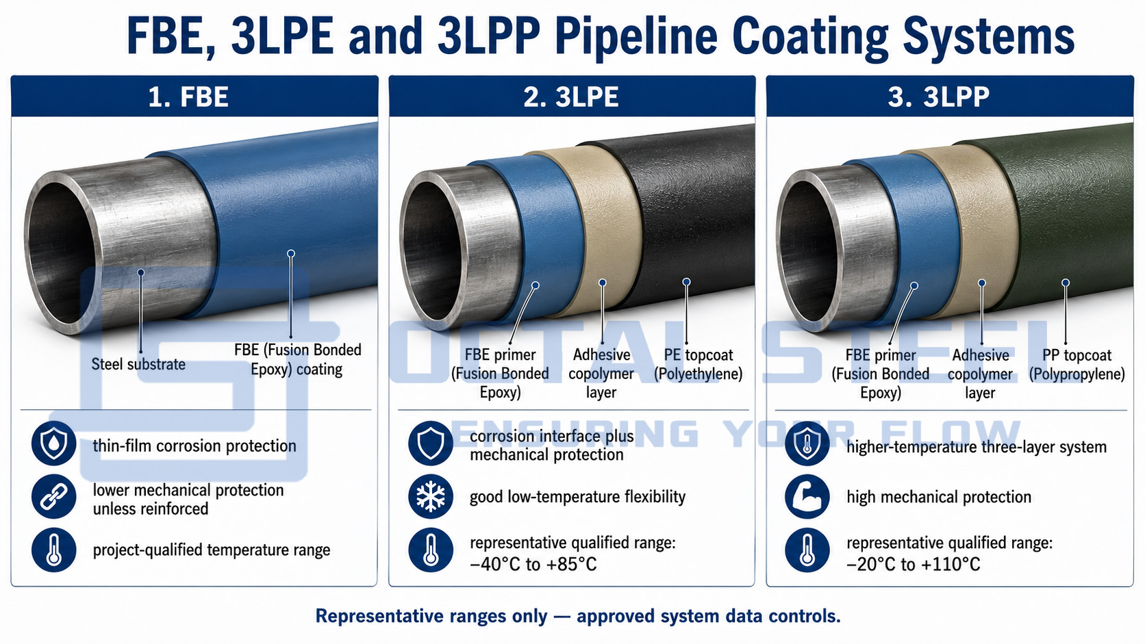
The temperature ranges shown are representative qualified-system values. Final selection should follow the approved coating data sheet, operating temperature, installation method, backfill condition and project specification.
Download:3LPE_vs_FBE_vs_3LPP_Coating_Selection_Guide_Final.pdf
3LPE Compared with 2LPE
A two-layer PE system normally omits the separate FBE primer or uses a simplified primer/adhesive arrangement. A full 3LPE system provides a distinct epoxy-to-steel corrosion barrier, a bonding layer and a separate mechanical topcoat.
The two systems should not be treated as interchangeable. The project must confirm:
- whether an FBE primer is mandatory;
- required cathodic-disbondment performance;
- temperature class;
- thickness class;
- test methods;
- compatibility with the field-joint coating.
3LPE Coated Pipe Weight
The weight of a finished coated pipe is the sum of the bare steel-pipe mass and the mass of all coating layers.
For each coating layer:

Where:
- mim_i = coating mass per metre;
- = outside diameter after applying that layer;
- = diameter before applying that layer;
- = density of the coating material.
The total coated-pipe mass is:
mtotal=msteel+mFBE+madhesive+mPE
For shipment planning, the calculation should also consider:
- uncoated cutback length at both ends;
- actual average coating thickness;
- couplings, end protectors or temporary caps;
- repair material;
- bundle, cradle and packing weight.
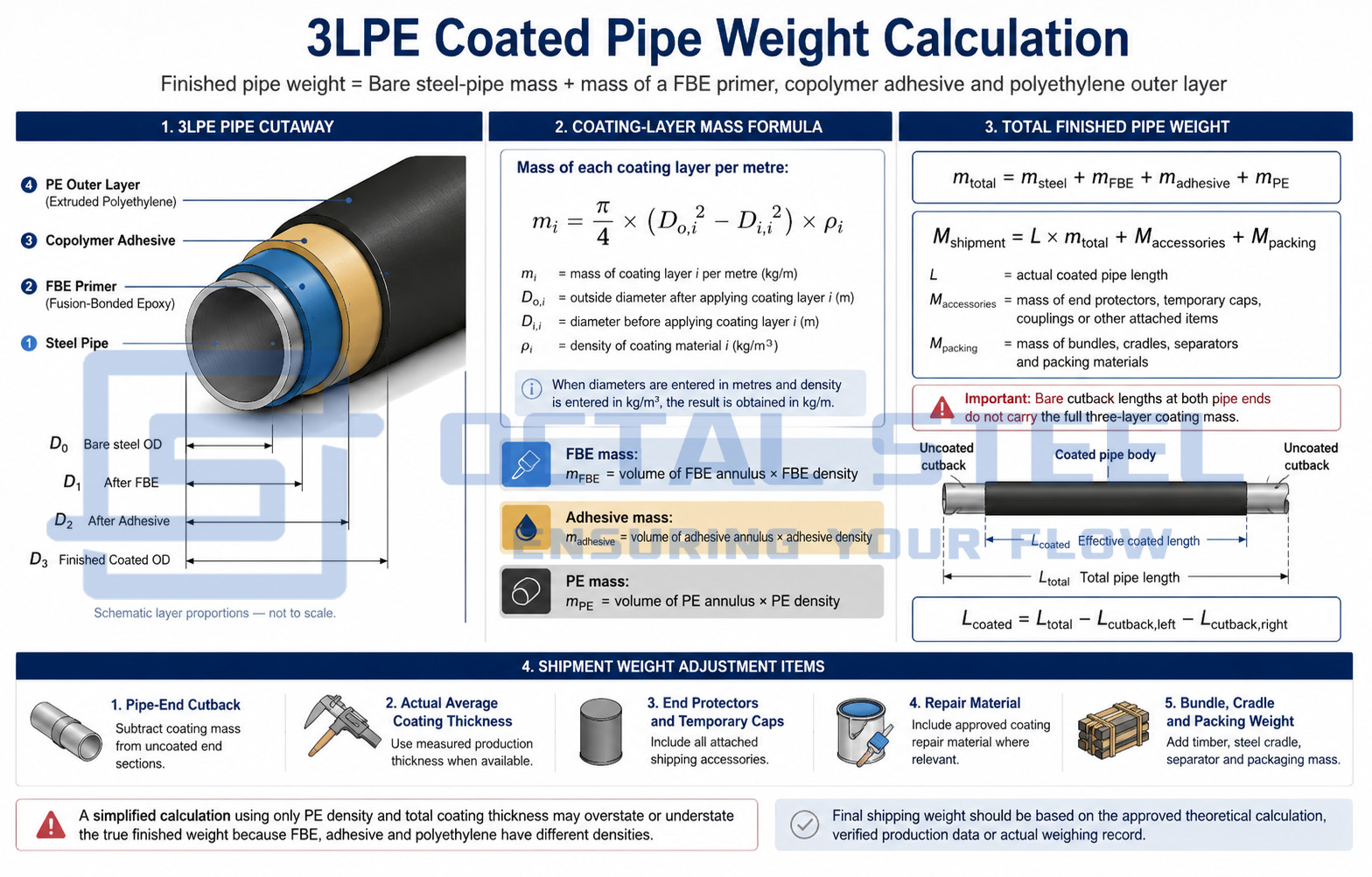
A simplified calculation using only PE density and total coating thickness can overstate or understate the true value because FBE, adhesive and polyethylene have different densities. Final shipping weight should be based on the approved theoretical calculation or actual production weight record.
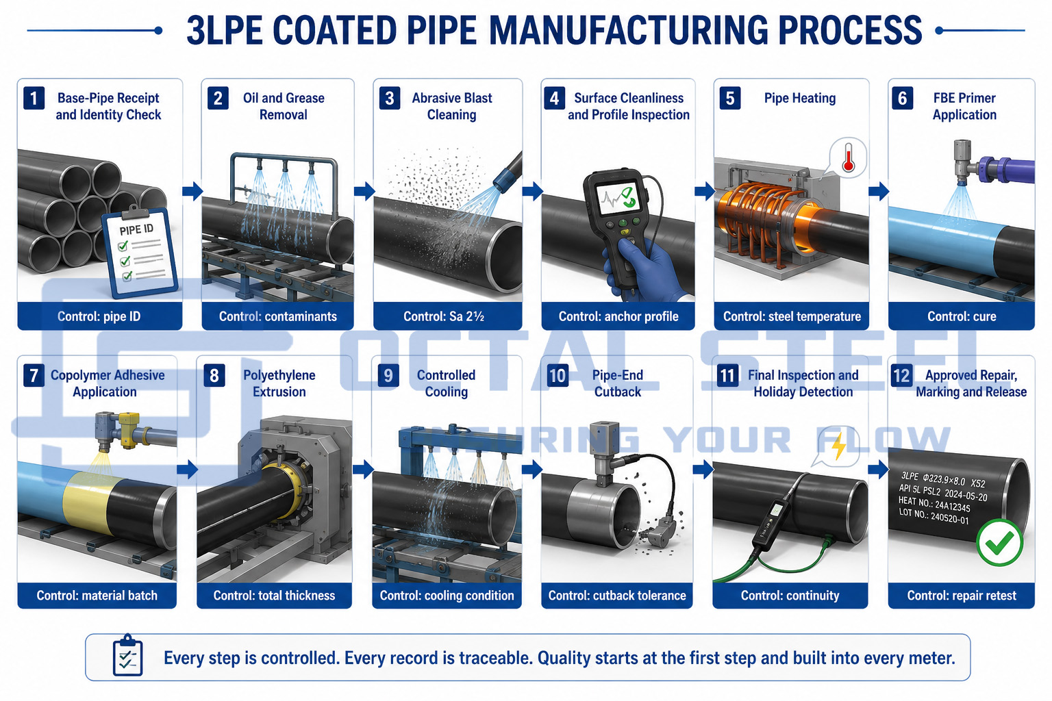
3LPE Coating Manufacturing Process
1. Base-Pipe Receipt and Identity Check
Each pipe is received against its manufacturing records. The pipe number, heat number, standard, grade, OD, wall thickness, length and end preparation are checked before coating.
Surface defects that may interfere with coating application—such as slivers, weld spatter, deep scratches, laminations or sharp projections—are identified and dispositioned. Grinding must not reduce the remaining wall thickness below the base-pipe acceptance requirement.
2. Oil, Grease and Contaminant Removal
Oil, grease, salts, marking adhesive and other contaminants are removed before abrasive blasting. Blasting a contaminated surface can drive residue into the profile and reduce long-term epoxy adhesion.
The cleaning record should identify the method, consumables and inspection result.
3. Abrasive Blast Cleaning
The external pipe surface is blast-cleaned to the cleanliness grade required by the approved coating specification, commonly near-white metal equivalent to Sa 2½ under ISO 8501-1.
The prepared surface is checked for:
- visual cleanliness;
- anchor profile;
- dust contamination;
- soluble salts when required;
- re-exposed steel defects;
- moisture or flash rust.
ISO 8501-1 defines visual preparation grades, while ISO 8503 procedures are used to assess blast-cleaned surface profile.
4. Pipe Heating
The pipe is heated to the qualified FBE application temperature. Temperature is measured with calibrated instruments and recorded against line speed, pipe diameter and wall thickness.
The approved temperature window must follow the coating material supplier’s data and the qualified Application Procedure Specification. Applying FBE below the qualified window can reduce cure and adhesion. Excessive temperature can damage the powder or alter the interaction between the epoxy and adhesive.
5. FBE Primer Application
Electrostatically charged epoxy powder is sprayed onto the heated steel. The powder melts, flows and begins to cure, forming the primary anti-corrosion layer.
FBE application control includes:
- powder batch;
- virgin-to-reclaimed powder ratio where recycling is permitted;
- spray-gun condition;
- pipe temperature;
- line speed;
- gel and cure behavior;
- minimum dry-film thickness.
6. Adhesive Application
The copolymer adhesive is applied while the FBE remains within the qualified bonding window. Its application timing is critical: the layer must interact correctly with the epoxy while also accepting the polyethylene topcoat.
Extrusion temperature, flow rate and time between FBE and adhesive application are recorded.
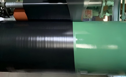
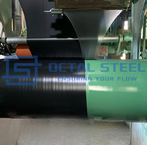
7. Polyethylene Extrusion
The outer PE layer is applied by extrusion and pressed onto the adhesive to avoid trapped air, weak overlap areas and voids near longitudinal or spiral weld seams.
The topcoat thickness is controlled to achieve the specified overall coating class.
8. Cooling and Quenching
The coated pipe is cooled under a qualified procedure until it can be handled and inspected without deformation or damage to the coating.
Cooling conditions should not introduce cracking, warping, delamination or uncontrolled residual stress.
9. Pipe-End Cutback
The coating is removed or terminated at each pipe end to allow field welding and field-joint coating.
The order should define:
- cutback length;
- dimensional tolerance;
- coating edge angle;
- exposed steel condition;
- adhesive termination;
- temporary protection of the bare end;
- compatibility with automatic or manual welding.
A published operator specification uses 120 mm with a +20/−0 mm tolerance as a standard cutback and 150 mm with the same tolerance where automatic welding requires additional space. Those values are project-specific examples rather than universal dimensions.
10. Final Inspection, Repair and Marking
Each pipe undergoes visual inspection, coating-thickness verification and holiday detection. Permitted coating damage is repaired using an approved system and reinspected using the same applicable acceptance method.
The original pipe identity is then restored on the finished 3PE anti-corrosion steel pipe.
Public operator specifications require documented control of surface preparation, pipe heating, FBE application, adhesive and PE extrusion, quenching, cutback preparation, instrument calibration, repairs and coated-pipe handling.

3LPE Coated Pipe Inspection and Acceptance
A reliable 3pe coating system is confirmed through process records and finished-product testing rather than visual appearance alone.
| Inspection Point | How It Is Checked | What It Confirms | Risk Controlled |
|---|---|---|---|
| Pipe identity | Marking and document review | Correct base pipe enters coating production | Grade or heat-number mix-up |
| Surface cleanliness | Visual comparator and approved procedure | Mill scale, rust and contamination have been removed | Low FBE adhesion |
| Surface profile | Profile gauge, comparator or replica tape | Sufficient mechanical key for epoxy | Premature disbondment |
| Dust and soluble salts | Tape or conductivity method where specified | Surface is not contaminated after blasting | Osmotic blistering and weak bonding |
| Application temperature | Calibrated pyrometer and continuous record | FBE is applied within the qualified temperature window | Under-cure or thermal degradation |
| FBE and adhesive thickness | Calibrated thickness measurement | Minimum individual layer requirement is achieved | Weak corrosion barrier or bonding |
| Total thickness | Measurements along pipe body and weld area | Required coating class is achieved | Impact and indentation damage |
| Visual inspection | 100% external surface | No wrinkles, voids, bubbles, tears or delamination | Hidden application defects |
| Holiday detection | Full-circumference electronic test at approved voltage | Coating continuity and absence of pinholes | Direct electrolyte contact with steel |
| Peel or bond-strength test | Strip-peel test at specified temperature | Bond between PE, adhesive, FBE and steel | Layer separation |
| Impact and indentation | Qualification or production testing | Resistance to handling, backfill and concentrated loads | Site damage |
| Cathodic disbondment | Laboratory test under specified temperature and voltage | Coating behavior adjacent to a defect under CP | Underfilm disbondment |
| Cutback inspection | Tape, profile gauge and visual examination | Correct welding and field-joint area | Fit-up and field-coating rework |
| Repair reinspection | Thickness and holiday retest | Repaired area meets release requirements | Undocumented local defects |
Inspection frequency must follow the selected standard and approved ITP. Some project specifications require visual examination and holiday testing over 100% of every pipe surface, while destructive tests such as peel, impact, indentation and cathodic disbondment are performed at defined qualification, shift, lot or daily frequencies.
Holiday-test voltage must not be copied from another project. It is selected according to the applicable standard, coating thickness and approved procedure.
Download:3LPE_Coated_Pipe_Inspection_and_Acceptance_Checklist_Revised.pdf
Applications by Installation Condition
Buried Transmission Lines in Wet or Corrosive Soil
During trench lowering and backfilling, the pipe is exposed to soil moisture, stones, contact pressure and handling loads. The PE outer layer limits abrasion and impact damage, while the FBE layer maintains the corrosion-protection interface at the steel surface.
Acceptance should focus on holiday detection, total thickness, peel strength and repair records before the pipe enters the trench.
Rocky Backfill and Mountain Pipeline Routes
Rocky routes create concentrated contact points during lowering-in and backfilling. Standard 3LPE may need a reinforced thickness class, selected padding or an additional abrasion-resistant overcoat.
The coating decision should be linked to backfill specification rather than assuming that any 3LPE pipe can tolerate unrestricted rock contact.
Horizontal Directional Drilling and Pullback
HDD pullback subjects the coating to continuous abrasion, shear and localized gouging. A project may require thicker PE, an abrasion-resistant overcoat or another qualified protective layer.
The review should include pull length, bore geometry, soil and rock condition, pulling force, coating thickness and repair plan.
River, Coastal and Submerged Pipeline Installation
For submerged pipelines, 3LPE provides the anti-corrosion system beneath any concrete weight coating or mechanical protection layer.
The interface between 3LPE and concrete weight coating must be qualified. Pipe-end geometry, anode attachment, field-joint coating and concrete-free cutback dimensions also require coordination.
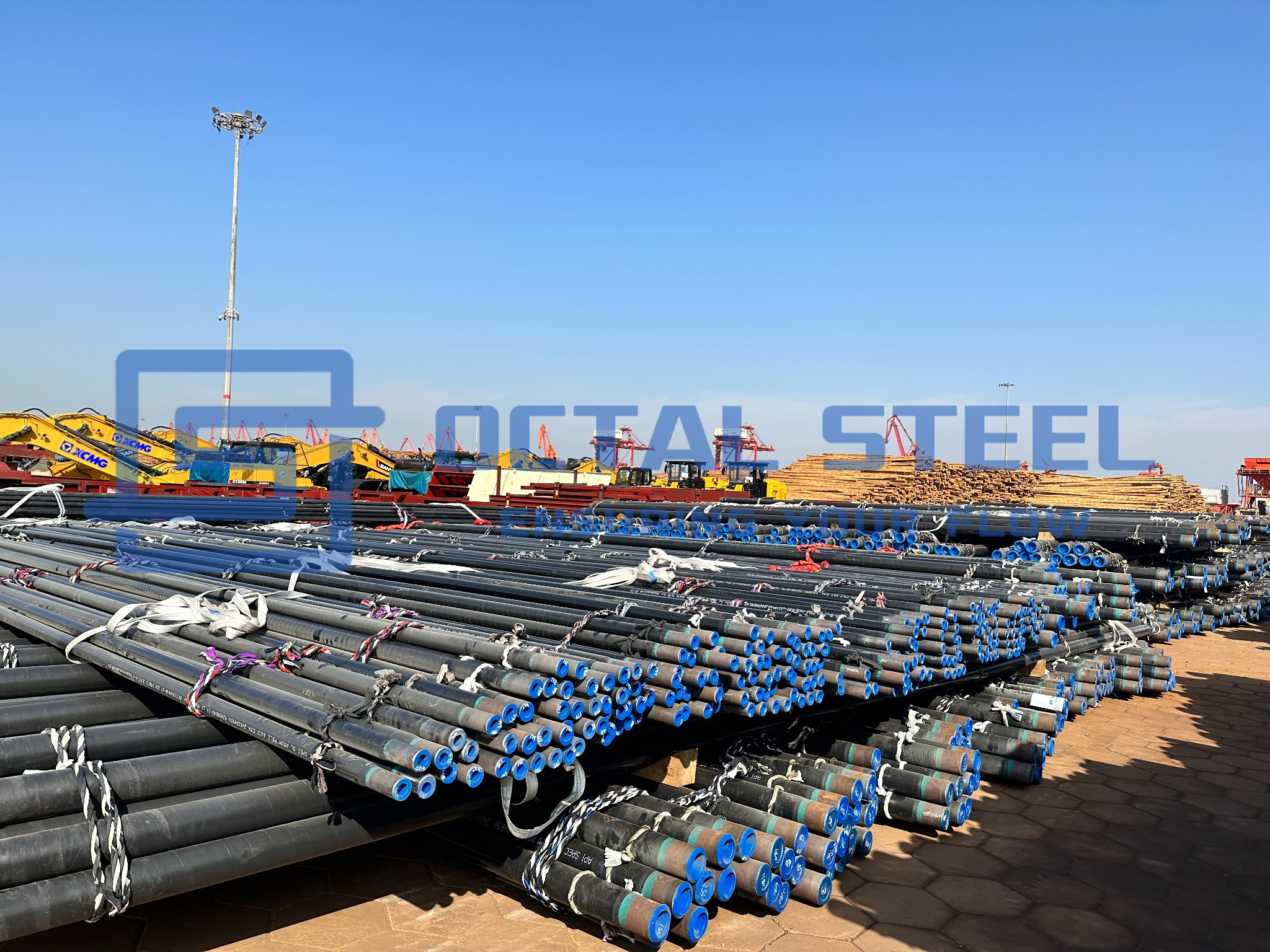
Long-Distance Gas and Oil Pipelines
Long hauling, repeated lifting, stockyard storage and continuous field welding increase the chance of coating damage before commissioning.
Inspection should continue through loading and shipment release. Final pipe-count and repair records must match the packing list and coating inspection dossier.
3LPE Coating Integrity Risks and Control Points
The integrity of a 3LPE coating system depends on more than the visible condition of the polyethylene topcoat. Surface preparation, application temperature, adhesive compatibility, coating thickness and production traceability all affect whether the coating will remain bonded during handling, installation and long-term service.
1. FBE Adhesion and Steel-Surface Preparation
Main risk: FBE disbondment beneath an apparently intact polyethylene layer.
Oil, salts, dust, insufficient blast profile or incorrect pipe-heating temperature can weaken the bond between the FBE primer and steel surface. Moisture may then migrate beneath the coating without producing an obvious external defect.
Control points:
- surface-cleanliness and profile records;
- dust and soluble-salt testing where specified;
- calibrated pipe-temperature monitoring;
- FBE application and cure records;
- peel-strength and cathodic-disbondment testing.
2. Bonding Between FBE, Adhesive and Polyethylene
Main risk: Separation of the PE topcoat during handling, cutting or field-joint preparation.
This normally results from incompatible coating materials, incorrect extrusion temperature or application outside the qualified bonding window.
Control points:
- approved FBE–adhesive–PE material combination;
- material batch verification;
- extrusion-temperature and line-speed records;
- Procedure Qualification Test documentation;
- production peel or bond-strength testing.
3. Coating Thickness and Weld-Seam Coverage
Main risk: Local weak areas with reduced impact, indentation or abrasion resistance.
Unstable extrusion, uneven line speed or insufficient pressure around longitudinal and spiral weld seams can create low-thickness areas or trapped air.
Control points:
- coating-thickness measurements along the pipe body;
- additional checks over LSAW, SSAW or HFW weld areas;
- weld-apex inspection;
- air-entrapment and overlap control;
- pipe-by-pipe thickness records where required by the ITP.
4. Pipe-End Cutback and Field-Joint Preparation
Main risk: Welding delays, poor fit-up or field-joint coating rework.
Incorrect cutback length, damaged coating edges or poorly prepared exposed steel can interfere with girth welding and subsequent field-joint coating.
Control points:
- cutback-length and tolerance measurement;
- coating-edge profile inspection;
- exposed-steel surface condition;
- pipe-end protection during storage and transport;
- compatibility review with the selected field-joint coating system.
5. Coating Damage and Repair Release
Main risk: Local defects are repaired but cannot be verified during final inspection or at the installation site.
Repairs performed without documented location, method or reinspection can interrupt the coating traceability chain.
Control points:
- approved repair-material system;
- defined maximum repair size;
- repair-location map;
- thickness and holiday retesting;
- repair and reinspection records linked to the pipe number.
6. Pipe and Coating-Lot Traceability
Main risk: The base pipe, coating materials or inspection results cannot be matched during final release.
Pipe identity may be lost during blasting or coating if marking transfer and batch control are not maintained.
Control points:
- continuous pipe-number tracking;
- heat-number and MTC verification;
- FBE, adhesive and PE batch records;
- coating production shift and inspection records;
- final marking linked to the packing-list pipe map.
The outer PE layer may remain visually undamaged even when adhesion beneath it has already deteriorated. For this reason, surface-preparation records, process-temperature control, peel testing and cathodic-disbondment results provide stronger acceptance evidence than coating appearance alone.
Download:3LPE_Coating_Integrity_Risks_and_Control_Points_Balanced.pdf
Documentation and Traceability
A complete release package should maintain the following identity chain:
Pipe marking → heat number → base-pipe MTC → pipe number → coating material batches → coating production shift → process temperature record → thickness and holiday reports → destructive test results → repair and reinspection record → final marking → packing-list pipe map → shipment release
Recommended documents include:
- EN 10204 3.1 base-pipe material certificate;
- base-pipe dimensional and NDT reports;
- coating material certificates for FBE, adhesive and PE;
- approved Application Procedure Specification;
- Procedure Qualification Test report;
- Inspection and Test Plan;
- instrument calibration certificates;
- surface-preparation records;
- application-temperature and extrusion records;
- coating-thickness report;
- holiday-detection report;
- peel-strength and production-test reports;
- repair log and repair-location map;
- pipe-end cutback report;
- final visual inspection record;
- packing list linked to pipe numbers or coating lots;
- third-party inspection release where specified.
Public operator specifications require batch-level coating material certification, coating procedures, PQT documentation, calibration records, production logs, test reports and handling procedures before production release.
FAQ
What should be included in a 3LPE coated pipe RFQ?
State the base-pipe standard, grade, PSL, OD, wall thickness, length and pipe type. Also define the coating standard, temperature class, minimum layer thickness, total thickness, cutback, inspection scope, repair limits and required documents.
Which standard applies to 3LPE coating?
The main international standard is ISO 21809-1:2018. Projects may also specify DIN 30670-1:2024 or CSA Z245.21:22. The steel pipe itself should be ordered separately to API 5L, ISO 3183 or another approved base-pipe standard.
Does API 5L cover the 3LPE coating?
No. API 5L covers the steel line pipe, not the external coating system. 3LPE compliance requires coating-material certificates, an approved application procedure, PQT, ITP and coating inspection reports.
How is 3LPE coating thickness specified?
Thickness depends on pipe OD, coating class, service temperature, handling risk and project specification. The RFQ should state minimum FBE thickness, adhesive thickness and total coating thickness. One universal thickness should not be used for every project.
What is the difference between 3LPE and FBE?
FBE is a single epoxy layer bonded directly to prepared steel. 3LPE adds a copolymer adhesive and polyethylene topcoat, giving stronger resistance to impact, abrasion, indentation and handling damage.
Social Share