Your Responsible Supplier Partner for Oil and Gas Products.
API 650 Tanks
Recent Products
Rencent Articles


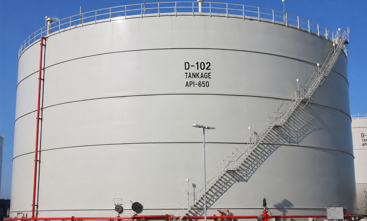
API 650 Tanks
Standard: API 650, project-specified edition
Tank Type: Vertical, cylindrical, aboveground welded steel tank
Service: Near-atmospheric oil, fuel, water, and liquid storage
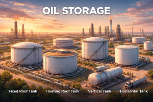
Roof Options: Fixed roof, internal floating roof, external floating roof
Materials: Carbon steel, stainless steel, or duplex stainless steel
Construction: Field-erected shell, bottom, roof, nozzles, and accessories
Inspection: Weld NDE, bottom leak test, dimensional survey, and hydrostatic test
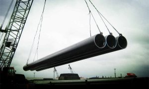
API 650 tanks are vertical, cylindrical, aboveground welded tanks built with a fully supported bottom for the storage of crude oil, refined fuels, water, wastewater and other non-refrigerated liquids. The tank is assembled as a complete structure consisting of the bottom, shell courses, roof, nozzles, manways, reinforcement plates, wind girders, access systems and operating accessories.
Unlike a pressure vessel, Octal Steel’s API 650 tank is designed primarily around liquid head, tank diameter, shell height, stored-liquid density, wind, seismic action, roof loading and foundation behavior. The lower shell courses carry the highest hydrostatic load and are normally thicker than the upper courses. Roof type, bottom configuration, corrosion allowance, material grade, vent capacity and nozzle arrangement are then selected around the actual storage duty rather than from a fixed catalogue size.
API 650 establishes minimum requirements for materials, design, fabrication, erection and inspection of open-top and closed-top welded storage tanks operating at pressures approximately atmospheric. The standard does not prescribe a fixed series of tank capacities or dimensions, allowing the diameter and height to be engineered around the required storage volume and site limitations.
API 650 Storage Tank Specifications
| Item | Available Design Scope |
|---|---|
| Governing standard | API 650, edition and contractual supplements specified by the project |
| Tank form | Vertical, cylindrical, aboveground welded steel tank |
| Bottom support | Entire tank bottom uniformly supported by the foundation |
| Basic pressure basis | Approximately atmospheric; additional design requirements apply where higher internal pressure is specified |
| General temperature range | Non-refrigerated service with maximum design temperature up to 93°C (200°F) under the basic scope |
| Elevated-temperature route | Additional Annex M requirements from above 93°C to a maximum of 260°C (500°F) |
| Capacity | Engineered according to gross volume, working volume, freeboard, and operating level |
| Roof configurations | Fixed cone roof, dome roof, supported roof, internal floating roof, external floating roof, or open top |
| Bottom configurations | Flat bottom, cone-up bottom, cone-down bottom, annular plate arrangement, or double-bottom system |
| Main materials | Carbon steel, austenitic stainless steel, or duplex stainless steel, subject to the applicable design route |
| Construction method | Field erection from prepared plates and prefabricated components; shop assembly where transportable dimensions and the selected design route permit |
| Corrosion protection | Corrosion allowance, internal lining, external coating, bottom-side protection, and cathodic protection where specified |
| Inspection | Material verification, dimensional control, weld examination, bottom leak testing, hydrostatic testing, and coating inspection |
| Accessories | Nozzles, manways, vents, drains, overflow connections, ladders, stairways, platforms, level instruments, and heating systems |
The standard’s basic scope covers non-refrigerated tanks up to 93°C (200°F). Annex M provides additional requirements for tanks operating above this temperature and up to 260°C (500°F). API published the 14th Edition in August 2025, with an API Monogram Program effective date of March 1, 2026. The purchase order should still identify the exact edition instead of relying only on the phrase “latest edition.”
API 650 Tank Capacity, Diameter and Shell Height
API 650 does not define a mandatory series of standard capacities. Tank dimensions are selected by balancing working volume, available plot area, allowable height, soil-bearing capacity, shell plate availability, wind exposure, seismic demand and operating access.
The basic cylindrical volume is calculated from:
Gross cylindrical volume = π × diameter² × liquid height ÷ 4
For illustration, a tank with a 30 m internal diameter and 14.15 m cylindrical liquid height has a gross geometric volume of approximately 10,000 m³. This is not the usable operating volume. Freeboard, floating-roof displacement, high-high level margin, dead stock below the outlet, bottom slope, internal columns and minimum operating heel must be deducted or separately considered.
| Capacity Term | Meaning |
|---|---|
| Gross capacity | Total geometric volume within the defined tank dimensions |
| Working capacity | Volume available between the normal minimum and maximum operating levels |
| Maximum operating capacity | Volume at the approved maximum operating liquid level |
| Overfill protection level | Independent level used by the overfill prevention system |
| Freeboard | Vertical clearance retained above the maximum operating liquid level |
| Dead stock | Liquid below the lowest practical withdrawal or pumpable level |
| Net usable capacity | Volume available for normal storage and transfer operations |
A tall, narrow tank uses less plot area but produces a greater liquid head and higher lower-shell stress. A wider tank reduces liquid height for the same capacity but increases bottom area, roof span, foundation footprint and settlement sensitivity. Diameter and height therefore need to be selected together.
Internal and External Construction of an API 650 Tank
The tank functions as a connected structural system. Changing one component can alter loads and detailing elsewhere. A heavier roof changes compression-ring behavior; a larger nozzle increases local shell reinforcement; an internal floating roof affects clearances and operating volume; a double bottom changes foundation elevation and leak-monitoring arrangements.
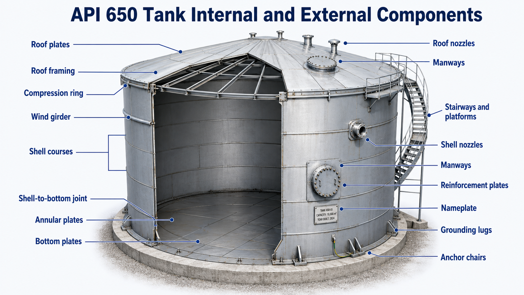
| Tank Component | Construction and Function |
|---|---|
| Bottom plates | Form the liquid-retaining floor and transfer liquid and dead loads to the foundation. |
| Annular plates | Provide a controlled plate zone beneath the shell where shell-to-bottom stresses are concentrated. |
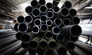
| Shell courses | Rolled plate rings joined by vertical and circumferential welds; thickness normally reduces toward the top. |
| Shell-to-bottom joint | Connects the vertical shell to the bottom and carries high local stress at the tank perimeter. |
| Roof plates | Enclose the stored liquid and transfer roof dead, live, snow, and environmental loads. |
| Roof framing | Rafters, girders, columns, or self-supporting geometry used to carry roof loads. |
| Compression ring | Stabilizes and connects the upper shell and roof edge. |
| Wind girder | Increases resistance to wind-induced shell buckling where required. |
| Shell nozzles | Provide inlet, outlet, circulation, drain, and process connections. |
| Roof nozzles | Provide venting, gauging, sampling, instrumentation, and vapor connections. |
| Manways | Allow internal access for construction, inspection, cleaning, and maintenance. |
| Reinforcement plates | Restore or redistribute shell strength around openings. |
| Anchor chairs | Transfer uplift and overturning loads into the foundation when an anchored design is required. |
| Stairways and platforms | Provide access to the roof, instruments, vents, and operating points. |
| Grounding lugs | Provide interfaces for the site grounding and lightning-protection system. |
| Nameplate | Identifies the design standard, principal design data, and tank designation. |
API 653 treats the foundation, bottom, shell, supporting structure, roof, appurtenances and nozzles as parts of the storage tank integrity boundary after the tank enters service. This same component logic should be reflected in the original drawings and final data book.
API 650 Tank Roof Types
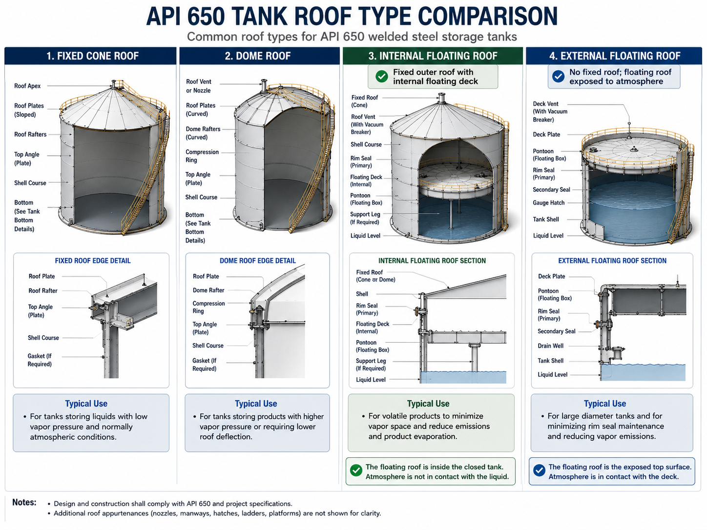
Fixed Cone Roof
A fixed cone roof slopes from the shell toward the center and may be supported by rafters, girders and columns or designed as a self-supporting roof for suitable diameters. It provides a simple enclosed configuration for diesel, fuel oil, water and liquids whose vapor-control requirements do not demand a floating roof.
The design must account for roof dead load, maintenance load, rain, snow where applicable, internal pressure, vacuum and venting behavior. Internal columns should also be reviewed for corrosion, settlement and interference with mixers, heating coils or cleaning access.
Dome Roof
A dome roof uses curved geometry to carry loads to the shell perimeter. It can reduce or eliminate internal columns depending on the design and may be used where internal obstruction must be limited.
Aluminum dome systems can reduce roof dead weight, but material compatibility, gasket selection, attachment details and the stored-product environment must be confirmed.
Internal Floating Roof
An internal floating roof moves with the liquid surface beneath a fixed outer roof. It reduces the free vapor space above volatile liquids and protects the floating assembly from direct rain, snow and wind exposure.
Selection involves deck type, seal arrangement, support legs, anti-rotation devices, roof drains where applicable, access, gauge-well penetration and minimum operating level.
External Floating Roof
An external floating roof rests directly on the liquid and rises or falls with the stored volume. It is commonly considered for large tanks containing crude oil or volatile petroleum products where vapor-space control is important.
The design needs to address primary and secondary seals, rainfall drainage, roof buoyancy, pontoon inspection, rolling ladders, wind effects and landing conditions.
Open-Top Tank
An open-top configuration may be used for selected water or process-liquid duties where exposure to rainfall, contamination and emissions is acceptable. It should not be treated as a general oil-storage configuration.
| Roof Type | Principal Benefit | Main Engineering Control |
|---|---|---|
| Fixed cone roof | Simple enclosed storage | Venting, roof loading, and internal corrosion |
| Dome roof | Clear internal space and efficient curved structure | Shell interface, material compatibility, and roof stability |
| Internal floating roof | Reduced free vapor space under a fixed roof | Seal performance, supports, and operating clearances |
| External floating roof | Direct liquid-surface coverage | Drainage, seals, buoyancy, and wind |
| Open top | Simple access for suitable nonvolatile liquids | Environmental exposure and overflow management |
API 650 Tank Bottom Configurations
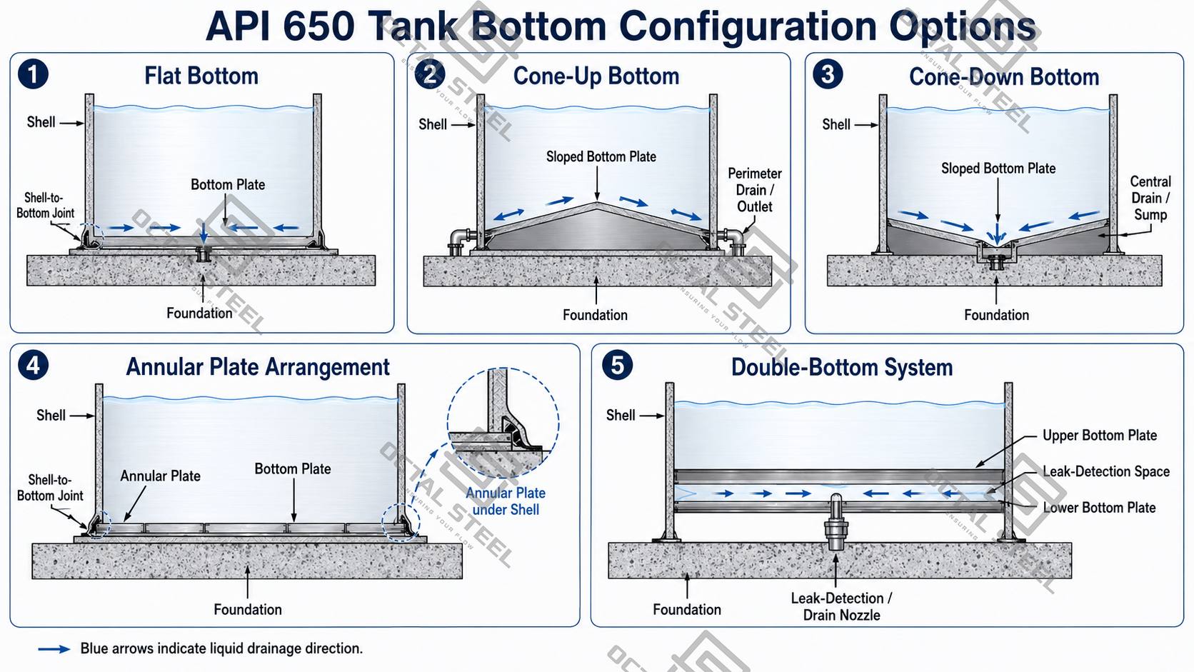
The tank bottom is selected around drainage, water settlement, corrosion control, inspection access and foundation geometry.
Flat Bottom
A nominally flat bottom is the simplest arrangement. Local slope can still be introduced to direct water and sediment toward a drain or sump.
Cone-Down Bottom
The bottom slopes toward the center. This supports central drainage and sediment collection but requires a compatible foundation profile and center-sump arrangement.
Cone-Up Bottom
The center is higher than the perimeter, directing liquid toward shell-side drains. The layout can simplify perimeter water draw-off but must coordinate with annular plates and foundation slope.
Annular Bottom Plate Arrangement
Annular plates form a defined ring beneath the shell. They are often specified where lower-shell thickness, material toughness, seismic design or shell-to-bottom stress makes a separately controlled plate ring appropriate.
Double-Bottom System
A replacement or leak-control design may include an additional bottom with an interstitial monitoring space. Drainage, leak detection, corrosion protection and foundation elevation must be designed as part of the complete system rather than added after fabrication.
API 650 Tank Pressure and Structural Loads
An API 650 tank should not be described as a conventional high-pressure vessel. Its primary load is normally the hydrostatic pressure generated by the stored liquid, with additional loads from the roof, wind, seismic action, vacuum, piping and foundation movement.
Hydrostatic pressure increases linearly with depth:
Liquid pressure = liquid density × gravitational acceleration × liquid depth
At a 20 m liquid level, water produces approximately 196 kPa gauge pressure at the bottom. A hydrocarbon with a specific gravity of 0.85 produces approximately 167 kPa at the same depth. Pressure falls toward zero at the liquid surface, which is why lower shell courses normally require greater thickness.
| Load Condition | Main Area Affected | Design Response |
|---|---|---|
| Liquid hydrostatic head | Shell, especially lower courses | Course-by-course shell thickness and material selection |
| Internal vapor pressure | Roof, roof-to-shell junction, and upper shell | Pressure checks, roof detailing, and correctly sized venting |
| Vacuum | Roof and shell | Vacuum relief, shell stability, and stiffening review |
| Wind | Shell, roof, wind girders, and foundation | Buckling, overturning, and anchorage checks |
| Seismic action | Shell, bottom, roof, anchors, and foundation | Overturning, uplift, sloshing, and nozzle flexibility review |
| Snow and rain load | Fixed roof and supporting structure | Roof plate and framing design |
| Piping loads | Nozzles and local shell zones | Nozzle reinforcement and piping flexibility |
| Settlement | Bottom, shell joint, nozzles, and roof columns | Foundation preparation, differential settlement control, and monitoring |
| Temperature change | Shell, bottom, roof, and connected piping | Thermal expansion, material stress, and movement allowance |
API’s public scope defines the normal internal-pressure basis as approximately atmospheric and notes that higher internal pressure is permitted only when additional requirements are met. It is therefore more accurate to specify the actual design pressure and vacuum than to assume that every API 650 tank has the same 2.5 psig rating.
API 650 Tank Solutions from Octal Steel
Octal Steel supports API 650 tank projects from preliminary specification review through material supply, component fabrication, inspection documentation, export packing, and field-erection coordination. Each tank package is developed around the actual storage duty, including working capacity, stored-liquid density, design pressure and vacuum, operating temperature, roof type, bottom arrangement, corrosion allowance, nozzle schedule, site loads, and installation conditions.
Available configurations include fixed-roof, internal floating-roof, external floating-roof, cone-bottom, annular-bottom, and double-bottom tanks in carbon steel, stainless steel, or duplex stainless steel where required by the service. The supply scope can include shell, bottom and roof plates, nozzles, manways, reinforcement plates, wind girders, stairways, platforms, vents, drains, heating coils, level instruments, and corrosion-protection systems.
For export projects, Octal Steel can coordinate the material and fabrication records needed to keep the tank package traceable through delivery. The document set may include material certificates, plate and heat-number maps, approved drawings, WPS/PQR records, welder qualifications, weld maps, NDE reports, dimensional inspection, bottom leak-test records, hydrostatic-test records, coating reports, packing lists, and final as-built documentation.
To prepare a technical and commercial proposal, provide the required capacity, stored product, preferred diameter and height, design temperature, pressure and vacuum, roof and bottom configuration, material grade, corrosion allowance, nozzle schedule, site wind and seismic data, inspection scope, and whether field erection or installation supervision is required.
API 650 Tank Materials
Carbon steel is the primary material route for crude oil, diesel, fuel oil, water and many general storage duties. Stainless steel and duplex stainless steel may be selected where corrosion resistance, product purity or reduced corrosion allowance changes the material economics.
Typical carbon-steel plate specifications include:
- ASTM A36
- ASTM A283
- ASTM A285
- ASTM A516
- ASTM A573
- ASTM A633
- ASTM A662
- ASTM A737
- ASTM A841
One tank does not necessarily use one plate grade throughout. Lower shell courses may use higher-strength or improved-toughness plate, while upper courses, roofs and structural members can use different permitted materials. Annular plates, nozzles and reinforcement plates also need their own thickness and toughness review.
For grade-by-grade details, material grouping and impact-test selection, refer to API 650 Tank Materials: Steel Plate Grades, Material Groups and Selection.
Corrosion Allowance, Lining and External Protection
Material strength alone does not control tank life. The corrosion system must address the stored liquid, water phase, sediment, vapor space, soil-side exposure, external atmosphere and insulation condition.
Internal Corrosion Control
Internal protection may include:
- specified corrosion allowance;
- epoxy, phenolic or other product-compatible lining;
- stainless or duplex wetted surfaces;
- water draw-off connections;
- sloped bottom and sump arrangement;
- sediment removal access;
- vapor-space coating;
- heating systems that prevent excessive product viscosity or water accumulation.
External Corrosion Control
External protection may include:
- abrasive blast cleaning;
- primer, intermediate and finish coating systems;
- UV- and weather-resistant topcoat;
- roof-edge and platform detailing that avoids trapped water;
- insulation supports and water barriers;
- corrosion-under-insulation controls;
- tank-bottom cathodic protection;
- foundation drainage.
API RP 651 addresses cathodic protection of aboveground storage tanks. API RP 652 provides guidance on selecting, applying, curing and inspecting internal tank-bottom lining systems for corrosion control.
API 650 Tank Design Process
1. Confirm Storage Duty
The design basis identifies the stored medium, density, temperature, vapor condition, water content, corrosion behavior and filling/withdrawal cycle.
2. Establish Capacity and Operating Levels
Gross capacity, working capacity, minimum operating level, maximum operating level, overfill level and required freeboard are defined separately.
3. Select Diameter and Height
Several diameter-to-height combinations are compared for shell weight, roof span, foundation size, plot area, plate availability and site erection.
4. Select Roof and Bottom Configuration
The roof is selected from the stored product’s volatility, emissions requirements, rainfall, maintenance needs and internal equipment. The bottom is selected for drainage, settlement, corrosion and leak monitoring.
5. Define Pressure, Vacuum and Temperature
Normal operating conditions and abnormal conditions are reviewed. Venting should cover filling, withdrawal, thermal breathing and emergency scenarios rather than relying only on the tank shell design.
6. Design the Shell Courses
Liquid head and allowable material stress determine the required thickness of each shell course. Corrosion allowance and permitted mill tolerance are then included in the ordered thickness.
7. Check Wind, Seismic and Stability Loads
The shell is evaluated for buckling, overturning, uplift, sloshing and anchorage. Wind girders, compression rings and anchor systems are added where required.
8. Design Bottom, Roof and Openings
Bottom plates, annular plates, shell-to-bottom joint, roof framing, nozzles, manways and reinforcement zones are developed as one coordinated arrangement.
9. Coordinate Foundation Loads
The foundation receives shell load, liquid weight, roof load and overturning reactions. Edge settlement, differential settlement and tank-bottom support must be addressed before erection.
10. Issue the Fabrication Package
The approved package normally includes calculations, general arrangement drawing, shell-course schedule, plate layouts, nozzle orientation drawings, weld details, material specifications and inspection plan.
API 650 Tank Fabrication
Plate Identification and Preparation
Steel plates are received with heat-number identification and material certificates. Cutting layouts should maintain the link between the original plate, cut components and the final tank position.
Shell plates are cut, beveled and rolled to the required radius. Bottom plates, annular plates, roof plates, reinforcement pads and structural members are prepared against approved drawings.
Prefabrication
Nozzle assemblies, manways, roof framing, wind girders, stairways, platforms, anchor chairs and other components can be prefabricated before shipment to reduce uncontrolled work at the erection site.
Dimensions that affect erection include:
- shell plate length and width;
- rolled curvature;
- edge preparation;
- nozzle neck projection;
- reinforcement-pad contour;
- stairway radius;
- wind-girder segment alignment;
- roof-framing fit-up.
Material Protection and Shipment
Prepared plates need edge protection, identification transfer and a shipment sequence that matches the erection plan. Bottom plates, first shell-course plates and annular plates should not be buried beneath later-stage components when unloaded at site.
Export documentation can connect each bundle or component mark to the packing list, drawing number and material record.
API 650 Tank Field Erection
Large API 650 welded tanks for oil storage are normally erected at the installation site because the finished diameter and height exceed road or sea-transport limits.
Foundation Survey
Before steel erection, the foundation is checked for elevation, levelness, diameter, drainage, anchor position and local high or low points. Foundation errors can be transferred directly into bottom distortion, shell out-of-roundness and nozzle misalignment.
Bottom Installation
Bottom and annular plates are positioned according to the plate layout. Welding sequence is controlled to limit distortion and shrinkage. Bottom seams are then examined before they become inaccessible.
Shell Erection
Shell courses can be erected using a conventional bottom-up method, hydraulic jacking or a crane-assisted sequence. Each course is aligned, tacked, welded and checked before the next course is completed.
Key controls include:
- circumference;
- roundness;
- verticality;
- peaking at vertical welds;
- banding at horizontal welds;
- shell-course elevation;
- joint offset;
- nozzle orientation.
Roof Installation
Roof framing or self-supporting roof sections are installed after the shell has reached the required geometry. Fixed roof plates, floating-roof components, seals, drains and access systems are fitted according to the selected configuration.
Accessories and Piping Interfaces
Manways, nozzles, vents, overflow lines, stairs, platforms, gauges, mixers, heating coils and fire-protection connections are installed against the approved orientation drawing. Connected piping should not be forced into position by using the tank nozzle as an alignment tool.
Venting and Overfill Protection
An atmospheric tank still requires a defined pressure and vacuum path. Filling displaces vapor, withdrawal draws air or gas inward, and daily temperature changes cause breathing losses. Fire exposure or abnormal heat input can create a separate emergency venting case.
API 2000 addresses venting of atmospheric and low-pressure storage tanks. API 2350 addresses overfill protection for petroleum storage tanks. These functions should be coordinated with the operating levels, fill rate, withdrawal rate, emergency scenarios and control-system philosophy.
A complete tank arrangement may include:
- normal pressure/vacuum vent;
- emergency vent;
- flame-control equipment where required by the site specification;
- independent high-level alarm;
- independent overfill protection level;
- overflow connection where permitted;
- inlet isolation or shutdown interface;
- level gauge and local indication;
- temperature measurement;
- vapor recovery connection.
The overflow opening should not be treated as the primary overfill-detection method. API documentation points to defined maximum capacity and overfill protection levels and references API 2350 for the protection system.
API 650 Tank Accessories
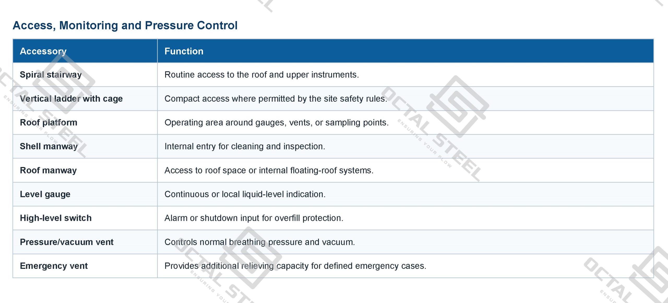
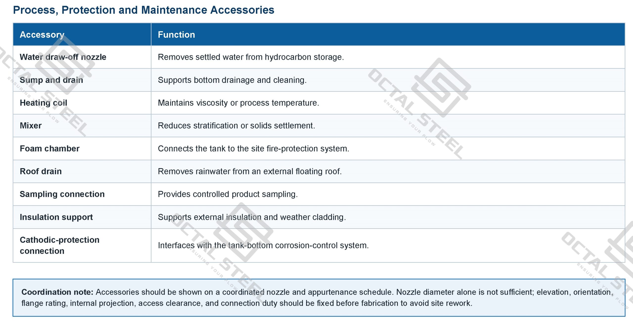
API-650-Tank-Accessories-OCTAL
Accessories should be shown on a coordinated nozzle and appurtenance schedule. A correct nozzle diameter without the correct elevation, orientation, flange rating or internal projection can still cause major site rework.
API 650 Tanks for Oil and Liquid Storage
Crude Oil Terminal Storage
A crude-oil tank may operate through repeated receipt, settling and export cycles. The product can introduce bottom sediment and water, while high throughput increases the importance of inlet arrangement, water draw-off, floating-roof seals, level control and bottom corrosion management.
Large-diameter configurations may use an external or internal floating roof depending on emissions, weather and operating requirements. Shell thickness, seismic behavior, roof drainage and foundation settlement become increasingly important as capacity grows.
Diesel and Refined Fuel Storage
Refined-product storage requires clean segregation, controlled water settlement and reliable overfill prevention. Fixed-roof or internal-floating-roof configurations may be selected according to product volatility and emissions requirements.
Internal cleanliness, nozzle dead legs, drainage, coating compatibility and dedicated transfer lines affect product quality during repeated filling and withdrawal.
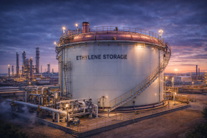
Heated Fuel Oil and Bunker Fuel Storage
Heavy fuel and bunker products can require heating coils or external heating to maintain pumpable viscosity. The design needs to consider maximum temperature, thermal cycling, insulation, circulation nozzles, coil supports and bottom drainage.
Where the maximum design temperature exceeds 93°C (200°F), the Annex M elevated-temperature route becomes relevant, up to the stated Annex limit of 260°C (500°F).
Demineralized and Treated Water Storage
Demineralized water can be aggressive toward unsuitable materials and coatings. Stainless steel, lined carbon steel or another approved material route may be selected based on water chemistry and downstream purity requirements.
The roof, vent filtration, internal surface, welding condition and contamination control can be as important as structural strength.
Wastewater and Sludge Holding
Sludge tanks need bottom geometry, drain size, mixer arrangement and cleaning access that reflect the solids content. Flat bottoms with poorly located drains can leave a large unpumpable inventory.
Corrosion allowance, lining, nozzle reinforcement and mixer-induced loads should be included in the original design rather than added after the tank is built.
Process Buffer Storage
Buffer tanks operate with frequent level changes and continuous inflow and outflow. Usable volume, surge allowance, instrument response, nozzle orientation and mixer requirements control performance.
The working capacity should be based on the process cycle, not simply the gross tank volume.
API 650 vs API 620
API 650 and API 620 both cover welded aboveground storage tanks, but they do not represent interchangeable levels of quality.
| Item | API 650 | API 620 |
|---|---|---|
| Primary duty | Atmospheric or near-atmospheric non-refrigerated liquid storage | Large welded low-pressure storage |
| Pressure basis | Approximately atmospheric; additional requirements apply where higher internal pressure is specified | Gas or vapor-space pressure up to 15 psig |
| General temperature basis | Up to 93°C (200°F) under the basic scope | Metal temperature up to 250°F under the basic scope |
| Tank form | Vertical cylindrical tank with a fully supported bottom | Large field-assembled tank with a vertical axis of revolution |
| Typical selection | Crude oil, fuel, water, and general liquid storage | Low-pressure, refrigerated, or controlled vapor-space duty |
| Main design emphasis | Hydrostatic shell design, roof, bottom, wind, seismic action, and atmospheric venting | Low-pressure containment, temperature route, and specialized tank geometry |
Use API 650 tanks where the storage duty remains close to atmospheric and non-refrigerated. Use the API 620 route where vapor-space pressure or low-temperature duty moves beyond the ordinary API 650 basis. For a detailed comparison, refer to the API 620 storage tank page.
FAQ
F1:What are API 650 tanks used for?
Q1:API 650 tanks are vertical, cylindrical, aboveground welded tanks used for non-refrigerated storage of crude oil, fuels, water, wastewater, and other liquids at approximately atmospheric pressure.
F2:What pressure can an API 650 tank withstand?
Q2:API 650 does not assign one pressure rating to every tank. The basic scope covers internal pressure approximately atmospheric; higher pressure requires additional design checks. The required positive pressure and vacuum must be stated in the tank data sheet.
F3:What is the API 650 latest edition?
Q3:The latest published version is API 650, 14th Edition, issued in August 2025. Purchase documents should identify the exact edition and any project amendments instead of stating only “latest edition.”
F4:What information is required for an API 650 tank quotation?
Q4:Provide the stored liquid, specific gravity, working capacity, tank diameter and height, design pressure and vacuum, temperature, roof and bottom type, material, corrosion allowance, nozzle schedule, site wind and seismic data, and required erection scope.