Your Responsible Supplier Partner for Oil and Gas Products.

Electric Submersible Pump
Recent Products

Rencent Articles




Electric Submersible Pump
Liquid Rate: 20–4,700 m³/d
Developed Head: Up to 3,500 m
Casing Size: 4-1/2 in to 9-5/8 in
Motor Voltage: 140–3,600 V
Temperature: 90–210°C, high-temperature options up to about 250°C
Applications: High-rate, high-water-cut, deep, deviated and offshore oil wells
Electric Submersible Pump (ESP) systems use a downhole electric motor to drive a multistage centrifugal pump and continuously lift well fluids through the production tubing. Unlike sucker-rod pumping, mechanical power is generated directly downhole rather than transmitted through a reciprocating rod string. In suitable oil wells, ESP can deliver several times to more than ten times the continuous liquid rate of a conventional sucker rod pumping system, while avoiding reciprocating rod-string limitations. This makes ESP particularly suitable for wells requiring moderate to very high liquid rates, high water handling capacity, compact surface equipment or artificial lift in deviated and offshore completions.
Octal supplies Electric Submersible Pump systems covering approximately 20–4,700 m³/d of liquid production, with developed head up to about 3,500 m. Complete ESP packages can include the multistage pump, intake or gas separator, protector, submersible motor, downhole sensor, power cable, transformer and variable-speed control system. Final configuration is matched to casing size, pump setting depth, target liquid rate, total dynamic head, fluid properties and well temperature.
How Does an Electric Submersible Pump Work?
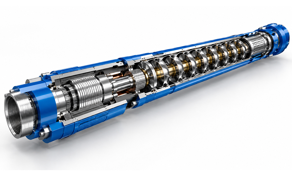
Conventional oilfield ESP uses a series of centrifugal pump stages installed above a submerged electric motor. Each stage contains a rotating impeller and a stationary diffuser.
Well fluid enters through the pump intake. The impeller accelerates the fluid outward and adds kinetic energy; the diffuser then converts part of this velocity into pressure. The same process repeats through successive stages. Instead of generating the entire lifting pressure in one pump element, an ESP builds head incrementally until the discharge pressure is sufficient to move fluid through the tubing to surface.
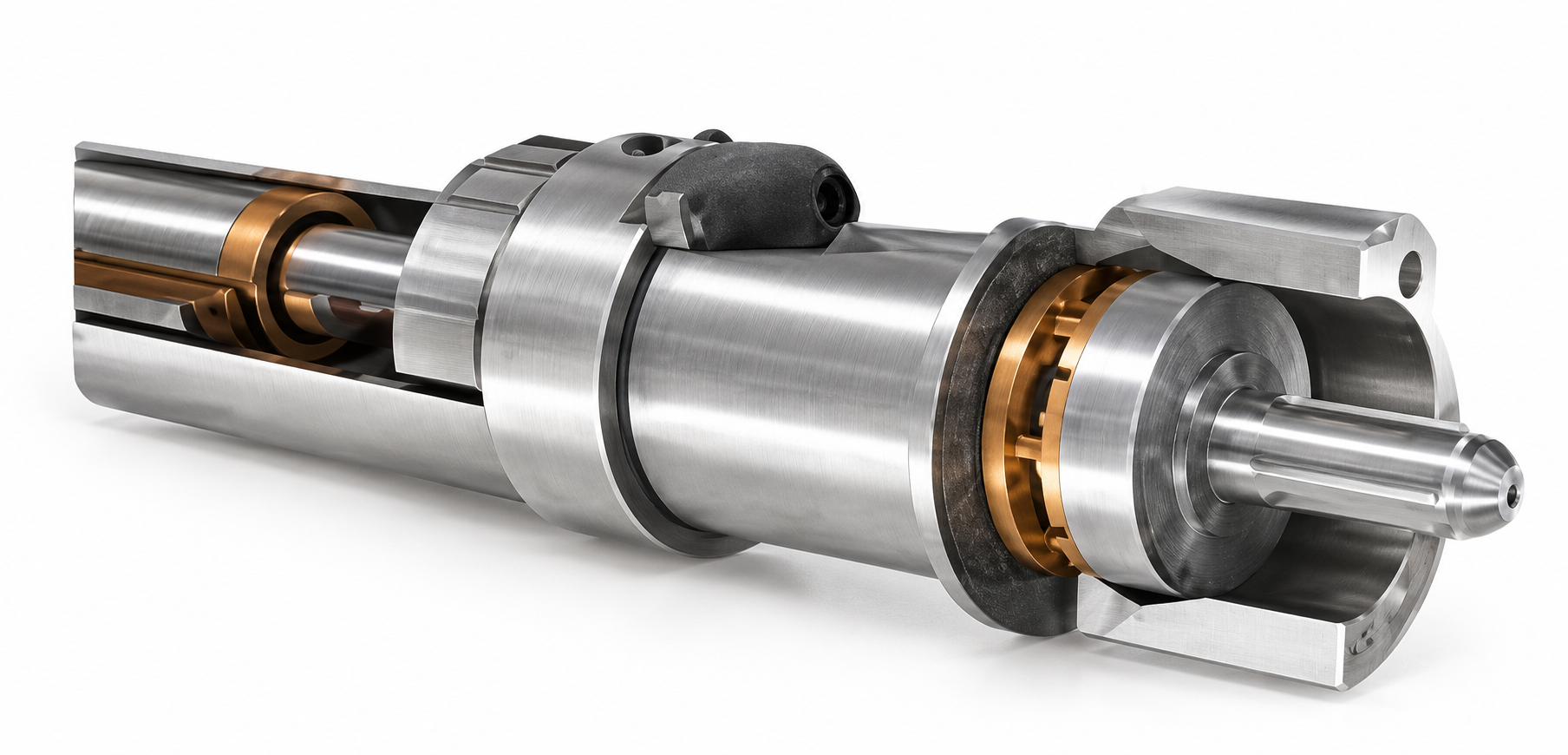
1.The required number of ESP stages is selected from the target liquid rate and total developed head.
2.Pump performance is then matched against motor power, pump efficiency and operating frequency.
3.The operating point should remain close to the Best Efficiency Point (BEP). Running too far above or below this range increases hydraulic loading, reduces efficiency and, at low flow rates, can also reduce motor cooling.
Electric Submersible Pump System Components
ESP should be treated as a complete system rather than a standalone pump.
| Component | Main Function | Engineering Focus |
|---|---|---|
| Multistage ESP Pump | Converts motor power into hydraulic head through multiple centrifugal pump stages. | Liquid rate, head per stage, pump efficiency and solids tolerance. |
| Pump Intake | Admits produced fluid into the pump and provides the inlet connection to the pump section. | Pump intake pressure, free-gas fraction and fluid entry condition. |
| Gas Separator / Gas Handler | Separates or conditions free gas before the produced fluid enters the centrifugal pump stages. | GOR, free gas at intake, gas interference and gas-lock risk. |
| Motor Protector / Seal Section | Equalizes internal motor pressure with well pressure and isolates motor oil from produced fluid. | Thrust load, seal integrity, pressure compensation and gas migration. |
| Submersible Motor | Provides downhole rotational power for the ESP pump string. | Motor power, voltage, current, operating temperature and cooling condition. |
| Downhole Sensor | Monitors operating conditions downhole and transmits data to the surface control system. | Intake pressure, discharge pressure, motor temperature, vibration and electrical leakage. |
| ESP Power Cable | Supplies three-phase electrical power from surface equipment to the downhole motor. | Voltage drop, conductor size, temperature rating, gas resistance and corrosion resistance. |
| Motor Lead Extension | Connects the main ESP power cable to the motor terminal or pothead. | Insulation integrity, temperature resistance, gas exposure and connection reliability. |
| VSD / VFD | Controls motor frequency and speed to adjust ESP production and startup conditions. | Production control, startup current, operating frequency and pump operating range. |
| Transformer | Matches the available surface power supply to the voltage required by the ESP motor system. | Voltage ratio, power rating, cable voltage loss and electrical load. |
| Junction Box / Wellhead Feedthrough | Provides the electrical transition between the surface power system and the downhole cable at the wellhead. | Pressure sealing, electrical insulation, hazardous-area safety and cable integrity. |
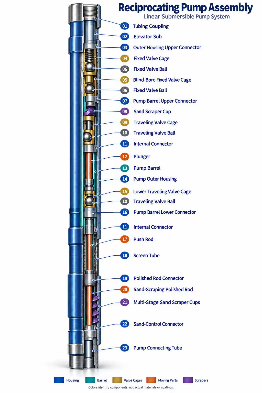
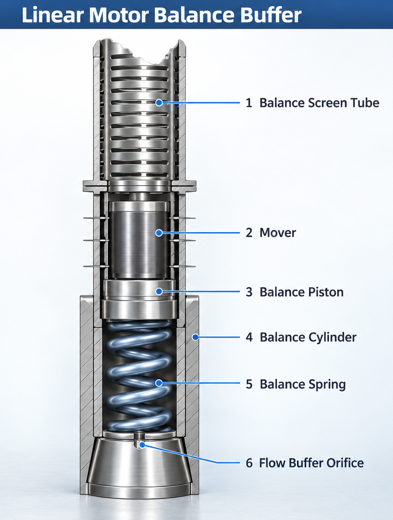
This system architecture is consistent with ISO 15551:2023, which covers tubing-deployed centrifugal ESP components including pumps, gas-handling equipment, intakes, mechanical gas separators, seal chambers, induction motors, couplings and downhole power cables.
Octal’s published ESP configuration follows the same division: surface transformer and VFD cabinet, power cable and motor-lead cable, plus the downhole pump, intake, protector, motor and sensor.
Typical ESP Performance Range
| Parameter | Typical Range | Selection Notes |
|---|---|---|
| Liquid Rate | 20–4,700 m³/d | Selected according to target total liquid production, water cut, reservoir inflow and expected production decline. |
| Developed Head | Up to approx. 3,500 m | Determined by setting depth, intake pressure, tubing friction, fluid density and required surface pressure. |
| Motor Voltage | 140–3,600 V | Matched to motor power, installation depth, cable length and allowable voltage drop. |
| Motor Current | 14–104 A | Depends on motor rating, voltage, pump load and operating frequency. |
| Motor Speed | Approx. 2,850 rpm at 50 Hz Approx. 3,420 rpm at 60 Hz |
Typical operating speed for induction-motor ESP systems; speed can be adjusted with a variable-speed drive. |
| Motor Temperature Class | 90–210°C | Motor insulation, protector, cable and downhole sensor must be selected for the same thermal environment. |
| High-Temperature Configuration | Up to approx. 250°C | Requires application-specific motor insulation, cable construction, protector materials and thermal qualification. |
These are reference envelopes, not a purchase specification. A 4,000 m³/d pump cannot automatically be applied at any depth, temperature or fluid condition. Rate, head, motor load, cable voltage drop and thermal limits must be checked as one system.
Where Electric Submersible Pumps Are Most Effective
High-Liquid-Rate Oil Wells
ESP is especially effective in wells producing several hundred to several thousand cubic metres of total liquid per day. In mature waterflood fields, oil rate may decline while total fluid remains high because water cut continues to increase, so pump selection should be based on total liquid handling rather than oil production alone.
Offshore Wells
Offshore installations benefit from the small surface footprint of ESP systems. Removing the surface pumping unit reduces mechanical equipment on deck, while power supply, VSD control and downhole monitoring can be integrated into the platform electrical system. The main concern offshore is usually intervention cost if the downhole assembly has to be pulled.
Deviated and Horizontal Wells
Without a reciprocating sucker-rod string, ESP avoids the same rod-on-tubing wear mechanism seen in rod lift. This becomes increasingly important as deviation and dogleg severity increase. Installation still has to account for casing drift, cable clearance and the bending limit of the ESP assembly.
Deep Wells
High stage counts allow ESP systems to build substantial total head. Systems with developed head around 3,500 m are available, but increasing depth also raises cable voltage loss and motor power requirements, so pump and electrical design have to be checked together.
High-Temperature and Severe-Service Wells
High-temperature, sour and sandy wells require more than a standard pump section. Motor insulation, protector seals, power cable, bearings and metallurgy may all need upgrading, especially where H₂S, CO₂, high GOR or abrasive solids are present.
Electric Submersible Pump vs Sucker Rod Pump
| Item | Electric Submersible Pump | Sucker Rod Pump |
|---|---|---|
| Power Transmission | Downhole electric motor drives the pump directly. | Surface pumping unit transmits reciprocating motion through the sucker rod string. |
| Pump Motion | Continuous rotary multistage centrifugal pumping. | Reciprocating positive-displacement pumping. |
| Typical Production Range | Moderate to very high liquid production rates. | Low to moderate liquid production rates. |
| High Water Cut | Well suited to high total liquid production in mature oil wells. | Applicable, but total liquid-handling capacity is more limited. |
| Deviated Wells | No reciprocating rod string, reducing rod-on-tubing friction and wear. | Rod and tubing contact can increase friction and wear as deviation rises. |
| Surface Footprint | Relatively compact surface equipment. | Requires a pumping unit and associated surface mechanical equipment. |
| Free Gas | May require a gas separator, gas handler or specialized intake design. | Free gas can reduce pump fillage and volumetric efficiency. |
| Sand and Solids | Abrasive solids can wear impellers, diffusers, bearings and gas-handling components. | Sand can damage downhole pump components and accelerate rod and tubing wear. |
| Very Low Production Rate | Conventional ESP may operate inefficiently below its recommended flow range. | Frequently suitable for low-rate oil wells. |
| Workover | Electrical or mechanical failure may require pulling the ESP assembly and production tubing. | Rod or downhole pump intervention depends on the completion and failure location. |
Octal notes that conventional ESP economics become less attractive below approximately 25 m³/d (150 bbl/d). However, this is not an absolute technical limit: newer low-flow ESP designs have been applied below 200 barrels of total fluid per day in specific wells.
The main advantage of ESP is therefore large and continuous lifting capacity, not a universal 20× efficiency advantage.
ESP Selection Starts With Oil Well Production Data
Electric Submersible Pump sizing begins with the production condition of the oil well rather than pump diameter alone. The main inputs are the current and target total liquid rate, oil production, water cut, gas-oil ratio, flowing bottomhole pressure and expected reservoir decline. These parameters determine whether the selected ESP can remain within its recommended operating range as the well moves from initial production to higher water cut or lower reservoir pressure.
For mature oil wells, total liquid rate can remain high even when oil production declines because produced water becomes a larger part of the well stream. This is one reason ESP systems are widely used in high-water-cut fields: the pump is selected on total produced liquid, while motor loading, gas handling and stage count are checked against the expected oil, water and free-gas conditions at the pump intake.
Total Dynamic Head
The required pump head is calculated from the pressure and depth conditions of the production system. Pump setting depth, producing fluid level, pump intake pressure, tubing size, wellhead pressure, flowline pressure, fluid density and tubing friction are combined to determine the total dynamic head that the ESP must generate. The required head is then matched with the pump series and number of centrifugal stages.
Completion and Downhole Conditions
ESP outside diameter and total assembly length must also match the oil-well completion. Casing drift, tubing size, pump setting depth, well deviation, dogleg severity and cable clearance all affect whether the system can be run safely to the planned depth. For deviated and offshore wells, these mechanical limits can be as important as pump capacity.
Completion and Casing Size
ESP system selection must match the actual oil-well casing and completion geometry. Common ESP installations are designed for casing sizes such as 4-1/2 in, 5 in, 5-1/2 in, 7 in, 8-5/8 in and 9-5/8 in, with the final pump, protector and motor outside diameter selected according to the minimum casing drift rather than nominal casing size alone. Smaller casing restricts the maximum ESP outside diameter and therefore limits motor size, pump series and achievable flow capacity, while larger casing allows higher-capacity pump sections and more powerful motors.
| Casing Size | ESP Selection Focus |
|---|---|
| 4-1/2 in | Compact pump and motor OD; limited annular clearance |
| 5 in / 5-1/2 in | Common slim ESP configurations for restricted completions |
| 7 in | Wider pump and motor selection; suitable for higher production rates |
| 8-5/8 in | Allows larger ESP assemblies and higher motor power |
| 9-5/8 in | Large-bore completion suitable for high-capacity ESP systems |
ESP Design for Gas, Solids and High-Temperature Wells
Conventional centrifugal ESP systems use a downhole rotary motor to drive a multistage centrifugal pump, making them suitable for moderate- to high-rate, high-water-cut and deep oil wells.
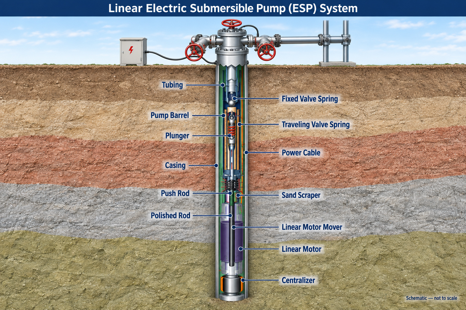
For low-rate wells, a linear-motor submersible pump provides a different rodless lifting option. It uses a permanent-magnet linear motor to drive a reciprocating plunger pump directly downhole, avoiding operation far below the recommended flow range of a conventional ESP.
Octal can match the system to production rate, casing size, setting depth, well deviation and downhole temperature. A representative offshore configuration uses a 143 mm motor OD for 9-5/8 in casing, with approximately 50 m³/d liquid rate, 1,500 m head, 60 kN thrust and 80 kW motor power. High-temperature designs can approach 150°C, with pressure qualification up to 30 MPa for 24 h depending on the equipment specification.
Conventional ESP and Linear-Motor Submersible Pump Systems
Conventional centrifugal ESP systems are designed for continuous liquid lifting at moderate to high production rates. A downhole rotary motor drives a multistage centrifugal pump, with each stage adding pressure until the produced fluid can be lifted through the tubing to surface. This configuration is particularly suitable for high-liquid-rate, high-water-cut and deep oil wells.
For low-rate oil wells, operating a conventional ESP far below its recommended flow range can reduce hydraulic efficiency and weaken motor cooling. In these conditions, a linear-motor submersible pump provides a different rodless artificial-lift option. Instead of a rotary motor and multistage centrifugal pump, the system uses a permanent-magnet linear motor to drive a reciprocating plunger pump directly downhole.
Octal can match the artificial-lift configuration to the required production range, casing size, setting depth, well deviation, fluid condition and downhole temperature. A representative linear-motor configuration for offshore oil wells uses a 143 mm motor OD for installation in 9-5/8 in casing, with design parameters around 50 m³/d liquid rate, 1,500 m developed head, 60 kN thrust and 80 kW motor power. High-temperature configurations can be designed for operating conditions approaching 150°C, while pressure-containing motor sections may require qualification testing up to 30 MPa for 24 h, depending on the approved equipment specification.
| System Type | Conventional Centrifugal ESP | Linear-Motor Submersible Pump |
|---|---|---|
| Downhole Drive | Rotary electric motor. | Permanent-magnet linear motor. |
| Pump Type | Multistage centrifugal pump. | Reciprocating plunger pump. |
| Main Operating Range | Moderate to high liquid production rates. | Low liquid production rates. |
| Main Advantage | High continuous lifting capacity for large total liquid volumes. | Rodless artificial lift for low-production oil wells. |
| Key Selection Issue | Flow range, total developed head, gas handling and motor cooling. | Stroke, thrust, pump displacement and motor temperature. |
| Typical Application | High-water-cut, deep and high-rate oil wells. | Low-rate, deviated or difficult rod-lift oil wells. |
The two systems therefore serve different production windows. Conventional ESP is selected primarily for continuous high-rate lifting, while the linear-motor system extends rodless artificial lift into lower-rate wells where a centrifugal ESP may operate too far from its optimum range.
Information Required to Select an ESP System
A useful ESP inquiry should contain enough information to perform an actual system design.
| Well / Fluid Data | Information Required |
|---|---|
| Completion | Casing size and weight, minimum casing drift, tubing size and completion restrictions. |
| Well Geometry | Measured depth (MD), true vertical depth (TVD), pump setting depth, well deviation and dogleg severity. |
| Production | Current and target total liquid rate, oil production rate, water cut and expected production decline. |
| Reservoir | Static bottomhole pressure, flowing bottomhole pressure and productivity index. |
| Fluid | Oil API gravity, water specific gravity, fluid viscosity and produced-fluid density. |
| Gas | Gas-oil ratio (GOR), bubble-point pressure and expected free-gas fraction at the pump intake. |
| Solids | Sand concentration, particle size and expected solids-production behavior. |
| Corrosion | H₂S, CO₂, chloride concentration and produced-water chemistry. |
| Temperature | Bottomhole temperature and expected motor operating environment. |
| Surface Conditions | Wellhead pressure, flowline pressure and required surface discharge condition. |
| Electrical | Available supply voltage, frequency, power source and cable length to the ESP motor. |
| Control | Fixed-speed or VSD operation, downhole monitoring and surface communication requirements. |
Only after these inputs are known should pump series, stage count, motor power, protector configuration, gas separator, cable and VSD be finalized.
FAQ
Q: What is an Electric Submersible Pump (ESP) used for in oil wells?
A: Electric Submersible Pump systems provide artificial lift when reservoir pressure cannot deliver the required production rate naturally. They are especially suitable for high-liquid-rate, high-water-cut, deep and offshore oil wells, with typical system capacities from about 20 to 4,700 m³/d.
Q: How does an Electric Submersible Pump work?
A: A downhole electric motor drives a multistage centrifugal pump. Each impeller and diffuser stage adds pressure to the produced fluid, and multiple stages build enough total head to lift the fluid through the production tubing to surface. ESP systems can develop approximately 3,500 m of head depending on the selected pump and well conditions.
Q: What are the advantages of ESP compared with a sucker rod pump?
A: ESP provides much higher continuous liquid-handling capacity and does not require a reciprocating sucker rod string. This reduces rod-on-tubing wear in deviated wells and also gives a smaller surface footprint. Sucker rod pumping, however, can remain more practical for very low-rate oil wells, so the choice depends on production rate and completion conditions.
Q: What information is required to select the correct ESP system?
A: ESP sizing normally requires casing size and drift, pump setting depth, target liquid rate, water cut, GOR, bottomhole pressure, fluid density, sand content, H₂S/CO₂, well temperature and available surface power. These data determine the pump series, stage count, motor power, gas-handling equipment, cable and VSD configuration.