Your Responsible Supplier Partner for Oil and Gas Products.

Cement Silo
Recent Products



Rencent Articles




Cement Silo
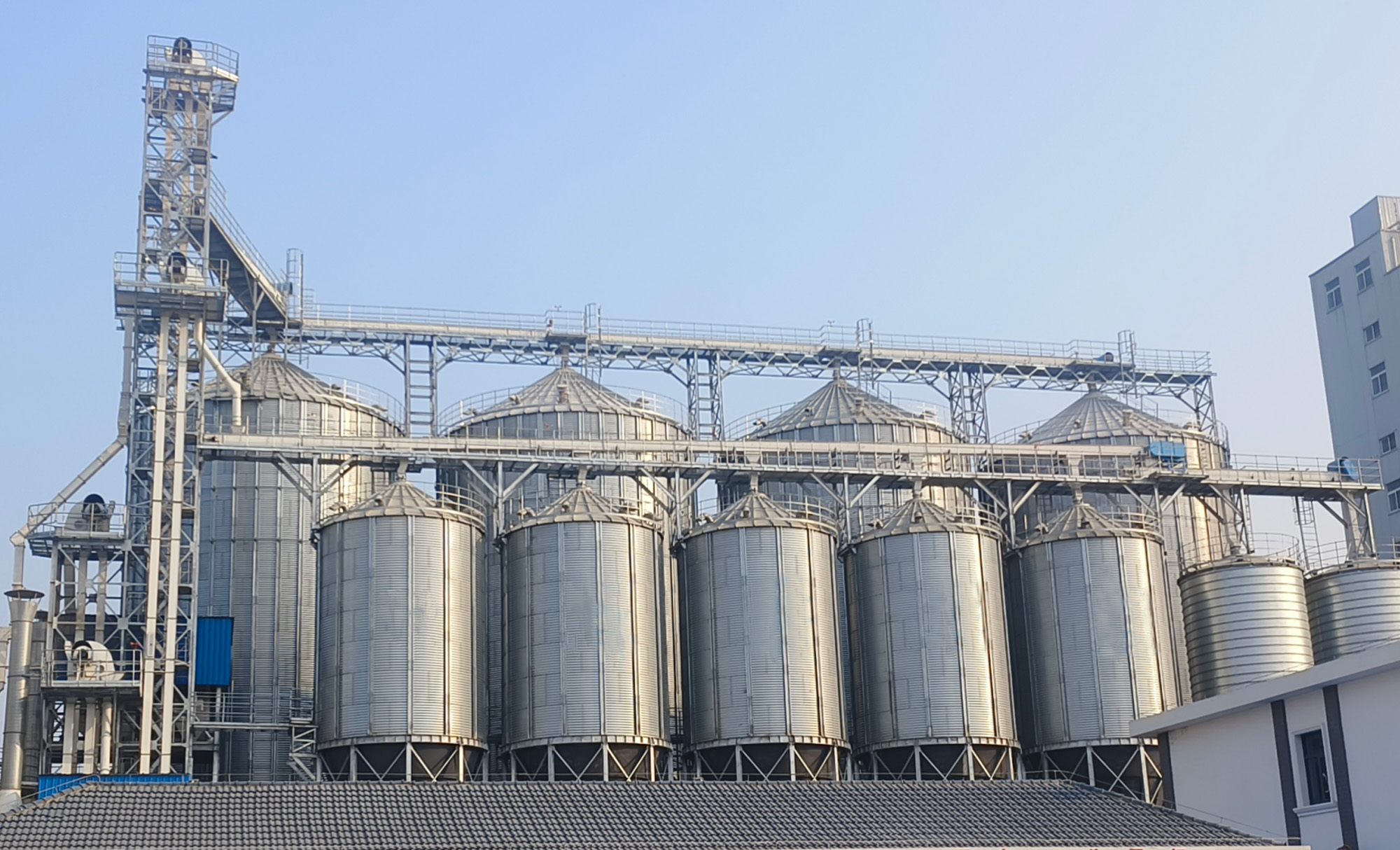
Silo Types: Spiral, bolted, welded and mobile configurations for different site conditions.
Storage Function: Enclosed storage protects dry cement from moisture, contamination and material loss.
System Integration: Compatible with bucket elevators, pneumatic conveying, dust collectors and level sensors.
Applications: Cement plants, batching plants, dry mortar lines, precast facilities and bulk terminals.
Cement Silo Types
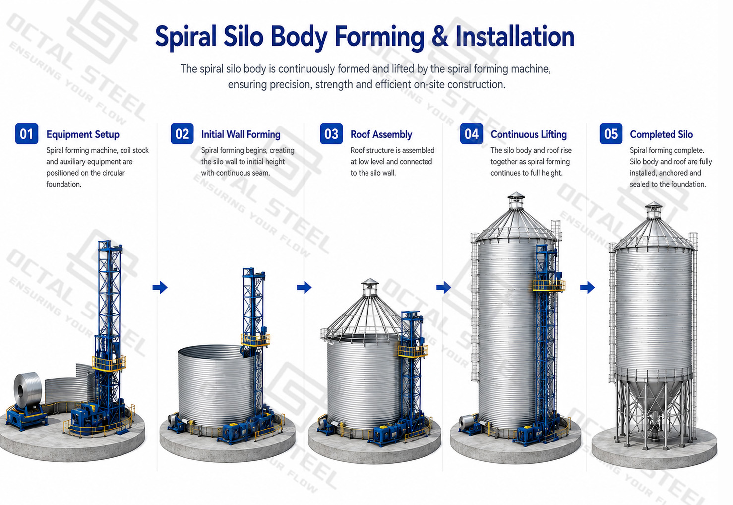
Cement silos are mainly classified by their fabrication method and installation arrangement. A spiral cement silo is continuously formed at the project site and is suitable for fixed medium- and large-capacity storage. A bolted cement silo is manufactured as prefabricated steel panels and assembled on site, which simplifies international transport and modular installation. A welded cement silo is fabricated as a complete vessel or several welded sections before delivery, reducing field assembly work. A mobile cement silo is mounted on a skid, frame or transportable chassis for temporary or relocatable operations.
| Cement Silo Type | Fabrication and Assembly Method | Main Technical Advantages | Typical Applications |
|---|---|---|---|
| Spiral Cement Silo | Steel coil is continuously formed and mechanically seamed at the project site. The silo wall rises progressively before the roof, cone, supports and auxiliary equipment are installed. |
Suitable for medium- and large-scale fixed storage; reduces completed-silo transport restrictions; supports continuous on-site construction; suitable for multi-silo layouts. |
Cement plants, bulk cement terminals, dry mortar plants and permanent industrial storage systems. |
| Bolted Cement Silo | Curved steel panels, stiffeners, roof sections and cone components are fabricated in the factory, packed for shipment and assembled with bolts and sealing materials on site. |
Easier international transport; modular construction; convenient panel replacement; suitable for containerized shipment and projects with access restrictions. |
Overseas projects, concrete batching plants, remote construction sites and modular cement storage systems. |
| Welded Cement Silo | The shell, cone and roof are welded in the factory as a complete vessel or several large transportable sections, followed by final installation on site. |
Reduced site assembly time; fewer bolted joints; factory-controlled welding and dimensional inspection; suitable for standardized small and medium storage units. |
Small and medium batching plants, precast concrete facilities and projects with suitable crane and transport access. |
| Mobile Cement Silo | The storage vessel and discharge equipment are mounted on a skid, structural frame or transportable chassis, with optional integrated filters, conveyors and controls. |
Can be relocated between projects; shorter deployment time; reduced permanent civil work; suitable for temporary or changing production locations. |
Road and bridge construction, temporary concrete plants, tunnel projects and short-term batching operations. |
A stationary cement storage silo is generally preferred where long-term operation, larger inventory and permanent conveying systems are required. Mobile or modular units are more suitable when transport flexibility and rapid deployment are more important than maximum storage volume. The construction type should therefore be selected together with the feeding, dust collection, aeration and discharge arrangement rather than as an isolated steel vessel.
Main Components and Structure of a Cement Silo
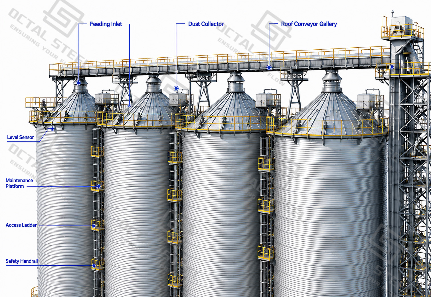
The structural body of a bulk cement storage silo must carry the combined effects of self-weight, stored-material pressure, roof-mounted equipment, wind and seismic loading, and transfer these loads safely through the support frame and anchor system to the foundation. The shell, roof, cone bottom and stiffeners therefore need to be reviewed as one continuous load path rather than as separate steel parts. At the same time, the feeding inlet, level instruments, dust collector, pressure-relief device, aeration lines and discharge valve must be positioned and sized so that filling air can escape, overfilling can be detected, cement can remain protected from moisture, and material can discharge without bridging or uncontrolled surging.
| Component Group | Main Function | Design or Inspection Focus |
|---|---|---|
| Silo Shell and Stiffeners | Contain the stored cement and maintain structural rigidity. | Steel grade, plate thickness, forming quality, reinforcement and connection condition. |
| Silo Roof and Feeding Inlet | Enclose the silo and receive cement from the conveying system. | Roof loading, weather sealing, inlet alignment and equipment penetrations. |
| Cone Bottom and Discharge Outlet | Direct cement toward downstream conveying or loading equipment. | Cone geometry, local reinforcement, outlet size and material-flow condition. |
| Supporting and Anchor Structure | Transfer silo, material and equipment loads to the foundation. | Bracing, stability, anchor position and load transfer. |
| Access and Maintenance Structures | Provide safe access for inspection and equipment servicing. | Manholes, ladders, platforms, handrails and fall protection. |
| Level, Dust and Pressure Protection | Monitor inventory, filter displaced air and control abnormal pressure. | Sensor position, alarm response, filter condition and pressure-relief operation. |
| Aeration and Flow-Control Equipment | Improve cement flow and regulate discharge. | Air distribution, blower matching, valve operation and leakage condition. |

| Feeding Equipment | Main Use | Selection Consideration |
|---|---|---|
| Pneumatic Conveying Line | Direct transfer from a bulk tanker or process source. | Airflow, conveying pressure, pipe routing and silo venting capacity. |
| Bucket Elevator | Vertical mechanical lifting of cement to the silo roof. | Required capacity, bucket speed, head-section access and equipment alignment. |
| Screw Conveyor | Controlled transfer over short horizontal or inclined distances. | Material wear, shaft sealing, conveying length and motor power requirement. |
| Air Slide Conveyor | Gravity-assisted transfer of aerated cement powder. | Air supply, installation slope, fabric condition and material flowability. |
| Roof Conveyor | Distribution of cement between multiple storage silos. | Transfer-point alignment, silo-inlet position and maintenance access. |
| Diverter Valve | Selects and directs cement to the required receiving silo. | Position feedback, internal sealing, actuator operation and control logic. |
| Feeding Chute | Connects the conveying equipment to the silo feeding inlet. | Wear condition, dust sealing, inlet alignment and unrestricted material flow. |
A typical multi-silo route is:
Receiving point → Bucket elevator → Roof conveyor → Diverter valve → Selected silo
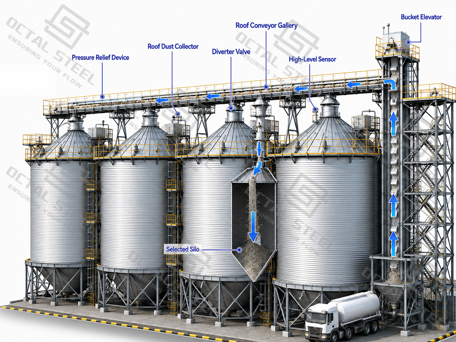
The conveying equipment should not be sized independently from the silo venting system. Rapid pneumatic filling can create excessive internal pressure when the displaced air cannot leave the silo at the required rate.
Cement Silo Dust Collection and Pressure Protection
Dust collection, level control and pressure protection are separate functions. They work together but should not be treated as interchangeable safety devices.
Roof Dust Collector
The roof dust collector filters cement particles from the displaced air produced during filling. Its airflow capacity should match the actual feeding method, particularly when cement is transferred pneumatically from a bulk tanker.
High-Level Alarm
A high-level alarm provides an independent signal when the material reaches the defined upper limit. It may be connected to the feeding sequence to stop or divert the incoming material.
Continuous-Level Sensor
A continuous-level sensor provides inventory information over a wider measuring range. It supports stock monitoring but does not eliminate the need for an independent high-level alarm.
Pressure-Relief Device
A pressure-relief device provides a controlled release path under abnormal internal pressure or vacuum conditions. It does not replace the normal silo venting and dust-collection system.
| Operating Risk | Possible Cause | Main Control Measure |
|---|---|---|
| Silo Overfilling | Failed level signal, incorrect routing or delayed shutdown. | Independent high-level alarm and feeding interlock. |
| Dust Release at the Roof | Restricted filter, damaged seals or excessive airflow. | Correct filter sizing, sealed connections and scheduled maintenance. |
| Excess Internal Pressure | Rapid pneumatic filling or a blocked vent path. | Adequate venting capacity and pressure-relief protection. |
| Vacuum During Discharge | Restricted air entry or rapid material withdrawal. | Pressure protection and operating-condition review. |
| Wrong-Silo Filling | Incorrect diverter-valve position. | Position feedback and route confirmation. |
| Filter Blockage | Inadequate cleaning or high dust loading. | Filter-cleaning system, differential-pressure monitoring and safe inspection access. |
Dust-control equipment should be accessible for filter replacement and inspection. A component that cannot be maintained safely will eventually become an operating risk.
Cement Silo Aeration and Discharge System
Cement can consolidate near the cone bottom during storage, causing arching, ratholing or intermittent discharge. A properly designed aeration system introduces controlled low-pressure air through pads or diffusers to loosen the material locally and maintain a stable flow toward the outlet.
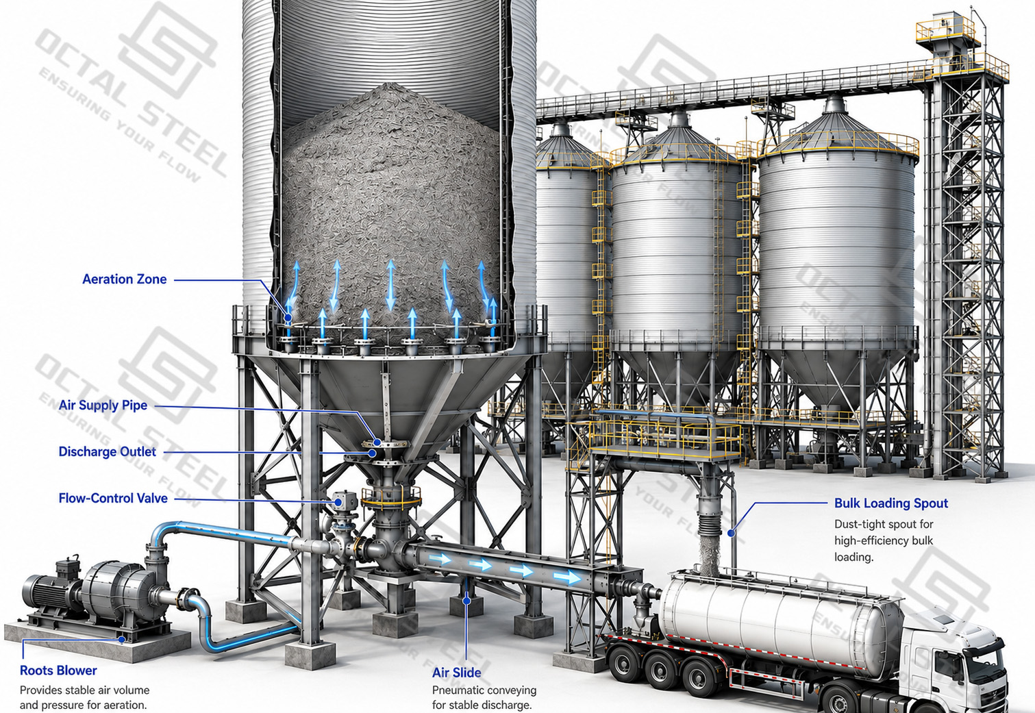
| Discharge Component | Main Function | Inspection or Operating Focus |
|---|---|---|
| Aeration Pad | Introduces air into the cement near the cone. | Coverage, permeability and attachment. |
| Roots Blower | Supplies low-pressure aeration air. | Air volume, pressure and operating temperature. |
| Air Supply Pipe | Distributes air to separate aeration zones. | Leakage, valve position and balanced air distribution. |
| Cone Bottom | Directs cement toward the discharge outlet. | Geometry, material buildup and local wear. |
| Flow-Control Valve | Regulates cement discharge. | Sealing, actuation and wear condition. |
| Screw Conveyor | Transfers cement mechanically. | Rotation direction, internal clearance and sealing. |
| Air Slide | Transfers cement using aeration and gravity. | Installation slope, air supply and fabric condition. |
| Bulk Loading Spout | Loads cement into road tankers. | Sealing, dust collection and loading position. |
Aeration performance depends on the combined control of air volume, pressure, pad layout and discharge demand. The blower, air lines, cone, valves and downstream conveyor should be checked as one system, and discharge should begin only after the receiving equipment is running and ready.
Cement Silo Quality Control and Inspection
Cement silo quality control should verify material identity, fabricated dimensions, structural connections and the performance of all auxiliary equipment before shipment or system handover. Inspection records should maintain traceability between the steel materials, silo body, roof structure, support frame, dust collection, level monitoring, aeration and discharge components.
| Inspection Area | What Should Be Checked | Record or Evidence |
|---|---|---|
| Materials and Traceability | Steel grade, plate thickness and material identity. | MTC and material list. |
| Shell, Panels and Silo Geometry | Forming quality, dimensions, diameter, verticality and alignment. | Dimensional or survey report. |
| Welded and Bolted Connections | Weld condition, applicable NDT, bolt type, alignment and tightening. | Welding, NDT or assembly records. |
| Roof, Anchors and Access Structures | Roof supports, sealed penetrations, anchor position, ladders, platforms and handrails. | Fabrication and installation inspection. |
| Dust, Level and Pressure Protection | Filter condition, sensor response, alarm position and pressure-relief movement. | Functional and instrument test records. |
| Aeration and Discharge Equipment | Air distribution, leakage, valve movement and discharge direction. | Functional-test record. |
| Final Release Documents | Material records, inspection results and component identification. | Inspection dossier and release checklist. |
NDT and third-party inspection are applied when required by the applicable standard, project specification or approved inspection plan. Final release should confirm that the structural components, auxiliary equipment and inspection records correspond to the same supplied silo system.
Cement Silo Applications
Cement Plant Storage and Dispatch
A cement plant may use silos between grinding, blending, packing and bulk dispatch. The silo provides controlled inventory while allowing cement to be released to a packing line or tanker-loading station.
Concrete Batching Plant
A bulk cement storage silo supplies cement to weighing and mixing equipment. Stable discharge is important because interrupted cement flow can delay batching cycles and affect production continuity.
Dry Mortar Production
Separate silos can store cement and other approved powdered binders before dosing. Material identity and routing must be controlled to prevent the wrong powder from entering the selected weighing line.
Precast Concrete Production
The silo supports repeated batch production for precast beams, panels, pipes or structural components. Consistent feeding to the batching system reduces interruptions between production cycles.
Bulk Cement Terminal
A terminal may receive cement by tanker, ship-unloading system or upstream conveyor. Multiple silos provide buffer storage before regional distribution, packing or bulk loading.
Temporary Construction Site
Mobile or modular silos can support road, bridge, tunnel and temporary concrete works. Transport dimensions, foundation preparation and relocation requirements become more important than they are in permanent plant installations.
FAQ