Your Responsible Supplier Partner for Oil and Gas Products.

API Spec 11B Sucker Rod
Recent Products

Rencent Articles

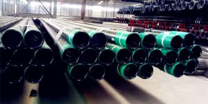

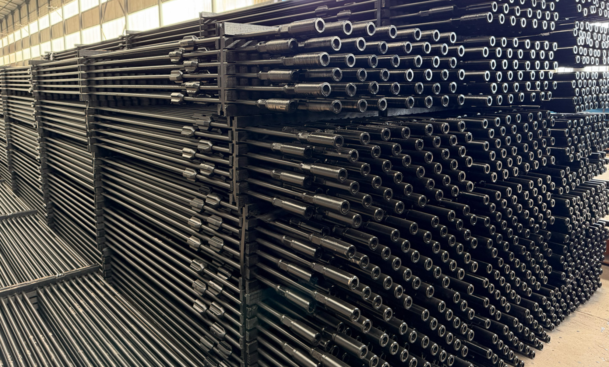
API Spec 11B Sucker Rod
Rod Body Sizes: 5/8”, 3/4”, 7/8”, 1”, 1-1/8”
Standard: API Spec 11B
Grades / Material Classes: C, K, D-Family, High-Strength Grades
Standard Lengths: 25 ft, 30 ft
End Type: Forged ends with shouldered pin connections
Connection: API sucker rod pin with matched coupling
Coupling Options: Full-size, Slim-hole, Class T, Spray Metal (SM)
Application: Rod-lift systems for transmitting reciprocating load to downhole pumps
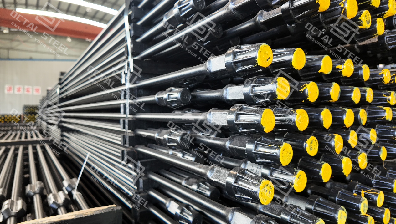
API 11B steel sucker rods in multiple sizes and material grades.
Designed for cyclic rod-string loading with forged ends, API pin connections and matched couplings.
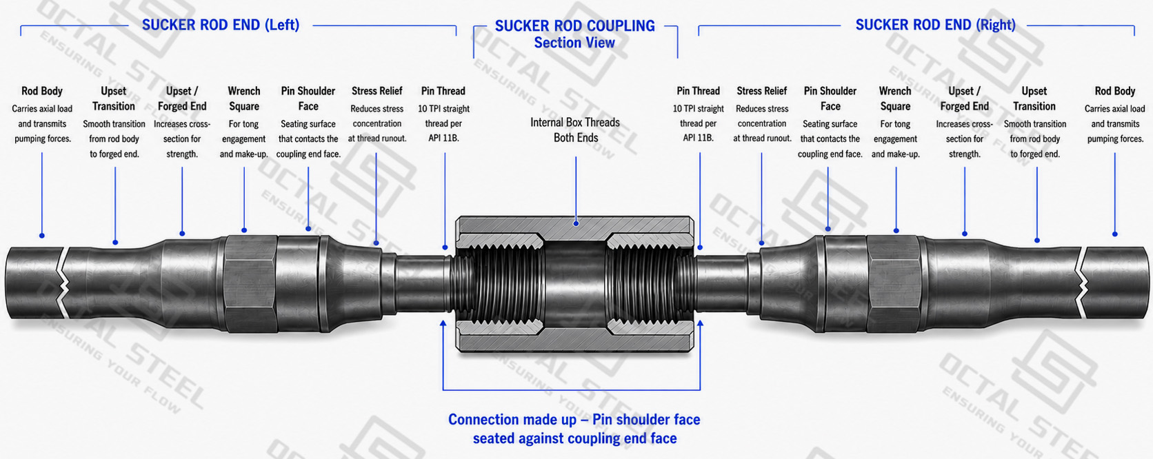
API 11B sucker rod transmit the reciprocating motion and axial load from the surface pumping unit through the rod string to the downhole pump. A steel sucker rod consists of a heat-treated rod body with forged ends, wrench squares, shouldered pin connections and matched couplings. Standard rod-body sizes commonly range from 5/8 in. to 1-1/8 in., with 25 ft and 30 ft nominal rod lengths. Rod diameter, material grade and coupling configuration must be selected together because cyclic stress, corrosion, well deviation and rod-to-tubing contact affect different parts of the string.
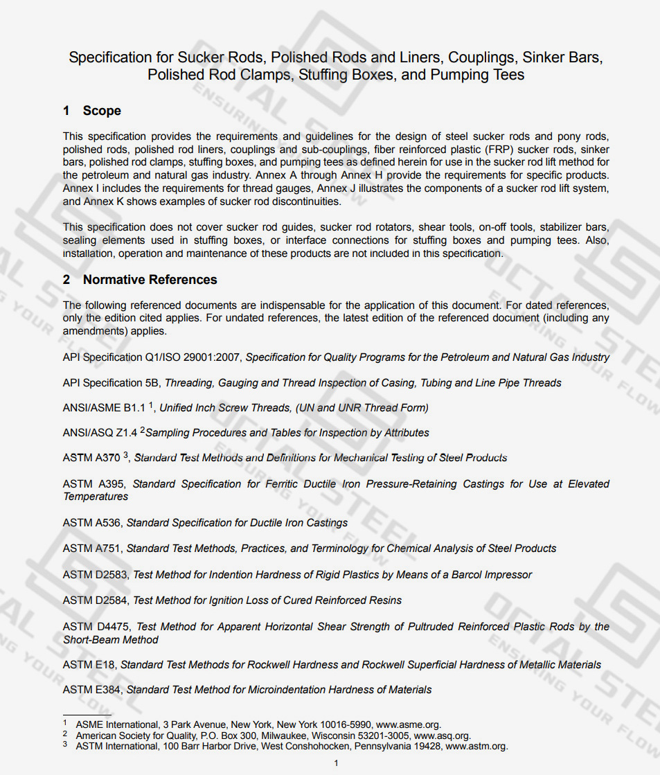
API 11B Sucker Rod Standards
| Standard | Application to Sucker Rods |
|---|---|
| API Spec 11B, 28th Edition + Addendum 1 | Steel sucker rods and pony rods, rod-end connections, couplings, dimensions, material classes, testing, marking, gauging and related rod-lift products |
| API RP 11BR | Care, handling and field practices for sucker rods |
| ISO 10428:1993 | International dimensional, mechanical-property and gauging reference for sucker rods and related products |
| Approved Manufacturer Specification | Material chemistry, heat-treatment route and special high-strength or corrosion-service rod requirements |
These references work at different levels. API Spec 11B defines the primary requirements for sucker rods, rod-end connections, couplings, dimensions, testing and marking, while API RP 11BR addresses handling and field practice. ISO 10428 provides an international dimensional and gauging reference. Project or manufacturer specifications may add material, heat-treatment or special-service requirements, but these should be stated separately from the applicable API acceptance criteria.
API 11B Sucker Rod Specifications
| Specification Item | Available Range or Requirement |
|---|---|
| Product Standard | API Spec 11B |
| Product Type | Steel sucker rod / pony rod |
| Standard Rod-Body OD | 5/8, 3/4, 7/8, 1 and 1-1/8 in. |
| Standard Rod Length | 25 ft or 30 ft nominal |
| Pony Rods | Short lengths selected to adjust total string length |
| Rod-End Connection | API shouldered sucker-rod pin |
| Coupling Configuration | Full-size or slim-hole, with applicable Class T / SM or project-specified configuration |
| Rod Grades | C, K and D-family grades; high-strength and special-service grades available where specified |
| Optional Equipment | Pony rods, sinker bars, polished rods, rod guides and other project-specific rod-string components |
| Documentation | Material certificate, mechanical-test report, dimensional/thread inspection and lot traceability |
Standard API 11B steel sucker rod sizes range from 5/8 in. to 1-1/8 in., covering the common rod-body diameters used in conventional rod-lift systems. Larger diameters may be supplied for special applications, but they should be treated as project-specific configurations and confirmed against the applicable manufacturing specification before ordering.
Sucker Rod Sizes and Connection Dimensions
The nominal rod diameter identifies only the rod body. The forged end is larger and contains the wrench square, pin shoulder and threaded connection that transfers load through the coupling.
| Nominal Rod Size | Rod Body OD | Nominal Pin Thread | Pin Shoulder OD |
|---|---|---|---|
| 5/8 in. | 15.88 mm | 15/16 in. | 1.250 in. / 31.75 mm |
| 3/4 in. | 19.05 mm | 1-1/16 in. | 1.500 in. / 38.10 mm |
| 7/8 in. | 22.23 mm | 1-3/16 in. | 1.625 in. / 41.28 mm |
| 1 in. | 25.40 mm | 1-3/8 in. | 2.000 in. / 50.80 mm |
| 1-1/8 in. | 28.58 mm | 1-9/16 in. | 2.250 in. / 57.15 mm |
The dimensions above provide a practical reference for API 11B sucker rod size and connection selection. Standard sucker-rod pins use a 10-thread-per-inch shouldered connection, while the final thread and gauge dimensions should follow the applicable API 11B requirements and approved manufacturing data.
For replacement rods, matching the nominal size alone is not enough. A 7/8 in. sucker rod, for example, should also be checked for grade, rod length, pin dimensions, coupling type and compatibility with the existing rod string before the replacement is confirmed.
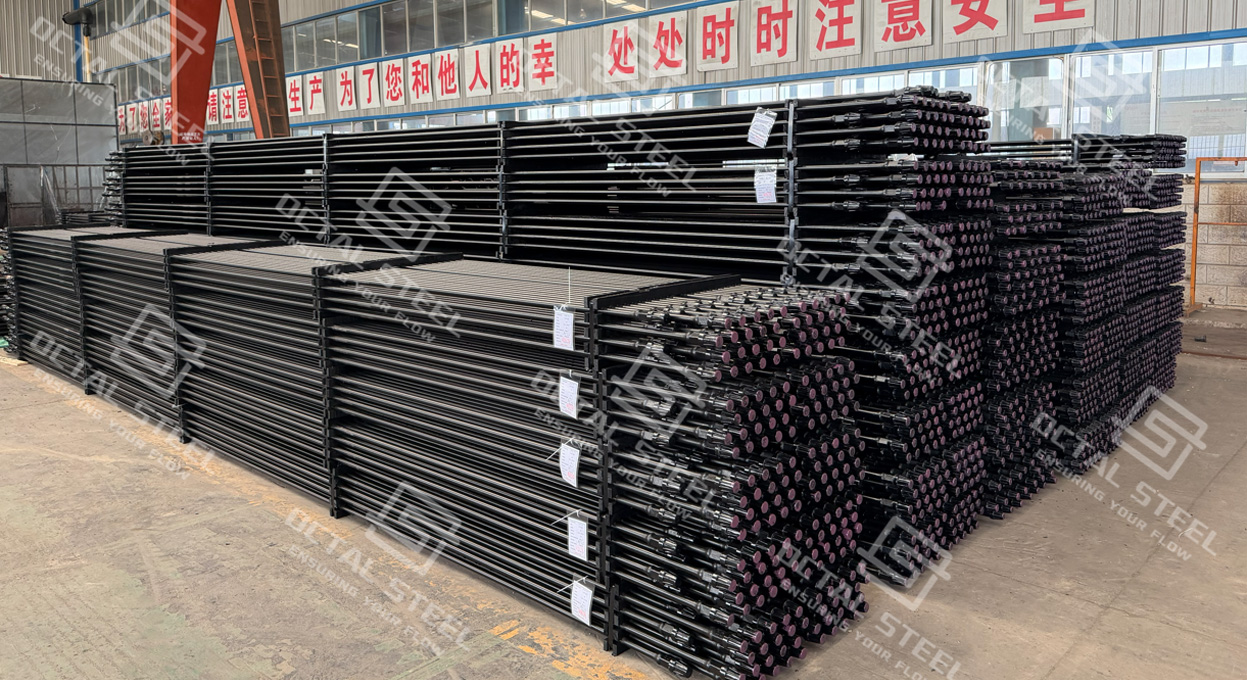
API 11B Sucker Rod Grades and Mechanical Properties
The commercial names C, K and D remain widely recognized, but current API-aligned product literature also distinguishes material classes within the D and high-strength families, such as DC, DA, DS, HA, HS and HY. These designations matter because two rods with similar tensile strength can use different steel chemistry and heat-treatment routes.
| Grade / Material Class | Minimum Yield Strength | Tensile Strength | General Position |
|---|---|---|---|
| C Carbon | 60 ksi / 414 MPa | 90–115 ksi / 621–793 MPa | Standard-strength carbon-steel rod |
| K Alloy | 60 ksi / 414 MPa | 90–115 ksi / 621–793 MPa | Standard-strength alloy-steel route |
| DC / DA / DS D-Family | 85 ksi / 586 MPa | 115–140 ksi / 793–965 MPa | Higher-load rod strings |
| HA / HS High Strength | About 115 ksi / 793 MPa minimum depending on class | Typically 140–155 ksi / 965–1069 MPa | High-stress and fatigue-sensitive service |
| HY | Case-hardened design; acceptance differs from conventional through-section grades | High-strength class | Very high-load applications subject to qualified material specification |
Current API-compliant public data list C and K at 60 ksi minimum yield and 90–115 ksi tensile, while D-family carbon, alloy and special grades are commonly specified at 85 ksi minimum yield and 115–140 ksi tensile. High-strength sucker rods should be specified by their exact material class or approved manufacturer grade, because strength level alone does not define the steel chemistry, heat treatment or service limits.
Rod grade should be selected from the actual operating conditions rather than well depth alone. Rod-string stress, pump load, stroke length and rate, fluid environment, well deviation and fatigue exposure all influence whether Grade C, K, D or a higher-strength rod is appropriate.
Grade C
Grade C provides a standard-strength carbon-steel option for light-to-moderate rod-loading conditions. Current commercial API-grade products typically use carbon-manganese steel routes and are positioned for noncorrosive or effectively inhibited service.
Grade K
Grade K uses an alloy-steel route while retaining a strength range similar to C. It should not automatically be described as a universal “corrosion-resistant” or “sour-service” grade. Actual corrosion performance depends on steel chemistry, hardness, inhibition, H₂S/CO₂ conditions and cyclic stress.
D-Family Rods
D-family rods provide higher pipe-body—or more accurately, rod-body—strength, typically 115–140 ksi tensile strength. Current material classifications distinguish carbon, alloy and special-alloy routes, allowing the selected chemistry and heat treatment to be matched more closely to load and environmental conditions. Grade D covers more than one material route, so the exact API material class should be confirmed together with the required mechanical properties and service conditions.
Sucker Rod Couplings and Connection Selection
The coupling is part of the load-carrying connection between adjacent rods, so its OD, thread, material class and fit with the rod pin should be confirmed together with the sucker rod. This becomes especially important in deviated wells and replacement strings, where tubing clearance, existing component wear and connection compatibility can affect the final configuration.
Typical full-size coupling outside diameters are:
| Rod Size | Full-Size Coupling OD |
|---|---|
| 5/8 in. | 1.500 in. / 38.1 mm |
| 3/4 in. | 1.625 in. / 41.3 mm |
| 7/8 in. | 1.812 in. / 46.0 mm |
| 1 in. | 2.187 in. / 55.6 mm |
| 1-1/8 in. | 2.375 in. / 60.3 mm |
A full-size coupling provides the standard connection envelope, while a slim-hole coupling provides additional clearance where coupling OD is restricted by the tubing or well geometry. The smaller OD should not be selected on clearance alone; connection strength, rod loading, tubing ID and expected rod-to-tubing contact still need to be considered. Class T and Spray Metal (SM) couplings can also be specified according to the required wear and service conditions.
Matching New Rods with Existing Couplings
Replacement work requires more attention than a new, uniform rod string. API 11B 28th Edition revised the pin-and-coupling geometry to address a dimensional interference condition, which means new-edition and legacy components should not be assumed to interchange simply because the nominal rod size is the same.For legacy rod-end and coupling dimensions, refer to the API Spec 11B 27th Edition reference PDF.
For example, an older producing well may require additional 7/8 in. Grade D sucker rods while the existing couplings are intended to remain in service. Before the replacement rods are released, the existing pin/coupling dimensions, API edition, coupling type, thread condition and gauge compatibility should be checked. If the old couplings show thread damage, shoulder wear or uncertain dimensional history, replacing them together with the new rods is generally a more controlled approach than relying on nominal size alone.
For a complete replacement assembly, the practical matching sequence is:
Rod size → material grade → pin dimensions → coupling size/type → thread and gauge compatibility → existing string condition
Sucker Rod String Size and Taper Selection
A sucker rod string often carries its highest axial load near the surface because the upper rods support the weight of the rod sections below together with the dynamic pump load. Using one large rod diameter through the entire well can add unnecessary string weight, so deeper rod-lift installations are often designed with a tapered rod string.
A representative configuration may be:
1 in. upper section → 7/8 in. middle section → 3/4 in. lower section
In this arrangement, the 1 in. rods are positioned in the upper section where tensile loading is highest, while the lighter 3/4 in. rods reduce suspended mass closer to the pump. The 7/8 in. section provides the transition between them. This is an example of the design principle rather than a fixed API configuration—the actual taper lengths must be calculated for the individual well.
For example, increasing the pump diameter or lowering the producing fluid level increases the load carried by the rod string. Increasing stroke length or strokes per minute can also change dynamic loading and fatigue exposure, while deviation introduces additional rod-to-tubing contact and friction. The final design should therefore check the peak and minimum rod loads, stress range and fatigue margin in each taper section, together with pump setting depth, fluid density, rod grade and corrosion conditions.
A rod string that is suitable for one operating program may need to be rechecked after a change in pump size, producing fluid level, stroke program or well condition. Rod diameter should therefore follow the calculated load distribution rather than a fixed rule based on well depth alone.
For engineering and procurement reference, download the guide covering sucker rod sizes, grade selection, tapered rod-string configuration, pin and coupling compatibility, and manufacturing inspection points:
Download:API 11B Sucker Rod Selection Guide
API 11B Sucker Rod Applications
Conventional Beam-Pumping Wells
In a conventional beam-pumping system, the surface unit repeatedly raises and lowers the polished rod, driving the coupled sucker-rod string and downhole pump. Every stroke changes the axial load in the rod string, so the design must consider both peak load and stress range rather than only ultimate tensile strength.
A 7/8 in. D-family rod, for example, may have more than enough static tensile strength for a particular well, but a high stroke rate combined with a large pump and many operating cycles can make fatigue the controlling issue.
Deviated Rod-Lift Wells
Well deviation changes the problem from pure axial loading to combined axial load and side contact.
At a dogleg, rod couplings or the rod body may repeatedly rub against the tubing. A larger full-size coupling can reduce available tubing clearance, while a slim-hole coupling may provide more geometric clearance. Rod guides may also be required where calculated side loading indicates persistent contact.
For this reason, a deviated well should not be upgraded to a stronger rod grade without also reviewing coupling OD, tubing ID, deviation profile and expected contact points.
High Pump-Load Wells
A larger pump diameter, deeper pump setting or higher fluid load increases the axial force carried by the rod string. In these conditions, a standard C or K configuration may no longer provide the required stress margin, and a D-family or high-strength rod may become appropriate.
The grade change should follow the calculated string loads rather than well depth alone. Higher-strength rod material also does not eliminate fatigue at the forged transition or connection.
Corrosive Production Environments
Produced water, chlorides, CO₂ and H₂S can accelerate pitting and corrosion-fatigue damage. A material described as “corrosion resistant” still requires the fluid environment, inhibition program, operating stress and material hardness to be reviewed together.
Current rod manufacturers explicitly separate well load from well corrosivity when recommending rod grades, because corrosion behavior depends on multiple downhole variables rather than one chemical constituent.
Replacement Rods for an Existing String
Replacement purchasing is one of the most specification-sensitive applications.
Consider an existing tally showing:
7/8 in. Grade D — 25 ft rods — full-size couplings
Before adding new rods, the purchaser should confirm:
• current material class or legacy grade designation;
• connection dimensions and API edition;
• coupling OD and grade;
• existing pin and coupling wear;
• rod length;
• surface condition and remaining serviceability of the old string.
Matching only “7/8 in. Grade D” may produce a rod with the correct body size but an unsuitable connection or coupling combination.
Sucker Rod Manufacturing and Inspection Control
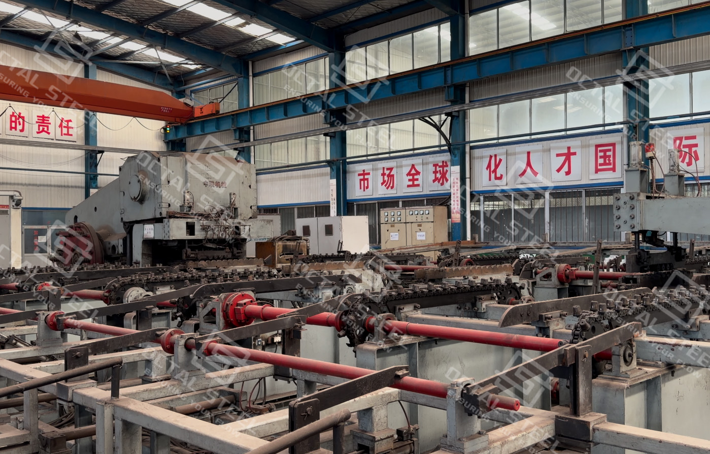
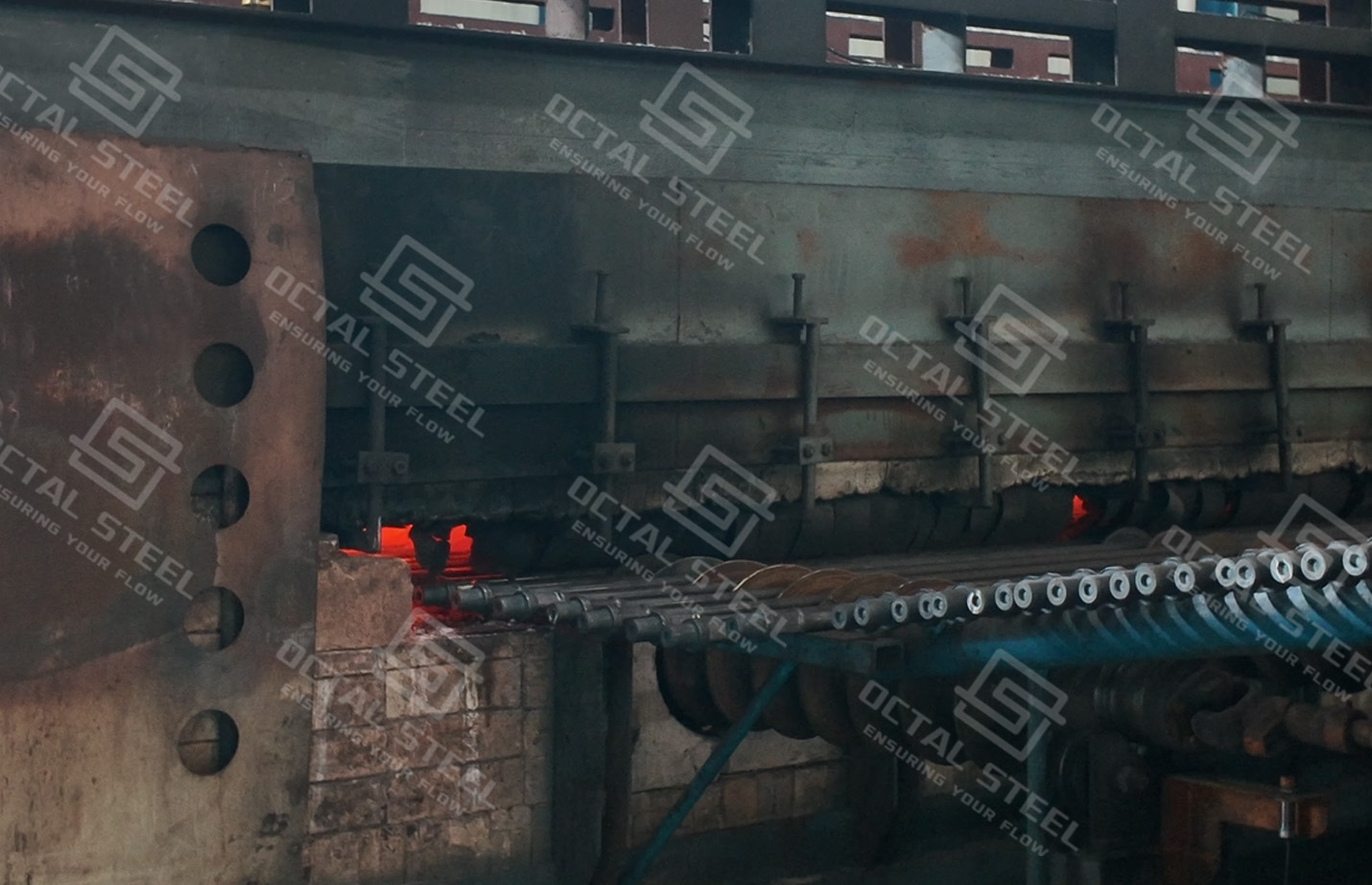
API 11B sucker rod manufacturing begins with identified steel bar and continues through end forging, heat treatment, rod-body finishing, pin machining and final inspection. End forging forms the enlarged rod end, wrench square and transition profile, while heat treatment establishes the required mechanical properties for the specified material class. The finished pin and shoulder are then machined and gauged to ensure correct fit with the selected coupling.
Inspection follows the same production route. The forged transition, rod straightness, pin thread, shoulder geometry and coupling fit receive particular attention because these areas repeatedly carry cyclic load during pumping service.
| Manufacturing Stage | Production and Inspection Control | Release Evidence |
|---|---|---|
| Steel Bar Preparation | Heat identity, chemistry, bar diameter and initial surface condition | Material certificate / heat record |
| End Forging | Rod ends are forged to form the pin section, wrench square and transition; alignment and dimensions are checked | Forging and dimensional record |
| Heat Treatment | Mechanical properties are established according to the specified rod material class | Heat-treatment and mechanical-test report |
| Rod-Body Finishing | Body diameter, straightness and surface condition are verified | Dimensional inspection |
| Pin and Shoulder Machining | Thread form, dimensions, shoulder geometry and gauge results are checked | Thread-gauging record |
| Coupling Matching | Coupling size, class, thread condition and fit with the rod pin are confirmed | Coupling inspection record |
| Final Rod Inspection | Overall length, marking, thread protection and production-lot identity are verified before packing | Final inspection and packing record |
The forged transition and pin connection are particularly important because changes in section geometry coincide with repeated cyclic loading. Their dimensional accuracy and surface condition therefore need to be controlled together with the rod-body mechanical properties.
Why Choose Octal Sucker Rods
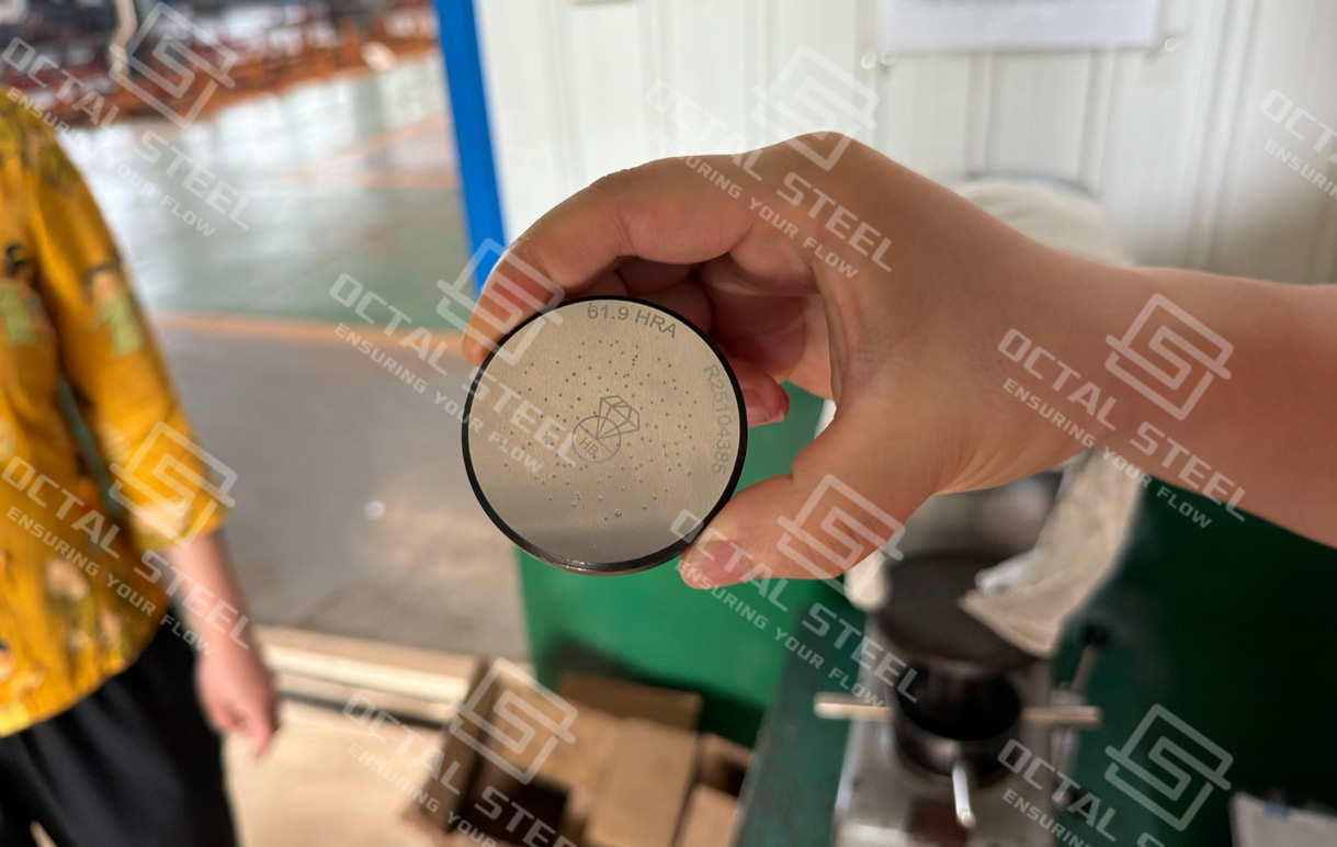
Octal focuses on the details that usually determine whether a sucker rod order works smoothly in the field. For each order, the rod size, material grade, rod length, pin configuration, coupling type and applicable API edition are reviewed together rather than treated as separate items. For replacement projects, existing rod tallies, coupling dimensions and connection details can be checked before production to reduce the risk of mismatched rods and couplings.For the broader product range, available rod types and material options, see the Octal Steel sucker rod product page.
Each production lot remains linked to its material heat, heat-treatment record, mechanical-test results, thread inspection and bundle identification. The same information is carried through the final inspection and shipment documents, giving the customer a clear record for receiving inspection, warehouse control and future replacement of individual rods.
FAQ
Q1: How should buyers compare quotations for API 11B sucker rods?
A1: Compare the same API edition, rod size, material class, length, coupling type, connection configuration, surface treatment and inspection scope. Two quotations labeled “7/8 in. Grade D” may still represent different finished rod-and-coupling configurations.
Q2: Does API 11B compliance automatically mean the sucker rods carry the API Monogram?
A2: No. The API Monogram can only be applied by an API-licensed facility to products within its licensed scope. If Monogram marking is required, it should be stated in the purchase specification and the manufacturer’s current license scope should be verified.
Q3: Should API sucker rod connections be made up by torque alone?
A3: No. Current API RP 11BR guidance includes sucker-rod joint makeup using circumferential displacement, which provides a more direct control of connection preload than torque alone. The applicable displacement value depends on rod size, grade and connection condition.
Q4: Can used sucker rods and couplings be accepted from the original material certificate?
A4: No. The original certificate does not show current fatigue damage, corrosion, wear or thread condition. API RP 11BR:2008 (R2025) includes visual, electromagnetic, pin-end and coupling inspection provisions for used sucker rods before they are returned to service.
Q5: Can the tensile strength of a sucker rod be used as its allowable operating load?
A5: No. Tensile strength is a material property, while allowable rod-string loading depends on the maximum and minimum cyclic stress, rod diameter, grade, corrosion environment and operating conditions. API RP 11BR addresses allowable sucker-rod stress using the operating stress range rather than tensile strength alone.