Your Responsible Supplier Partner for Oil and Gas Products.

Industrial Cables
Recent Products
Rencent Articles


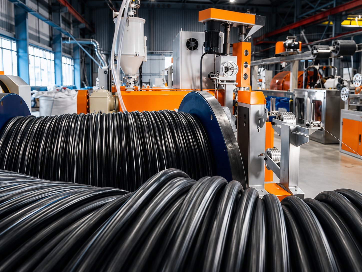
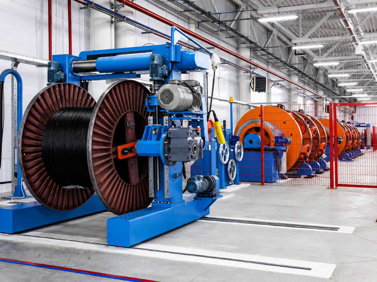
Industrial Cables
Types: Power, control, instrumentation, VFD/motor, data and flexible cables
Conductors: Copper or aluminum
Insulation: PVC, XLPE or EPR
Protection: Screened, armored, LSZH and fire-performance options
Applications: Switchgear, MCC, VFD, motors, PLC and industrial networks
Selection: Voltage, current, installation, movement and environment
Industrial cables are electrical conductors designed to transmit power, operating commands, measurement signals and digital data in factories, processing plants, substations, warehouses and automated production systems. They are commonly constructed with copper or aluminum conductors, PVC, XLPE, EPR or project-specified insulation, and outer sheaths made from PVC, PE, LSZH, PUR, TPU or other compounds selected for the installation environment.
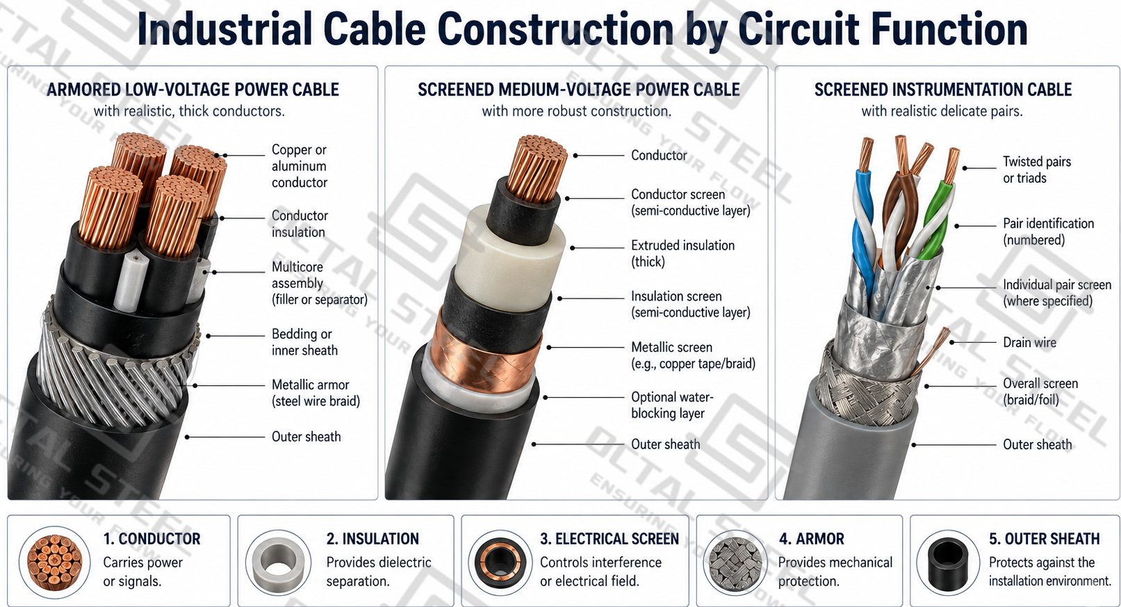
Depending on the circuit duty, an industrial cable may also contain conductor screens, twisted pairs or triads, individual or overall electrical screens, drain wires, water-blocking layers, metallic armor or fire-resistant barriers. These components work as one coordinated construction because changing the insulation, screen, armor or sheath can affect the finished diameter, electrical performance, flexibility, bending radius, gland size and termination method.
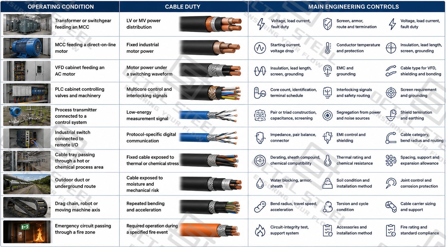
Industrial cables connect transformers, switchgear, motor-control centres, variable-frequency drives, motors, PLC cabinets, field instruments, sensors, remote I/O and industrial communication equipment. The main supply categories include low-voltage and medium-voltage power cables, multicore control cables, screened instrumentation cables, VFD motor cables, industrial Ethernet and BUS cables, and flexible cables for moving machinery.
Octal supplies industrial cables according to approved cable schedules, project datasheets and applicable standards. The supply scope can coordinate conductor material and size, insulation, screening, armor, sheath compound, movement duty, fire-performance requirements, cable lengths, drum allocation, marking, inspection records and packing documents.
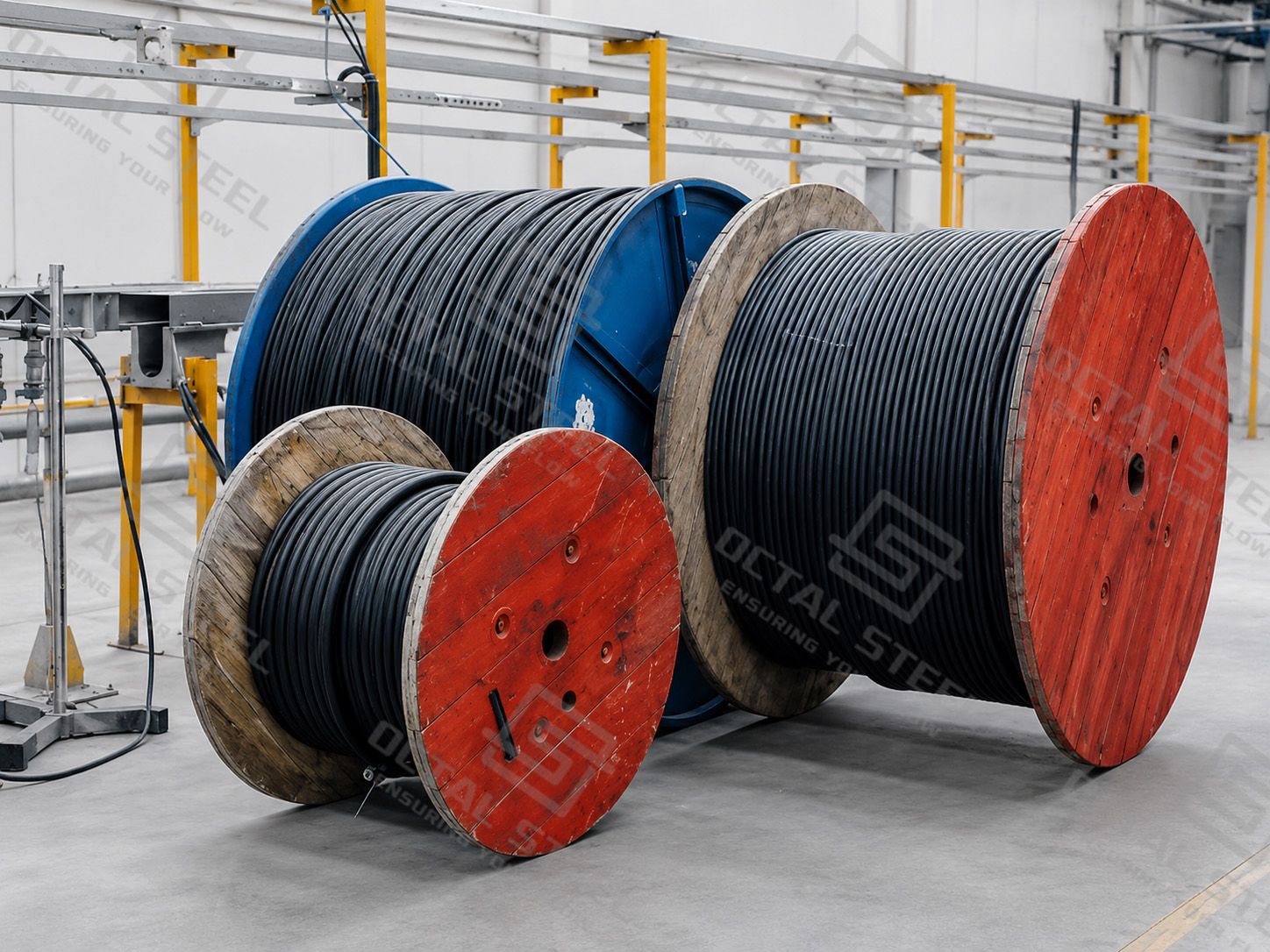
Key Technical Data at a Glance
They are provided for preliminary comparison and must not be treated as one universal Octal specification. Final values depend on the selected cable construction, applicable standard and approved project datasheet.
| Representative Cable Construction | Rated Voltage | Test Voltage | Insulation Resistance | Temperature Reference | Minimum Bending Radius | Additional Control |
|---|---|---|---|---|---|---|
| Flexible PVC Power and Control Cable | 300/500 V or 450/750 V | 2500 V for 5 min | >20 MΩ·km | Fixed: −30 to 80°C; Moving: −5 to 80°C |
Fixed: 6D; Moving: 12D |
Core identification and flame-propagation requirements where specified. |
| Flexible Industrial Control Cable | 450/750 V | 3000 V for 5 min | >20 MΩ·km | Fixed: −30 to 80°C; Moving: −5 to 80°C |
Fixed: 6D; Moving: 12D |
Multicore numbered construction. |
| Flexible Power or Motor Cable | 600/1000 V | 4000 V for 5 min | >20 MΩ·km | Fixed: −30 to 80°C; Moving: −5 to 80°C |
Fixed: 6D; Moving: 12D |
Oil- and UV-resistant sheath options may be specified. |
| Screened Drag-Chain Control Cable | 300/500 V or 450/750 V | 2500 V for 5 min | >20 MΩ·km | Fixed: −30 to 80°C; Moving: −5 to 80°C |
7.5D | Up to 180 m/min, 7 m/s² and ≤250 Ω/km transfer impedance at 30 MHz in the referenced design. |
| Drag-Chain Data Cable | 350 V | 1500 V for 1 min | >20 MΩ·km | Fixed: −30 to 80°C; Moving: −5 to 80°C |
7.5D | ≤150 nF/km working capacitance, approximately 0.65 mH/km inductance, up to 180 m/min and 7 m/s². |
| Fluoropolymer-Insulated High-Temperature Cable | Maximum voltage reference: 900 V | 2500 V for 5 min | >500 MΩ·km for PFA/FEP; >1500 MΩ·km for ETFE |
PFA: −100 to 250°C; FEP: −100 to 205°C; ETFE: −70 to 155°C |
Fixed: 4D; Moving: 10D |
The material system must match the operating temperature and chemical environment. |
Note: D represents the finished cable diameter. The values shown belong to different representative cable constructions and must not be combined into one universal product specification.
The values in this table belong to different cable constructions and cannot be combined into one product specification. For example, a high-temperature PFA cable does not automatically have the movement capability of a drag-chain cable, while a flexible PVC cable is not automatically suitable for continuous high-speed cycling.
Industrial Cable Supply Range
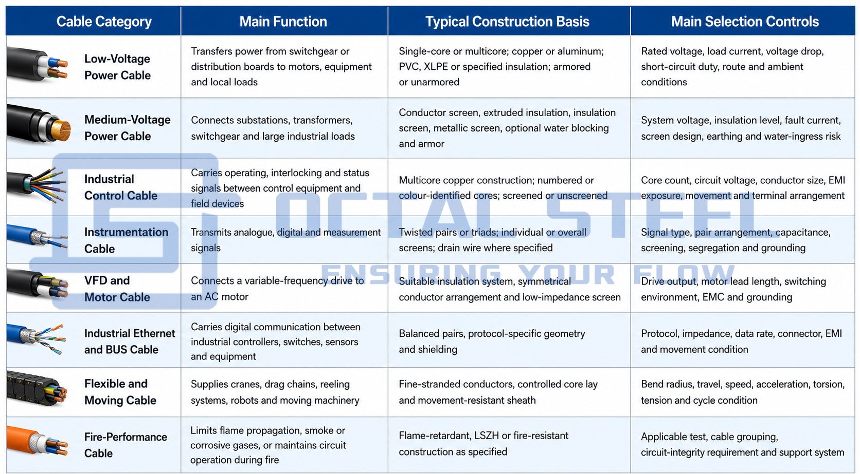
Industrial Cable Types and System Functions
Low-Voltage Industrial Power Cable
Low-voltage power cables distribute energy from transformers, low-voltage switchboards and motor-control centres to motors, pumps, heaters, process packages and local panels. They may use copper or aluminum conductors, single-core or multicore construction, extruded insulation, optional armor and an outer sheath selected for the route environment.
The final conductor size is not determined by load current alone. Voltage drop, short-circuit withstand, grouping, ambient temperature, installation method and terminal compatibility must also be checked.
Medium-Voltage Industrial Power Cable
Medium-voltage cables connect incoming substations, transformers, switchgear, large motors and plant distribution systems. Their construction normally includes a conductor screen, extruded insulation, insulation screen and metallic screen because electrical-field control forms part of cable performance.
The enquiry should state system voltage, insulation level, fault current, screen arrangement, earthing philosophy, water-ingress risk and termination system. These inputs affect the complete cable and accessory design.
Industrial Control Cable
Control cables connect PLC cabinets, relays, contactors, limit switches, valves and machine-control devices. They normally contain multiple identified cores, but conductor count alone does not define a suitable cable.
Screening, conductor flexibility, core identification, voltage rating and the way the cable enters panels or junction boxes also affect the final construction. A fixed multicore control cable should not automatically be used in a drag chain or moving machine axis.
Instrumentation Cable
Instrumentation cables carry low-energy measurement signals between field instruments and control or safety systems. Twisted pairs or triads help maintain circuit balance, while individual or overall screens reduce induced interference where correctly designed and terminated.
The cable schedule should identify the required pair or triad arrangement, individual-pair screen, overall screen, drain wire, grounding philosophy and circuit segregation.
VFD and Motor Cable
A cable between a variable-frequency drive and a motor operates under a switching waveform that differs from a conventional mains-fed motor circuit. The insulation system, conductor arrangement, screen, protective conductors, grounding and termination must therefore be coordinated with the drive and motor.
A general multicore power cable should not automatically be offered as a VFD cable. The quotation basis should identify drive output, motor data, cable length, EMC requirement, grounding method and termination arrangement.
Industrial Ethernet and BUS Cable
Industrial communication cables connect controllers, industrial switches, remote I/O, sensors, drives and machine networks. Their pair geometry, characteristic impedance, shielding and connector compatibility must correspond with the intended protocol.
Fixed cabinet wiring, outdoor plant routing and continuous-flex machine cabling may require different constructions even when the same network protocol is used.
Flexible and Moving Cable
Flexible and moving cables are used in drag chains, cranes, robots, reeling systems, festoons and moving machine axes. A fine-stranded conductor can make installation easier, but it does not automatically make the complete cable suitable for repeated movement.
Continuous-flex performance depends on conductor strand design, core lay, fillers, screen construction, outer sheath and the complete movement profile.
Industrial Cable Construction
An industrial cable is a coordinated system of conductive, insulating, screening and protective layers. Not every cable contains every layer shown below.
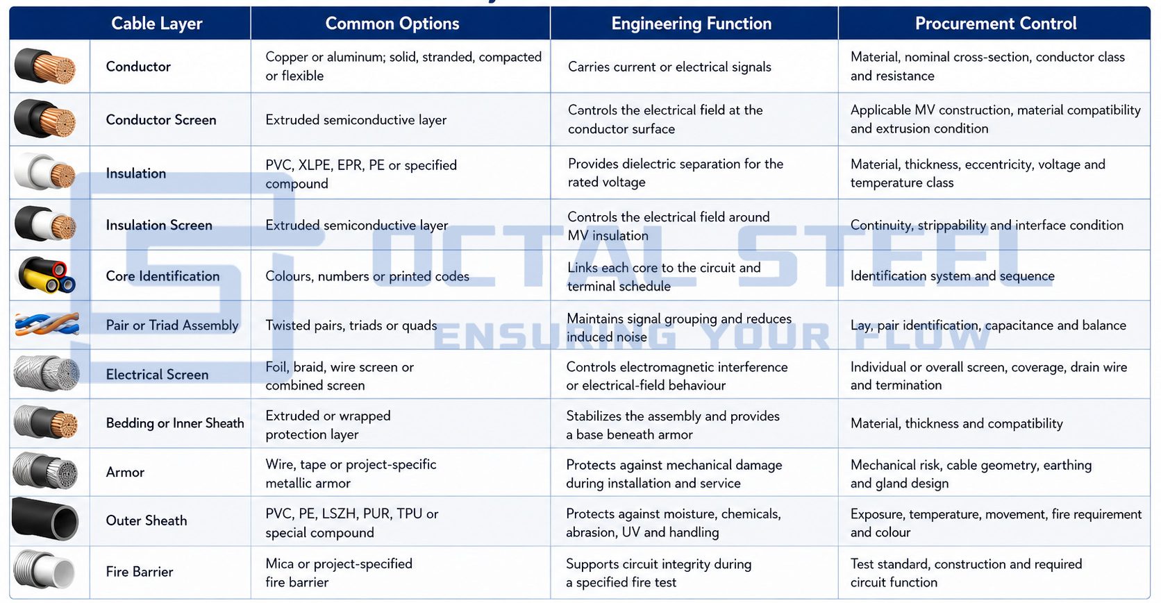
Changing one layer may alter the finished cable diameter, bending behaviour, flexibility, gland selection, termination method and fire classification. Conductor screens and insulation screens are normally associated with applicable medium-voltage designs and should not be shown as universal layers in every cable.
Conductor Sizing and Installation Conditions
Conductor selection begins with continuous load current, but the final cross-section also depends on allowable conductor temperature, voltage drop, short-circuit current and the clearing time of the protective device.
Grouping in cable trays, enclosed ducts, high ambient temperatures, poor soil thermal conditions and harmonic loading can reduce usable current capacity. Pulling force, minimum bending radius, gland size and equipment terminals must also be checked.
A cable schedule should therefore state the electrical duty and installation condition rather than listing only a conductor size and nominal voltage.
Fixed, Flexible and Continuous-Movement Cables
The word flexible can describe several different operating conditions. A flexible installation cable may be moved during installation and then remain stationary. An occasional-flex cable moves during limited equipment operation, while a continuous-flex cable is repeatedly bent throughout normal service.
The enquiry should identify whether the cable is fixed or moving, together with travel distance, bend radius, speed, acceleration, torsion, reeling tension, unsupported length and expected movement cycle.
For drag-chain installations, cable selection alone is not enough. The cable must have adequate free space inside the chain and should not be forced against adjacent cables or hoses. The reference manual recommends a cable clearance of at least 10% of cable diameter and not less than 2 mm, while larger or heavier components should be arranged to maintain balanced loading in the chain.
Representative Drag-Chain Performance Data
| Reference Construction | Rated Voltage | Minimum Bending Radius | Maximum Reference Speed | Maximum Reference Acceleration | Temperature Reference |
|---|---|---|---|---|---|
| PVC-Based Flexible Drag-Chain Control Cable | 300/500 V or 450/750 V |
7.5D | 180 m/min | 7 m/s² | Fixed: −30 to 80°C; Moving: −5 to 80°C |
| Screened Drag-Chain Control Cable | 300/500 V or 450/750 V |
7.5D | 180 m/min | 7 m/s² | Fixed: −30 to 80°C; Moving: −5 to 80°C |
| Single-Core Drag-Chain Power Cable | 600/1000 V | 7.5D | 180 m/min | 7 m/s² | Fixed: −30 to 80°C; Moving: −5 to 80°C |
| Drag-Chain Signal or Data Cable | 350 V | 7.5D | 180 m/min | 7 m/s² | Fixed: −30 to 80°C; Moving: −5 to 80°C |
Note: D represents the finished cable diameter. These values are representative catalogue references and must be confirmed against the selected cable construction and approved project datasheet.
These are construction-specific catalogue references rather than universal limits. Actual service life also depends on travel, chain geometry, installation clearance, torsion, cable weight and the way the cable is secured.
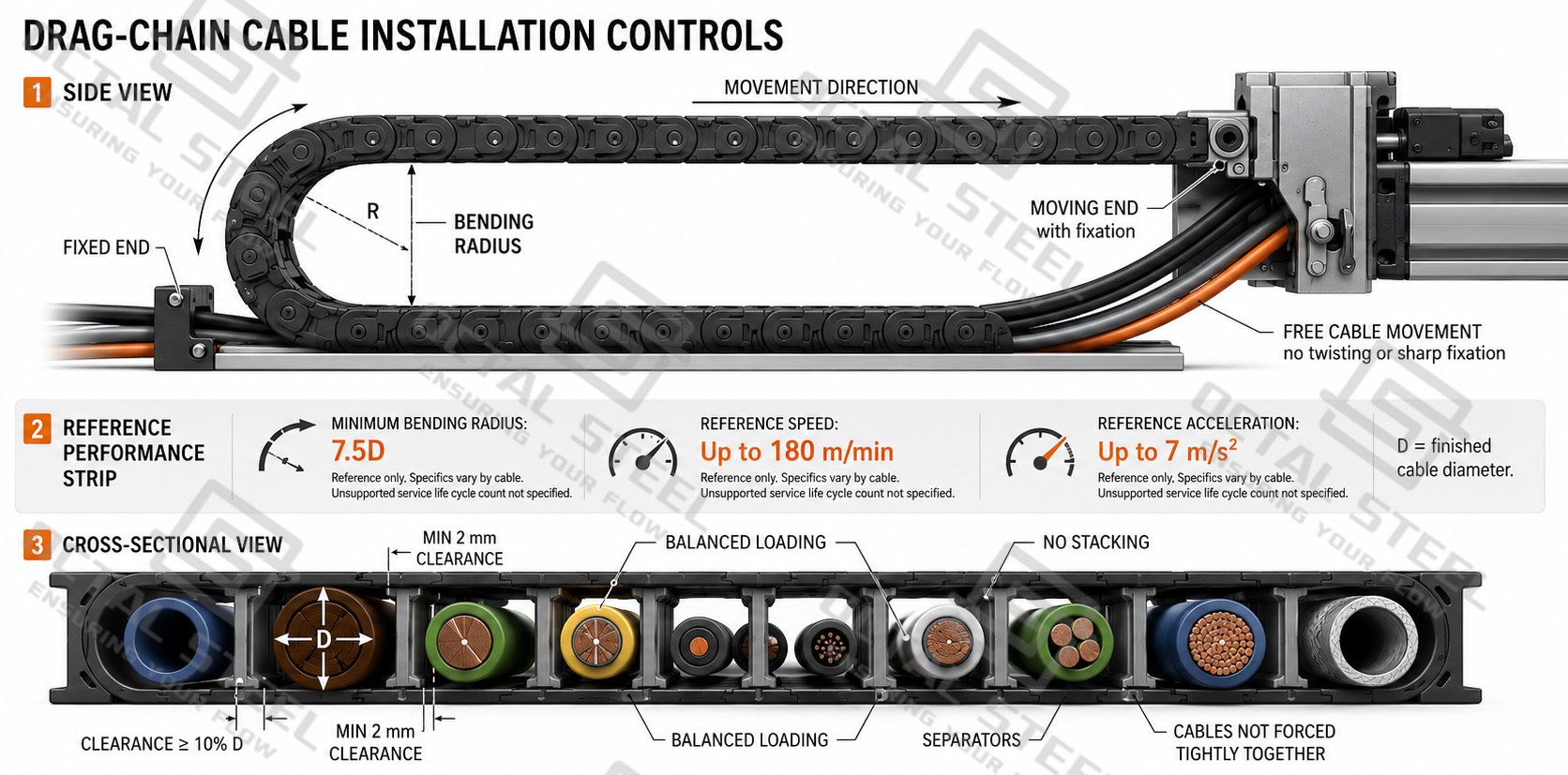
Signal and Data Cable Electrical Controls
Signal and data cables must be selected according to their transmission characteristics, electromagnetic environment and termination system, rather than by conductor size alone. The main controls include:
- Pair or triad arrangement: Twisted conductors keep related signal circuits together, improve electrical balance and reduce externally induced noise.
- Working capacitance and inductance: These values affect circuit loading, signal response and the practical transmission distance between field devices and control equipment.
- Characteristic impedance: Industrial Ethernet and BUS cables must match the impedance required by the specified communication protocol to control signal reflection and data errors.
- Pair balance: Stable conductor spacing and pair geometry help reduce common-mode noise and maintain consistent signal transmission along the cable route.
- Electrical screening: Individual pair screens, overall foil screens, braids or combined screens are selected according to the surrounding electromagnetic interference.
- Transfer impedance: This value indicates the effectiveness of the cable screen under a stated frequency condition and is particularly relevant near motors, drives and power circuits.
- Screen continuity and grounding: The electrical screen must remain continuous through the cable gland or connector and connect correctly to the equipment grounding arrangement.
- Connector compatibility: The connector, cable diameter, pair geometry and shield termination must remain compatible so that the designed transmission performance is not lost at the equipment interface.
Representative Engineering Example: Drag-Chain Data Cable for a Moving Automation Axis:
In a moving automation system, a drag-chain data cable may connect an industrial switch or remote I/O module to sensors, encoders or control devices installed on a travelling machine axis. During normal operation, the cable is repeatedly bent and accelerated inside the cable carrier. Selection therefore depends on the complete cable construction, not only on conductor size or the general description “flexible cable.”
For the referenced construction, the catalogue data includes a rated voltage of 350 V, a test voltage of 1500 V for one minute, insulation resistance above 20 MΩ·km, working capacitance not exceeding 150 nF/km and inductance of approximately 0.65 mH/km. The minimum bending radius is 7.5D, with maximum reference values of 180 m/min travel speed and 7 m/s² acceleration. Here, D represents the finished cable diameter.
The main engineering risk is loss of stable signal transmission after repeated movement. Excessive bending, insufficient cable clearance, unsuitable pair geometry or interrupted screen continuity can increase mechanical stress and contribute to intermittent communication errors. The cable must therefore be checked against:
- the communication protocol and required characteristic impedance;
- pair or triad construction and conductor identification;
- working capacitance and inductance limits;
- individual or overall screening arrangement;
- screen continuity through the gland or connector;
- transfer impedance where specified;
- drag-chain bend radius, travel distance and unsupported length;
- operating speed, acceleration and cycle duty;
- connector geometry, cable diameter and termination method;
- fixed and moving temperature conditions.
These values belong only to the referenced drag-chain data-cable construction. Final selection must be confirmed against the approved cable datasheet, cable schedule, protocol requirement, movement profile, installation route, connector system and project inspection documents.
Cable Sheath and Environmental Protection
The outer sheath must be selected against actual exposure rather than only by material name or colour.
| Sheath or Insulation Material | Typical Engineering Use | Main Controls |
|---|---|---|
| PVC | Fixed and flexible industrial wiring under defined temperature and fire conditions. | Temperature, oil exposure, flame requirement and installation movement. |
| PE | Outdoor, underground or moisture-exposed fixed routes. | Water resistance, UV exposure, burial condition and mechanical protection. |
| PUR or TPU | Moving equipment and installations exposed to abrasion, impact or oil. | Compound type, bend duty, chemical exposure and operating temperature. |
| LSZH Compound | Installations requiring limited smoke and halogen-related emissions. | Applicable flame, smoke, halogen and gas-emission test requirements. |
| Silicone Rubber | High-temperature applications requiring cable flexibility. | Tear resistance, abrasion, operating temperature and mechanical protection. |
| PFA | High-temperature and chemically demanding applications. | Maximum temperature, chemical exposure, conductor plating and termination method. |
| FEP | High-temperature wiring below the applicable PFA temperature range. | Temperature, dielectric requirement and installation method. |
| ETFE | Applications requiring mechanical strength with elevated-temperature performance. | Temperature, abrasion resistance and circuit voltage. |
A general material name does not prove a complete performance level. For example, PUR compounds differ in hydrolysis, oil, abrasion and low-temperature behaviour, while LSZH does not automatically mean that a cable can maintain circuit operation during fire.
Armored and Shielded Industrial Cables
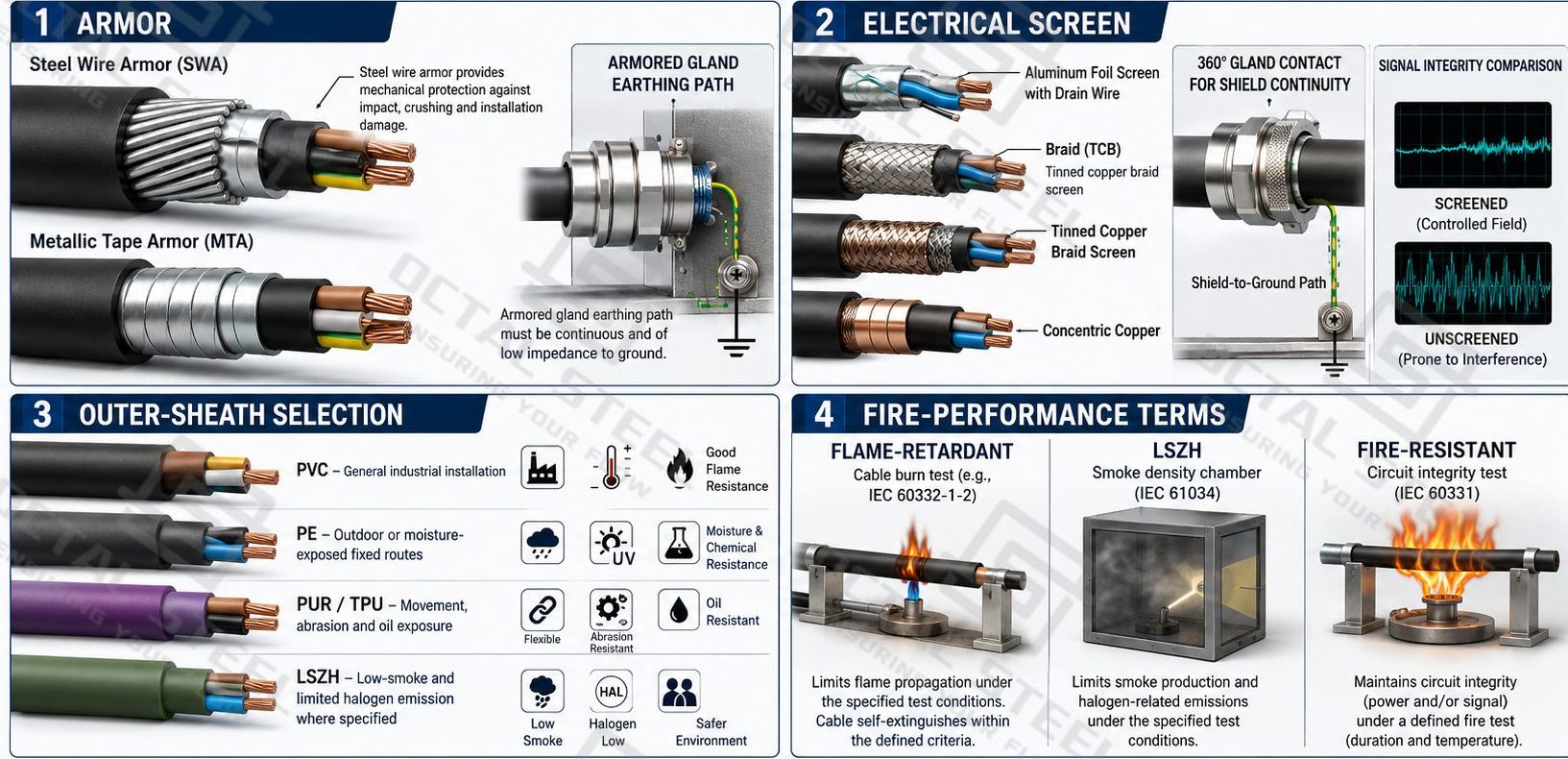
Armor and electrical screening perform different functions.
Armor provides mechanical protection against impact, crushing, pulling and installation damage. It may form part of the bonding or earthing arrangement where permitted, but it must not automatically be treated as a dedicated electromagnetic screen.
An electrical screen reduces electromagnetic interference or controls the electrical field. It may be applied around individual pairs, the complete core assembly or an applicable medium-voltage insulation system.
The enquiry should specify armor and screening separately, including armor material, screen type, coverage, drain wire, grounding, gland and termination method.
Flame-Retardant, LSZH and Fire-Resistant Are Not the Same
A flame-retardant cable is evaluated for limited flame propagation under a specified test method. A test on one vertical cable and a test on a group of bunched cables represent different fire conditions.
An LSZH cable is intended to limit smoke and halogen-related emissions. It may reduce smoke and corrosive gases without maintaining an energized circuit.
A fire-resistant cable is designed to maintain circuit integrity under a defined fire test for a specified time and installation arrangement.
These descriptions should not be combined into a generic claim such as “fireproof cable.” The purchase specification must state the applicable test, required circuit function and cable-support arrangement.
Applicable Industrial Cable Standards
| Standard | Main Relevance |
|---|---|
| IEC 60228 | Conductor nominal cross-section, construction and resistance. |
| IEC 60227 Series | PVC-insulated cables within the applicable lower-voltage classes. |
| IEC 60502-1 | Extruded-insulation power cables at applicable 1 kV and 3 kV classes. |
| IEC 60502-2 | Extruded-insulation power cables in applicable medium-voltage classes. |
| IEC 60811 Series | Dimensional, physical and material test methods for cable compounds. |
| IEC 60332 Series | Flame-propagation testing for single or bunched cables. |
| IEC 60754 Series | Gases and halogen-related emissions from cable materials. |
| IEC 61034 Series | Smoke-density measurement. |
| IEC 60331 Series | Circuit integrity under defined fire conditions. |
The purchase order should state the required standard edition, regional approval and project specification. An IEC-based cable should not automatically be described as UL Listed, CSA certified or compliant with another national approval unless supporting documentation is available.
Download:Industrial_Cable_Selection_Construction_and_Installation.pdf
Manufacturing and Quality Control
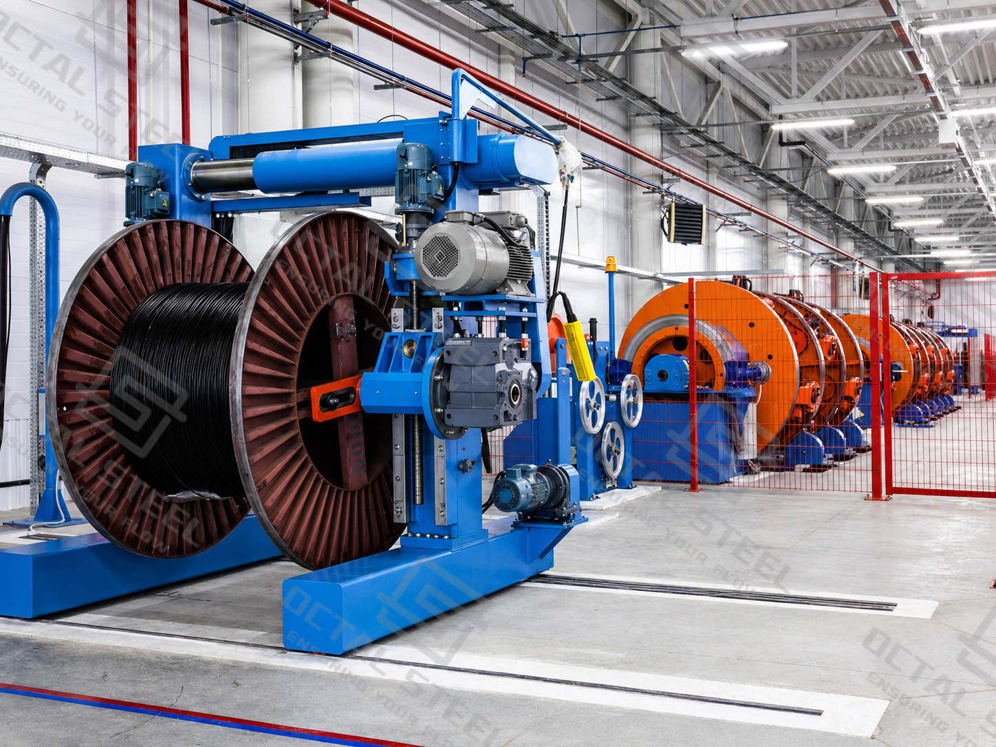
Industrial cable production begins with the approved datasheet and cable schedule. Conductor material, cross-section, insulation, core arrangement, screening, armor, sheath compound, marking and drum length are confirmed as one complete construction before manufacturing.
Conductor Formation
Copper or aluminum wires are drawn and assembled into the specified solid, stranded, compacted or flexible conductor. Wire condition, strand arrangement, conductor diameter and electrical resistance are checked because they influence electrical performance, flexibility and terminal compatibility.
Insulation and Core Assembly
PVC, XLPE, EPR, PE or another specified compound is extruded around the conductor. Insulation thickness, concentricity and surface condition are verified before cores are identified and assembled in the required sequence. Instrumentation pairs or triads must remain linked to the signal schedule.
Screening, Armor and Outer Sheath
Foil, braid, wire screen, metallic screen, bedding and armor are applied where required. Continuity, overlap, coverage, arrangement and finished diameter are checked against the approved construction. The outer sheath is then extruded in the specified material and inspected for thickness, surface condition, marking and overall dimensions.
Electrical and Construction Testing
Testing follows the applicable product standard and approved inspection plan. Typical release checks include conductor resistance, conductor and screen continuity, insulation and sheath dimensions, finished cable diameter, voltage withstand, insulation resistance where applicable, core identification, construction verification, marking and measured length.
Medium-voltage, data, fire-performance and continuous-movement cables may require additional routine, sample, type or special tests. One universal test list or inspection percentage should not be applied to every cable family.
Drum Winding and Final Release
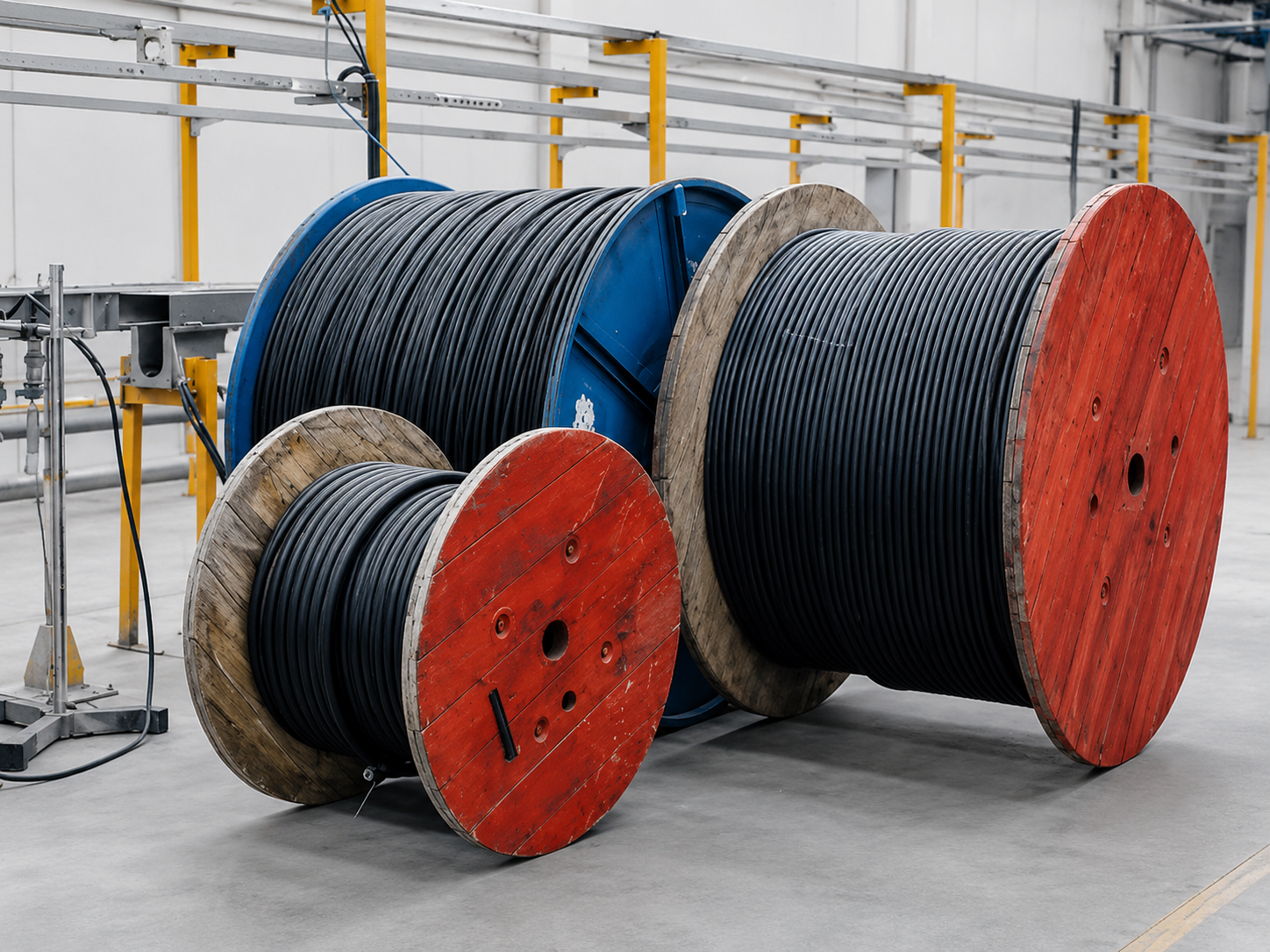
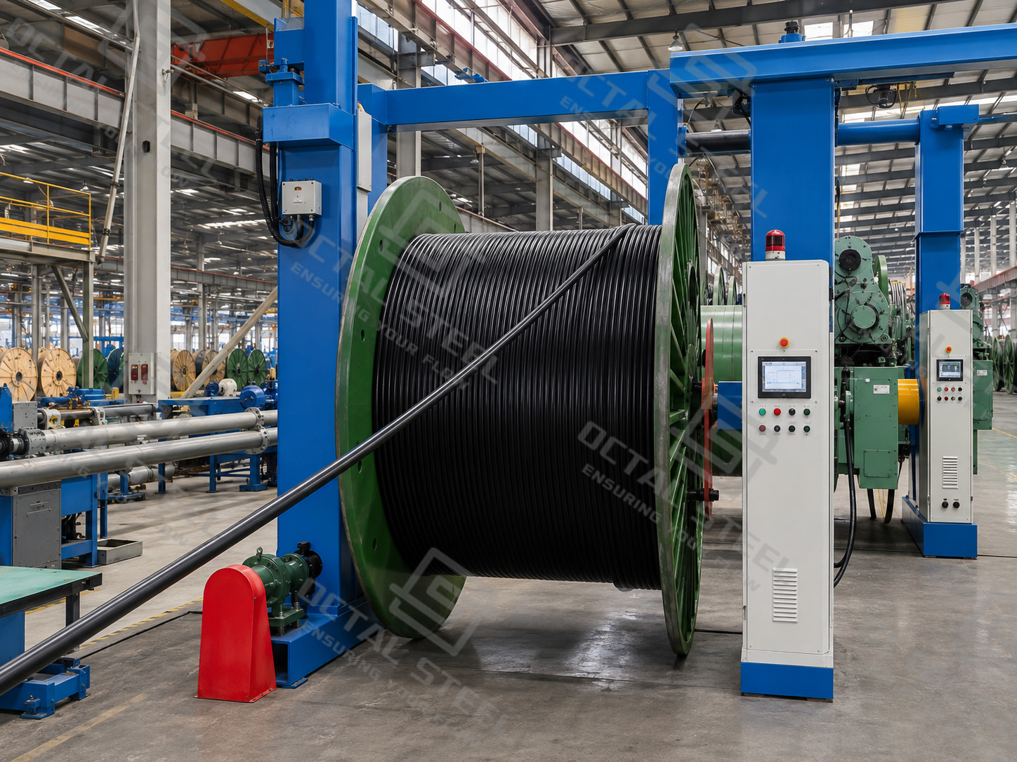
The finished cable is wound onto a drum selected for its diameter, weight, bending requirement and transport condition. Cable ends are sealed against moisture, while the drum number, measured length, cable marking, test-report reference and packing-list entry are checked before release.
Download:Industrial_Cable_Manufacturing_Inspection_and_Drum_Release.pdf
Industrial Cable Applications
Industrial Cable Supply from Octal
Octal treats the cable construction, cable schedule, drum allocation and release documents as one coordinated supply package. Quotations are developed from the circuit function and installation condition rather than from a general request for “heavy-duty cable.”
The supply scope can include power, control, instrumentation, VFD, industrial data and flexible cables with project-defined conductor, insulation, screen, armor, sheath and fire-performance options. Cable lengths, marking, drum allocation, glands, lugs, connectors, inspection records and export packing can also be coordinated where included in the order.
A preliminary quotation may be developed from an available cable list or plant layout. Final manufacture requires an approved cable datasheet and cable schedule so that construction, lengths, markings, accessories and documents correspond with the installation package.
FAQ
Q: What information is required to select an industrial cable?
A: Provide the circuit function, voltage, current, conductor size, route length, installation method, environmental exposure, movement duty, screening, armor, fire requirements and applicable standard.
Q: What is the difference between power, control and instrumentation cable?
A: Power cable carries operating current, control cable carries switching and interlocking signals, and instrumentation cable carries low-energy measurement signals through defined pairs, triads and screens.
Q: When should an industrial cable be armored or screened?
A: Armor is selected mainly for mechanical protection. Screening is selected for electromagnetic interference or electrical-field control. Some installations require both.
Q: Can a flexible industrial cable be used in a drag chain?
A: Not automatically. A drag-chain cable must be selected for the required bend radius, travel, speed, acceleration, torsion and movement cycle. A stranded conductor alone does not establish continuous-flex suitability.
Social Share