Your Responsible Supplier Partner for Oil and Gas Products.

Coal Silo
Recent Products




Rencent Articles

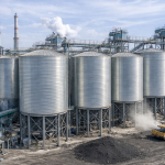




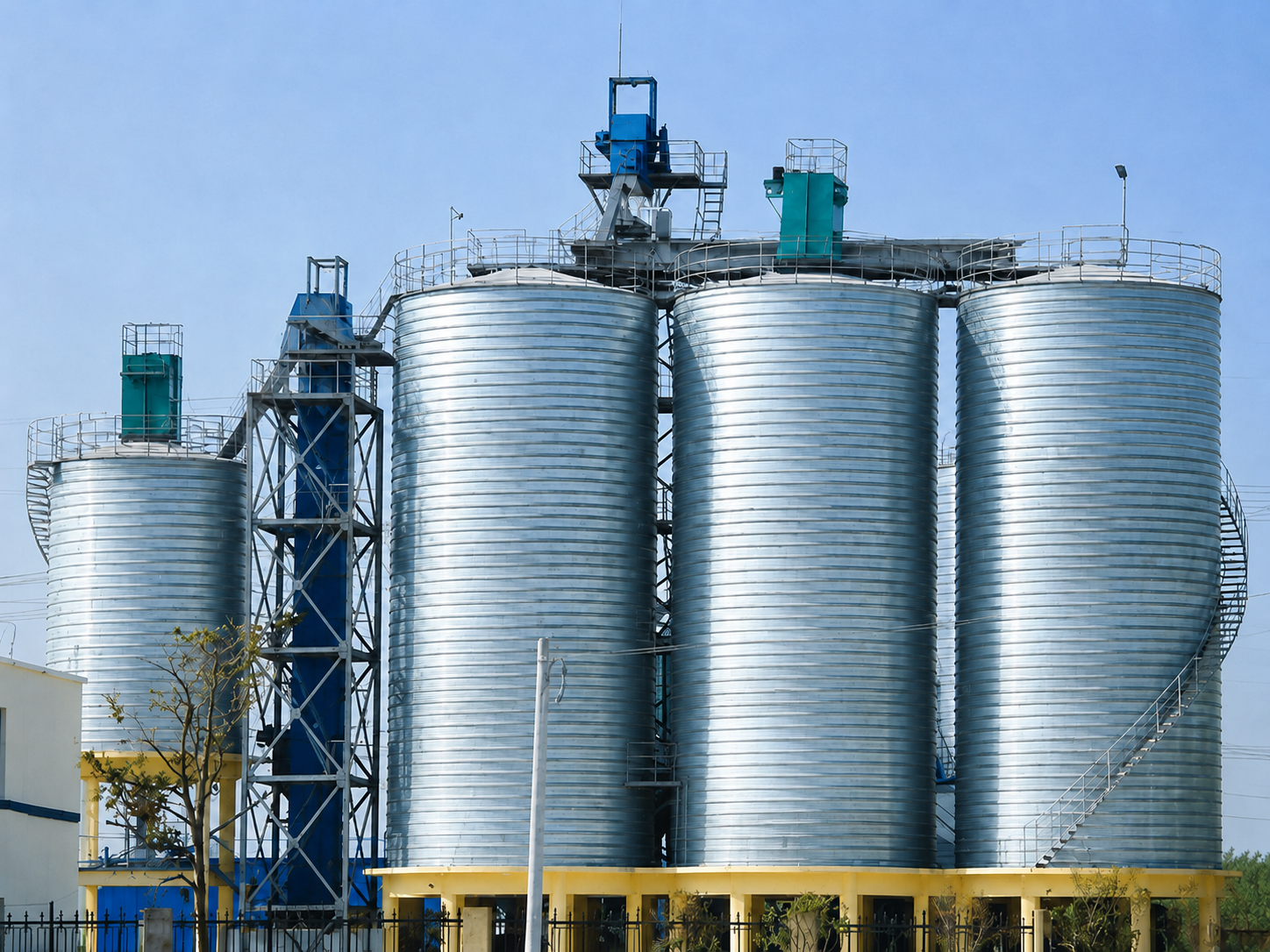
Coal Silo
Silo Types: Spiral-formed, bolted and welded steel silos with hopper-bottom or flat-bottom configurations.
Storage Function: Enclosed storage protects coal from weather while controlling dust, moisture exposure and material loss.
System Integration: Compatible with belt conveyors, inlet distributors, vent filters, level sensors, temperature monitoring and controlled-rate feeders.
Applications: Coal-fired power plants, coal mines, coking plants, industrial boiler systems, ports and bulk-material terminals.
A coal storage silo is an enclosed bulk-storage structure used to receive, store and discharge raw coal, crushed coal, washed coal or selected coal fines. It provides a controlled material buffer between incoming conveyors and downstream crushers, mills, boilers, blending systems or loading equipment. Compared with open stockpiles, a steel coal silo requires less plant area, protects the stored material from direct rain and helps contain dust around the handling system. It is commonly installed in coal mines, preparation plants, thermal power stations, coking plants, industrial boiler facilities, ports and railway terminals.
Octal Steel supplies project-engineered coal silos with spiral-formed galvanized steel shells, together with roofs, hoppers, structural reinforcement, outlets, supporting steelwork, access platforms and interfaces for feeding, conveying, dust collection and condition monitoring. Each silo is configured according to the required working capacity, coal bulk density, moisture, particle-size distribution, filling rate, discharge rate and installation environment. These operating inputs determine the usable volume, silo dimensions, hopper geometry, outlet arrangement and feeder capacity.
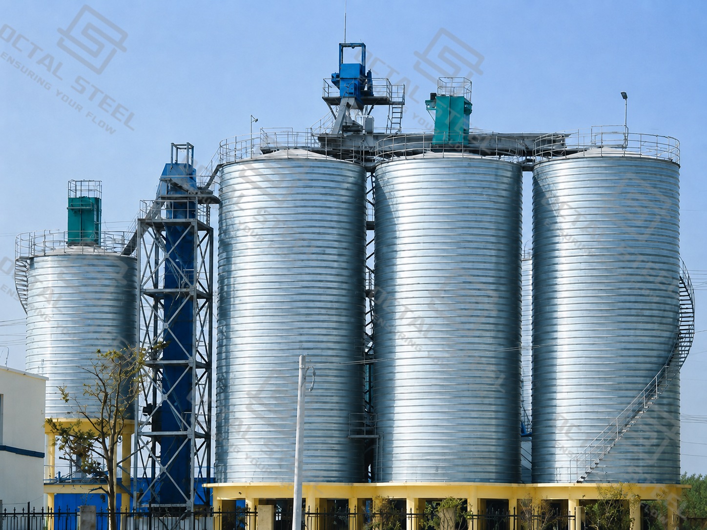
Coal Silo Specifications
The following ranges describe the available configurations. Final dimensions and structural details are established during project engineering.
| Parameter | Available Range or Configuration |
|---|---|
| Silo diameter | 3–28 m |
| Silo height | Up to 28 m |
| Storage capacity | Calculated for each project |
| Shell material | Galvanized steel |
| Shell construction | On-site spiral forming with double-folded seams |
| Bottom arrangement | Inverted-cone hopper |
| Discharge arrangement | Single, double or multiple outlets |
| Insulation and cladding | Available according to climate and operating conditions |
These values do not represent one standard coal silo design. Shell thickness, structural reinforcement, hopper configuration and foundation loads must be calculated for the selected capacity, coal properties, connected equipment and local environmental loads.
The working storage capacity is calculated from the usable internal volume and the actual bulk density of the coal under operating conditions:
Working storage capacity = usable internal volume × actual coal bulk density
Usable volume is lower than the gross geometric volume. Roof clearance, the maximum filling level, hopper space, residual material and operating reserve must all be considered. Bulk density should represent the coal in its expected moisture and compaction condition rather than a generic dry value.
Coal Silo Capacity Calculation Examples
The same usable silo volume can represent different coal tonnages because bulk density varies with coal type, particle-size distribution, moisture and handling conditions. The following examples show how the selected design bulk density affects estimated working storage capacity.
| Usable Internal Volume | At 0.75 t/m³ | At 0.85 t/m³ | At 0.95 t/m³ |
|---|---|---|---|
| 1,000 m³ | 750 t | 850 t | 950 t |
| 3,000 m³ | 2,250 t | 2,550 t | 2,850 t |
| 5,000 m³ | 3,750 t | 4,250 t | 4,750 t |
These figures are calculation examples rather than guaranteed storage capacities. Actual working capacity must be based on the measured coal bulk density and usable internal volume after deducting roof clearance, filling limits, hopper space, residual material and the required operating reserve.
Download:coal silo technical specifications and capacity calculation
Spiral-Formed Steel Silo Structure
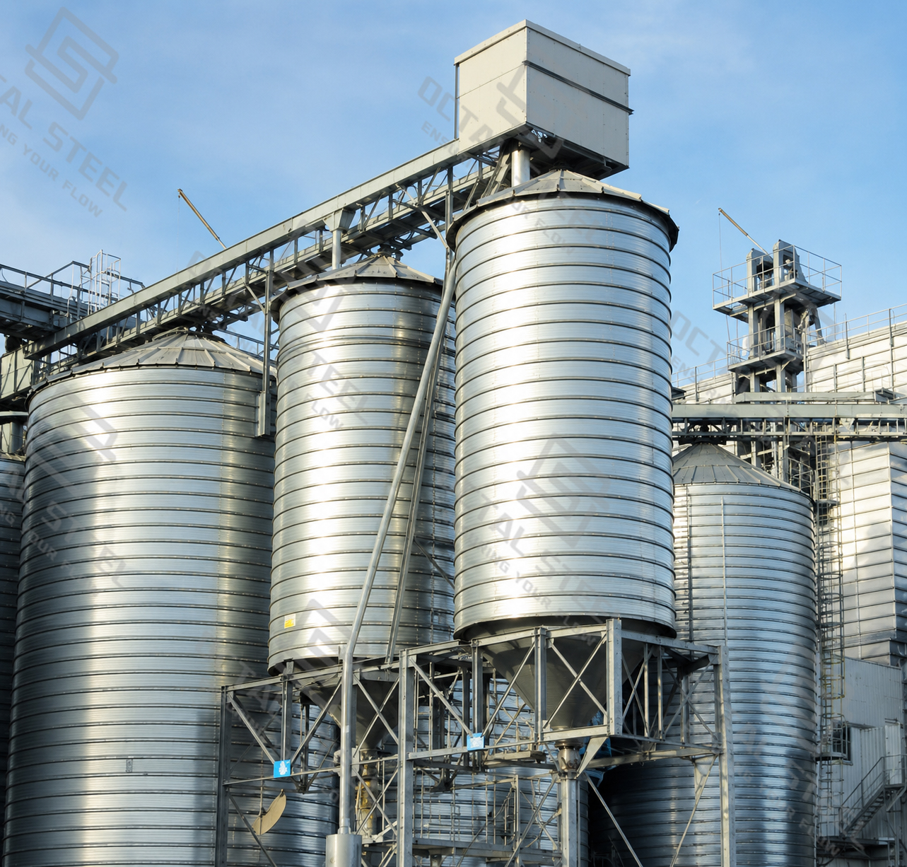
The cylindrical shell is constructed on site using continuously formed galvanized steel strip. The strip is curved to the required diameter, and adjacent edges are mechanically folded together to create a double-seam spiral connection.
This construction method produces a continuous cylindrical wall without conventional rows of bolted lap joints through the main shell. Forming the shell at the installation site also reduces the need to transport large prefabricated wall sections and allows the dimensions to be coordinated with the available plant layout.
Vertical stiffeners, roof framing and reinforcement around openings are added according to the structural calculation. Particular attention is given to roof inlets, manholes, instrument penetrations, outlet transitions and connections to the foundation.
The spiral-forming process describes how the shell is constructed; it does not define the complete silo performance. A reliable coal silo design must also account for material flow, structural loads, discharge equipment, dust control and coal-storage hazards.
Lipp Silo for Coal Storage
Lipp silo is a spiral-formed steel storage system manufactured on site from continuous steel strip. During construction, the strip is curved to the required silo diameter and its adjacent edges are mechanically joined through a continuous double-fold seam. The cylindrical shell rises progressively as the forming equipment travels around the silo circumference.
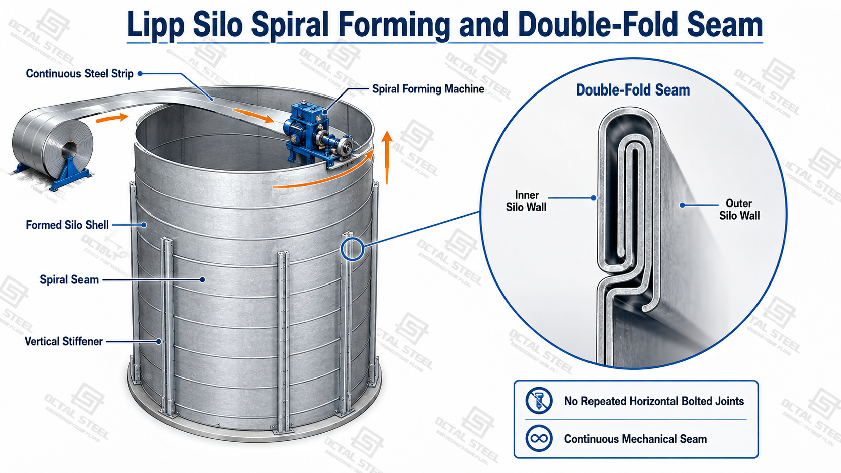
For coal storage, this construction method provides a continuous steel shell without the repeated horizontal bolted joints used in conventional sectional silos. On-site forming also reduces the need to transport large prefabricated shell sections and allows the silo diameter and height to be adapted to the required storage capacity and available site layout.
A complete Lipp coal silo can incorporate the roof structure, hopper or flat-bottom discharge system, vertical reinforcement, access platforms, level instruments, temperature-monitoring cables, ventilation connections and dust-collection interfaces. The filling and reclaim arrangement must be coordinated with the required throughput and coal-flow characteristics.
The Lipp construction process determines how the shell is formed and connected, but the silo must still be engineered for the actual project conditions. Stored-coal density, moisture, particle-size distribution, filling and discharge loads, wind, snow, seismic actions, corrosion exposure and combustible-coal-dust hazards must all be considered during design.
How the Coal Storage Silo Works
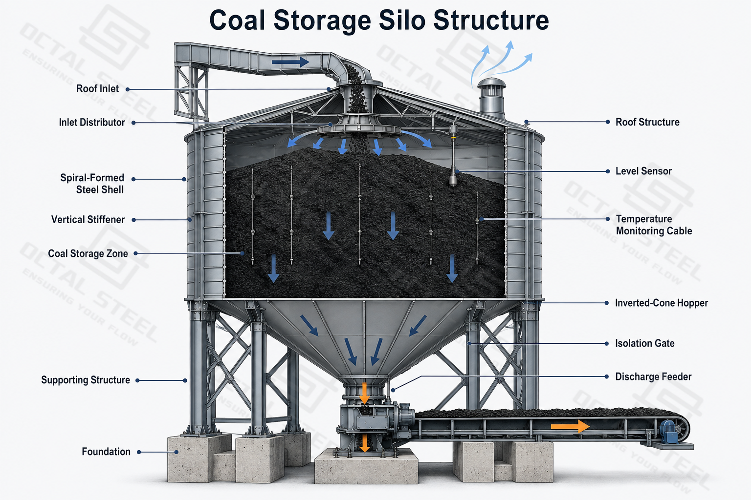
Coal normally enters through a roof inlet connected to a belt conveyor, bucket elevator or enclosed transfer chute. Where a long free-fall distance could cause segregation or concentrated impact, an inlet distributor or impact-protection arrangement can be incorporated.
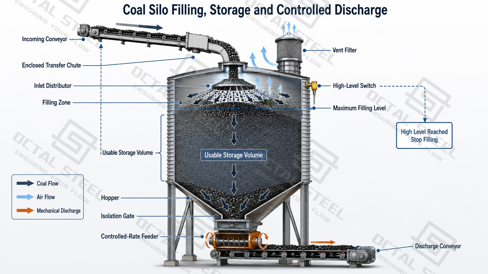
Air displaced during filling carries suspended coal dust toward the roof. A vent filter or connection to the central dust-collection system controls this airflow and limits dust release around the filling point.
Continuous level measurement allows operators to monitor the inventory of coal stored in the silo. An independent high-level switch can stop the incoming conveyor if the permitted filling level is reached.
Coal is discharged through an inverted-cone hopper and one or more outlets. Isolation gates provide shutoff for maintenance, while feeders regulate the flow to the downstream conveyor, crusher, mill, boiler or loading system.
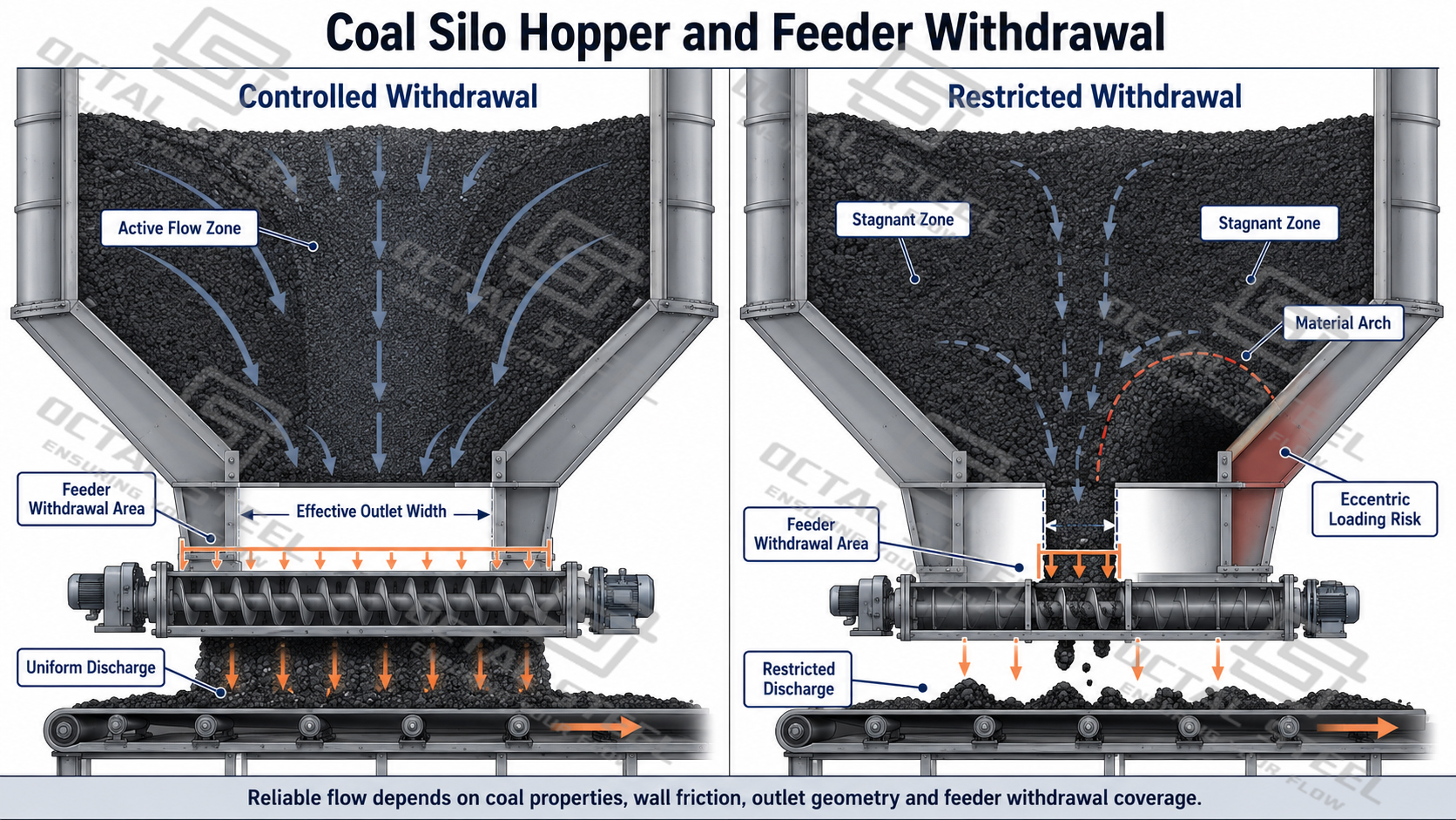
The hopper, outlet and feeder must operate as one system. A large outlet alone does not ensure reliable flow if the feeder withdraws material from only a limited area. Where multiple outlets are installed, their operating sequence should also avoid prolonged off-centre discharge and uneven structural loading.
Coal Silo Design and Selection
A suitable silo cannot be selected from nominal tonnage alone. Four groups of information have the greatest effect on its practical performance.
Required Working Capacity
Capacity should be based on the actual operating cycle of the plant. The calculation normally considers:
- Normal and maximum filling rates;
- Required discharge rate;
- Buffer time during upstream interruptions;
- Minimum operating stock;
- Planned inventory rotation;
- Allowance for unusable or residual material.
For example, a silo supplying a boiler during a conveyor shutdown requires a different capacity basis from a surge silo used to balance truck- or train-loading cycles.
Increasing gross volume without considering retention time is not always beneficial. Excessively long storage can increase coal consolidation, wall adhesion and self-heating risk.
Coal Properties
The material information used for selection should include maximum lump size, particle-size distribution, moisture range, fines content, loose and compacted bulk density, storage duration and incoming temperature.
Wet coal with a high percentage of fines may adhere to the hopper wall or form a stable bridge above the outlet. Frozen lumps, timber or metal objects can obstruct the opening and damage the feeder. The design should therefore be based on the most difficult expected operating material rather than only a clean, dry sample.
Representative flow testing should be considered when the coal is wet, cohesive, compressible or highly variable. Test results can help determine the appropriate hopper inclination, wall surface and minimum outlet dimensions.
Discharge Requirements
The required reclaim rate influences the number and size of outlets, gate arrangement and feeder capacity. The feeder must handle the expected maximum lump size and moisture condition while remaining compatible with the downstream conveyor or processing equipment.
Double or multiple outlets may be used for higher reclaim rates or more even withdrawal. Their positions and operating sequence should be included in the structural and process design.
Vibrators, air cannons or other flow-assistance devices can be included when justified by the material behaviour. They should support a correctly designed discharge system rather than compensate for an undersized outlet.
Site and Environmental Conditions
Silo diameter and height must be coordinated with the available footprint, conveyor elevations, maintenance access and foundation conditions. A taller silo can reduce the required ground area but may increase wind effects and foundation loads.
The structural calculation should consider applicable wind, seismic, snow, roof-equipment and conveyor loads. Coastal, humid or chemically aggressive environments may require additional corrosion protection.
Insulation and external cladding can be supplied where condensation, coal freezing or large temperature variations could affect storage and discharge.
Representative Coal Silo Design Standards
The design basis for a coal storage silo depends on the project location, silo configuration, stored-coal properties and contractual requirements. The following standards cover three principal areas: stored-material actions, steel-silo structural design and combustible-dust safety.
| Standard | Technical Scope | Application to Coal Silo Design |
|---|---|---|
| EN 1991-4 | Actions on silos and tanks | Stored-material pressures and actions generated during filling and discharge |
| EN 1993-4-1 | Structural design of steel silos | Structural resistance and stability of the shell, roof, hopper and stiffening system |
| NFPA 660 | Combustible dusts and particulate solids | Coal-dust hazard assessment, ignition control and protection strategy |
The applicable standards and editions must be confirmed in the project specification. Where the hazard assessment requires explosion venting, prevention or isolation, standards such as NFPA 68 and NFPA 69 may also apply. Wind, snow, seismic actions, foundation design and environmental exposure must follow the codes adopted for the project location.
Coal Flow and Storage Safety
Safe operation of a coal storage silo depends on reliable material flow, controlled storage time and appropriate monitoring. The required measures vary with coal rank, particle size, moisture, incoming temperature and plant operating conditions.
Arching and Outlet Blockage
Arching occurs when cohesive coal forms a stable bridge above the outlet. It is more likely with wet fines, clay contamination, long storage periods or an opening that is too small for the material.
The primary controls are suitable hopper geometry, adequate outlet dimensions and a feeder that activates the intended withdrawal area. Upstream screening, crushing or tramp-metal removal may also be required where oversized or foreign material is possible.
Repeated blockage should not automatically be treated by installing stronger vibration equipment. The coal condition, hopper geometry, outlet and feeder arrangement should first be reviewed.
Coal Self-Heating
Coal can oxidize during storage and release heat. The risk is influenced by coal rank, moisture, fines content, oxygen availability, incoming temperature, retention time and stagnant zones.
Controls may include planned inventory rotation, limited storage time and monitoring of temperature and carbon monoxide trends. Temperature cables and CO sampling points can be incorporated where required by the operating and fire-safety strategy.
A rising trend is generally more useful than one isolated reading. Alarm limits and operator responses should therefore be established for the individual project.
Ventilation is not a universal response to self-heating because additional oxygen can intensify oxidation. O₂ monitoring, inert-gas connections or other protective systems should be selected through a project-specific fire assessment.
Coal-Dust Control
Dry coal fines can produce suspended combustible dust during filling, discharge and conveying. Dust control should therefore cover the complete connected handling route, including transfer chutes, silo vents, feeders, conveyors and dust collectors.
Typical measures include enclosed transfer points, dust extraction, grounding and ignition-source control. Hazardous-area electrical equipment, explosion isolation, engineered venting or suppression may also be required, depending on the project risk assessment.
The routine vent used to release displaced air during filling should not automatically be treated as explosion protection. Normal pressure relief and dust-explosion relief perform different functions.
Coal Silo Applications
Thermal Power and Industrial Boiler Plants
Coal silos provide buffer storage between stockyard handling, crushing and fuel-preparation systems. Controlled discharge supports a consistent supply to mills or boiler feeders when the upstream conveying rate fluctuates.
Coarse-coal storage and pulverized-coal storage are different duties. Their flow characteristics and fire-protection requirements should be assessed separately.
Coal Mine Silo Applications
A coal mine silo can receive run-of-mine, screened, crushed or washed coal before processing, transportation or loading. Its inlet protection, hopper geometry, outlet dimensions and feeder type are selected according to the maximum lump size, moisture range and fines content.
Compared with silos serving controlled boiler-plant feed, coal mine silos may experience greater variation in incoming material size and moisture. The selected design must accommodate these changes without relying on one idealized coal sample.
Coking and Coal-Blending Plants
Multiple silos can keep different coal grades separated before controlled proportioning and blending. Consistent feeder output helps maintain the required blend delivered to the crushing and coke-oven charging systems.
Ports and Railway Terminals
At bulk terminals, coal silos provide surge storage between incoming conveyors and ship, train or truck-loading systems. These installations may require high reclaim rates, multiple outlets and coordinated dust control across the connected conveying route.
Coastal projects also require suitable allowances for wind loading, salt exposure, rain penetration and external corrosion.
Why Choose Octal Steel
Octal Steel supplies more than the cylindrical shell. Each project is reviewed as an integrated storage, filling and discharge system.
The available project scope can include:
- Review of coal properties and required working capacity;
- Configuration of silo diameter, height and usable volume;
- Structural design of the shell, roof, stiffeners and hopper;
- Coordination of inlet, outlet, feeder and conveyor interfaces;
- Interfaces for dust collection and level measurement;
- Provisions for temperature and gas monitoring;
- Corrosion protection, insulation and external cladding;
- Platforms, ladders, guardrails and maintenance access;
- Foundation loads and civil-interface information;
- Material certificates, inspection records and installation documents.
Before design is finalized, the coal bulk density, moisture range, particle-size distribution, filling rate, reclaim rate and expected storage duration are reviewed. These inputs provide the basis for the usable volume, hopper geometry, outlet arrangement and feeder capacity.
Inspection can cover steel-material certification, thickness, galvanized coating condition, seam geometry, silo diameter, roundness, vertical alignment, reinforcement and roof sealing.
During commissioning, the filling pattern, dust collection, level signals, high-level shutdown, outlet flow, feeder performance and alarm interlocks can be checked under controlled operating conditions.
FAQ
Q1: How is coal silo capacity calculated?
A1: Coal silo capacity is calculated by multiplying the usable internal volume by the actual bulk density of the coal under operating conditions. Roof clearance, filling limits, hopper space, residual coal and operating reserve must be deducted from the gross volume. Filling rate, discharge rate and required buffer time should also be considered.
Q2: What information is required for a coal silo design?
A2: The main inputs include required working capacity, coal bulk density, moisture, particle-size distribution, maximum lump size, filling rate, discharge rate and expected storage duration. Site wind, seismic, snow, temperature, corrosion exposure and foundation conditions are also required for structural design.
Q3: How can blockage in a coal storage silo be reduced?
A3: Reliable discharge depends on suitable hopper geometry, adequate outlet dimensions and a feeder that withdraws coal across the intended opening. Moisture, fines content, cohesion, maximum lump size and storage duration must be evaluated. Flow-assistance equipment may be added where justified, but it should not compensate for an undersized outlet.
Q4: How are self-heating and coal-dust hazards controlled?
A4: Controls may include inventory rotation, limited retention time, temperature and CO monitoring, dust collection, grounding, ignition-source control and alarm interlocks. O₂ monitoring, inert-gas connections or engineered explosion protection may also be required. The final system must be based on the coal properties, operating conditions and project-specific hazard assessment.