Your Responsible Supplier Partner for Oil and Gas Products.

E75 Drill Pipe
Recent Products
Rencent Articles

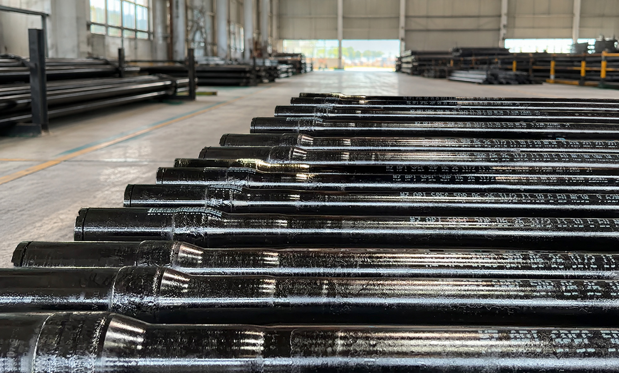
E75 Drill Pipe
Supply Range of Diameters: 2-3/8” to 6-5/8”
Range of Length: R1, R2 or R3
Upset Type: IU, EU, IEU
Connection Options: NC26 to NC50, 5-1/2 FH, 6-5/8 FH
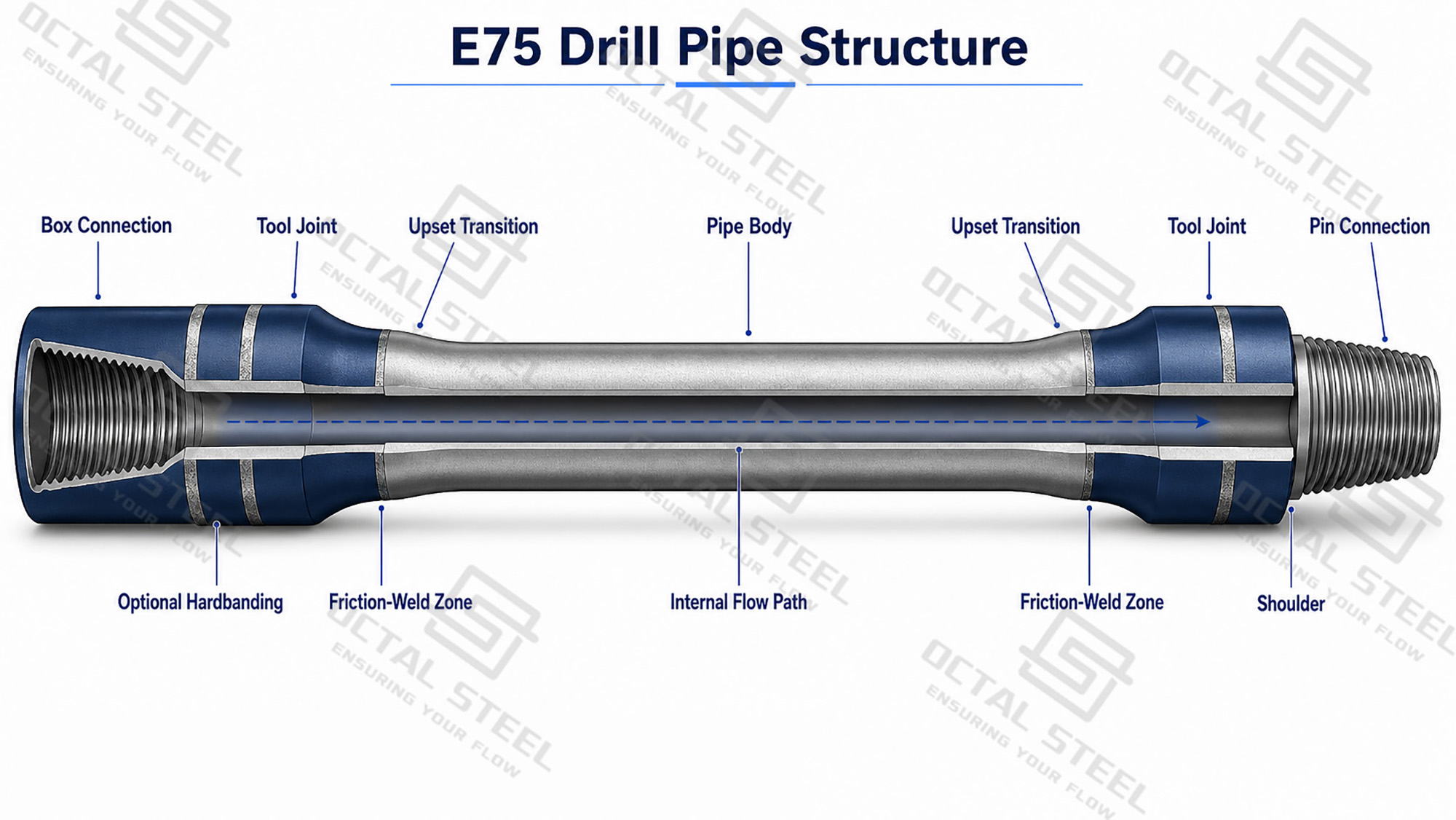
Tool Joint: Friction-welded pin and box
Optional Features: Hardbanding, internal coating, thread protectors
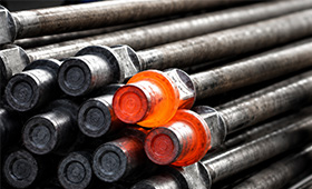
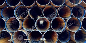
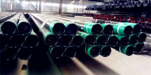
E75 drill pipe in various sizes and configurations.
Suitable for rotary drilling strings requiring Grade E pipe-body strength.
E75 drill pipe is used in rotary drilling strings to transmit torque, carry axial load and circulate drilling fluid through the internal bore. It is built from a seamless, heat-treated pipe body with upset ends and friction-welded pin and box tool joints. Under API 5DP, the Grade E pipe body has a specified yield-strength range of 75–105 ksi (517–724 MPa) and a minimum tensile strength of 100 ksi (689 MPa). These values identify the pipe-body grade, but the capacity of the finished joint must still be checked against pipe size, wall thickness, tool-joint geometry, connection and remaining wall condition.
E75 Drill Pipe Standards
| Standard | Application to E75 Drill Pipe |
|---|---|
| API Spec 5DP, 2nd Edition, including Addendum 1 and current errata | Manufacturing, dimensions, material requirements, testing, marking and technical delivery of finished drill pipe |
| ISO 11961:2018 with Amendment 1:2020 | International technical delivery conditions for steel drill pipe with upset pipe-body ends and weld-on tool joints |
| API Spec 7-2 / ISO 10424-2 | Threading and gauging of rotary shouldered tool-joint connections |
| API RP 7G | Drill-stem design calculations, performance properties and operating limits |
| ISO 15156 / NACE MR0175, when specified | Material review for drilling equipment exposed to H2S-containing fluids |
These standards define the manufacturing, connection, inspection and technical-delivery basis for E75 drill pipe. The final purchase specification should still confirm the pipe-body size, nominal weight, upset type, tool-joint dimensions, connection, PSL and project-specific inspection requirements. For a more detailed summary of API 5DP grades, dimensions, mechanical properties and acceptance data, download the technical reference below.
Download :API Spec 5DP Drill Pipe Data Reference
E75 Drill Pipe Specifications
| Specification Item | Available Range or Requirement |
|---|---|
| Product Standard | API Spec 5DP; ISO 11961 |
| Pipe-Body Grade | E75 |
| Construction | Seamless heat-treated pipe body with upset ends and friction-welded pin and box tool joints |
| Pipe-Body OD | 2-3/8 to 6-5/8 in. / 60.3 to 168.3 mm |
| Nominal Weight | Selected according to pipe OD and API 5DP body configuration |
| Wall Thickness | Selected according to nominal weight and required pipe-body capacity |
| Upset Type | IU, EU or IEU |
| Tool Joint | Weld-on pin and box; OD and minimum ID confirmed by approved data sheet |
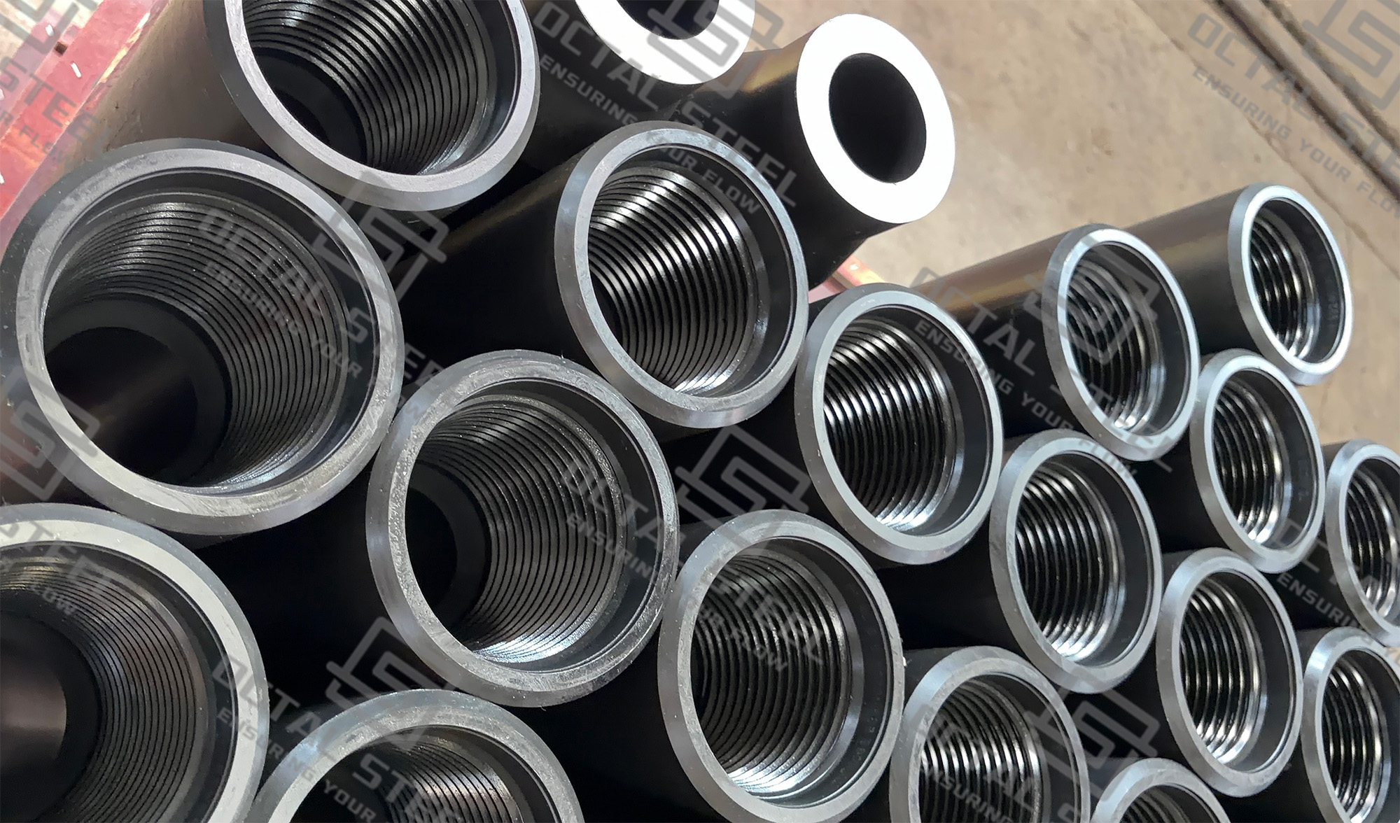
| Connection Options | NC26, NC31, NC38, NC40, NC46, NC50, 5-1/2 FH, 6-5/8 FH or project-specified connection |
| Length Range | R1: 18–22 ft; R2: 27–31 ft; R3: 38–45 ft |
| Product Specification Level | PSL-1, PSL-2 or PSL-3, as specified in the purchase order |
| Optional Features | Tool-joint hardbanding, internal coating and thread protectors |
| Inspection Documents | MTC, mechanical-test report, weld-zone NDT, dimensional report, thread-gauging record and packing-list traceability |
The ranges above describe the available configuration variables rather than fixed combinations. Pipe OD, nominal weight, upset type, tool-joint OD/ID and connection are interdependent, so the final dimensions must follow the approved product data sheet. The connection options shown are therefore references and are not automatically assigned to every pipe size.
Download :E75 Drill Pipe Specification and Selection Guide
E75 Drill Pipe Mechanical Properties
| Property | API 5DP Grade E75 Requirement | Verification |
|---|---|---|
| Minimum yield strength | 75 ksi / 517 MPa | Tensile report linked to pipe-body heat and heat-treatment lot |
| Maximum yield strength | 105 ksi / 724 MPa | Result must remain inside the Grade E strength window |
| Minimum tensile strength | 100 ksi / 689 MPa | Verified from the identified tensile specimen |
| Minimum elongation | Calculated from specimen area under API 5DP | Reported with specimen dimensions |
| Grade E phosphorus | 0.030% maximum | Heat analysis on MTC |
| Grade E sulfur | 0.020% maximum | Heat analysis on MTC |
These E75 drill pipe mechanical properties apply to the pipe body. The tool joint, friction-weld zone, connection and complete drill string are evaluated separately because each section has its own dimensions, material condition and load capacity.
The specified E75 drill pipe yield strength is a material acceptance range, not a direct hook-load or overpull rating. Available tensile capacity changes with pipe-body cross-sectional area, wall loss, combined torque and the design factor used for the drilling program. In some configurations, the connection or tool joint becomes the controlling section before the pipe body reaches its yield limit.For drilling programs that require a different strength margin, see our API 5DP drill pipe grade selection guide for a comparison of E75, X95, G105 and S135.
Grade E is defined by mechanical performance and specified chemistry limits rather than one fixed alloy recipe. Carbon, manganese, chromium and molybdenum may vary with the approved steelmaking route, while the actual heat analysis and tensile results are reported on the MTC. API 5DP limits phosphorus to 0.030% maximum and sulfur to 0.020% maximum for Grade E; the applicable weld-zone hardness limit for Grades E, X, G and S is 37 HRC.
E75 Drill Pipe Length and End Configuration
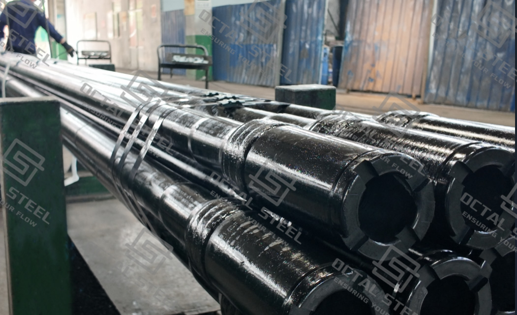
Finished E75 drill pipe may be supplied in the following length ranges:
| Length Range | Finished Joint Length |
|---|---|
| R1 | 18–22 ft |
| R2 | 27–30 ft |
| R3 | 38–45 ft |
R2 is commonly requested for standard land-drilling strings, while R1 may suit compact workover equipment and R3 may reduce the number of connections in selected drilling programs. Final joint length and tolerance must be stated in the purchase specification.
The upset and tool joint should be treated as part of the pipe design:
• IU—Internal Upset: thickening is directed mainly inward and reduces the end bore.
• EU—External Upset: thickening is directed mainly outward and preserves more internal clearance.
• IEU—Internal-External Upset: material is added on both sides to create the required weld section and transition.
A larger tool-joint OD can improve connection section but reduce annular clearance. A smaller tool-joint ID may increase hydraulic pressure loss or restrict drift passage. Neither dimension should be changed independently without reviewing connection capacity and the drill-pipe torsion-strength ratio.
E75 Drill Pipe Manufacturing and Inspection
E75 drill pipe is produced through a controlled sequence:
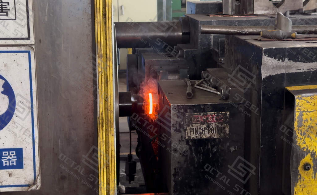
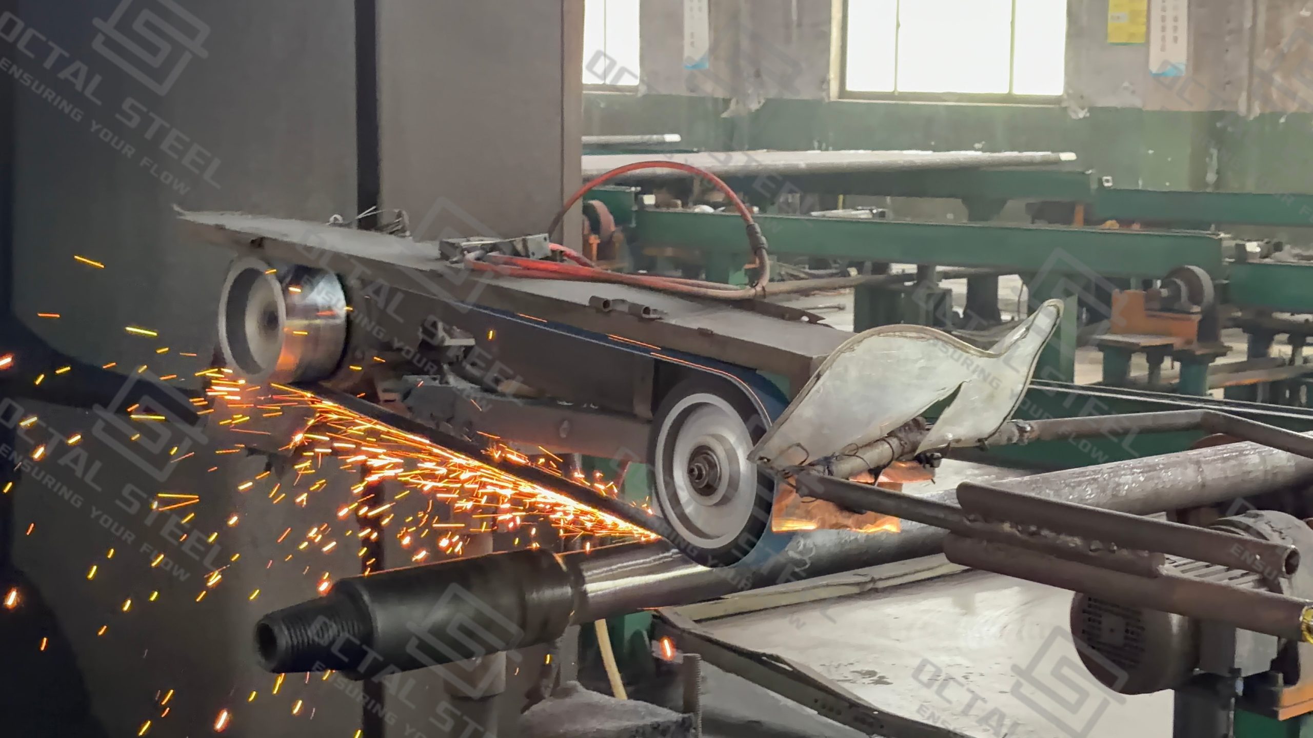
Seamless pipe body → end upsetting → full-length heat treatment → mechanical testing → tool-joint production → friction welding → weld treatment and flash removal → NDT → connection machining and gauging → final release
The important point is not the number of production stages, but whether the records remain connected from raw material to finished joint.
| Control Point | What Is Checked | Release Evidence |
|---|---|---|
| Pipe Body | OD, wall thickness, straightness and Grade E mechanical results | MTC and tensile report |
| Upset Transition | Internal profile, external shape, alignment and surface condition | Upset dimensional report |
| Tool Joint | Material identity, OD, ID, hardness and connection | Tool-joint inspection record |
| Friction Weld | Alignment, flash removal, weld profile, hardness and NDT acceptance | Weld-lot report |
| Pin and Box | Thread form, shoulder condition and gauge result | API 7-2 gauging report |
| Final Joint | Length, drift, marking, protectors and bundle identity | Final inspection and packing list |
The current API 5DP addendum requires wall-thickness verification along the pipe body and a documented method for areas not covered by automated inspection, particularly near the upset transition. For Grade E weld zones, no surface hardness result may exceed 37 HRC.
The finished traceability chain should remain continuous:
Pipe marking → pipe-body heat → heat-treatment lot → mechanical test → tool-joint heat → weld lot → weld-zone NDT → thread gauging → packing list
E75 Drill Pipe Applications
Surface-Hole Drilling with a Short String
During conductor and surface-hole drilling, the suspended drill string is still relatively short and accumulated drag is limited. E75 can be considered where calculated hook load, mud weight, rotary torque and required overpull remain inside the capacity of the selected pipe-body size and connection.
The review should still account for large-hole vibration, intermittent impact and tool-joint wear. A short string does not remove the need to verify connection torque or hydraulic clearance.
Vertical Intermediate Hole Before Kickoff
In a near-vertical intermediate section, pick-up load, slack-off load and rotating torque are generally easier to control than in a long build-and-hold interval. E75 may be suitable where the drilling model retains adequate tensile and overpull margin.
Once the string begins passing repeatedly through a pronounced dogleg, fatigue at the upset transition, friction weld and connection becomes more important. Grade selection should then include rotation count and dogleg severity, not only measured depth.
Drilling Out a Casing Shoe or Cement Plug
E75 drill pipe can be used to drill out float equipment, a shoe track or a cement plug under controlled weight on bit and rotary torque. Before starting, the connection and overpull margin should be checked against the risk of bit stall, packed cuttings and temporary sticking.
Repeated high-torque stalls, aggressive back-reaming or extended milling can move the operation outside the original E75 load basis even though the well remains nearly vertical.
Workover, Wash-Down and Cleanout
A smaller E75 string may be used for circulation, wash-down, scale removal and controlled cleanout where the fluid program, tensile load and rotary demand are known.
Heavy fishing, repeated jarring, high-overpull recovery or aggressive milling should not automatically use the same string. Those operations require a separate combined-load review and may justify a different grade, wall section or connection.
Short Sidetracks and Low-Dogleg Sections
E75 may also be used in a short sidetrack or low-angle tangent where torque and drag remain moderate. The critical check is the number of rotations through the curved interval. A pipe body can remain below its static yield limit while the upset or connection accumulates fatigue damage from repeated bending.
These examples show why E75 should not be described simply as a “shallow-well grade.” Its suitability depends on the actual load path, well profile and drill-string configuration.
Why Choose Octal Drill Pipes
Octal does not treat E75 drill pipe as a grade-only product. Each order is reviewed as a complete assembly, including pipe-body OD, nominal weight, wall thickness, upset type, tool-joint OD and ID, connection, length range, hardbanding, internal coating and inspection level. This helps prevent common specification problems such as restricted bore clearance, incompatible connections or tool-joint dimensions that do not match the intended drilling string.
During production and final release, the pipe-body heat, tool-joint heat, friction-weld lot, mechanical-test results, weld-zone inspection and thread-gauging records remain linked to the finished joints. Markings, thread protectors, bundle identification and packing-list information are checked against the purchase order before shipment. Where required, third-party inspection, additional NDT or project-specific documentation can be incorporated into the agreed inspection plan.
FAQ
1. Can E75 drill pipe be mixed with X95 or G105 in the same drill string?
Yes, provided the connections, tool-joint dimensions, internal clearance and make-up requirements are compatible. The operating limit of the mixed string must be based on its weakest pipe-body or connection section.
2. How should PSL-1, PSL-2 or PSL-3 be selected?
PSL-1 is the baseline delivery level under ISO 11961. PSL-2 and PSL-3 add further technical requirements and should be specified when the drilling program, client QA plan or inspection authority requires enhanced verification.
3. Is the same connection automatically used for every E75 drill pipe size?
No. Pipe OD does not automatically determine the connection. The selected connection must be checked together with tool-joint OD, minimum ID, upset geometry, torque requirement and mating drill-string equipment.
4. Should hardbanding and internal coating be specified for E75 drill pipe?
They are optional and should match the operating environment. Hardbanding is considered where tool-joint wear requires control, while internal coating may be selected to protect the bore and reduce internal surface deterioration. The material, location and acceptance criteria should be stated in the purchase specification.
5. How should used E75 drill pipe be evaluated before reuse?
Used drill pipe should be inspected for remaining wall thickness, cracks, connection damage, tool-joint wear, straightness and classification status. Acceptance should follow an agreed used-drill-stem inspection procedure, such as API RP 7G-2, rather than relying only on operating history or visual appearance.