Your Responsible Supplier Partner for Oil and Gas Products.

Lime Silo
Recent Products





Rencent Articles

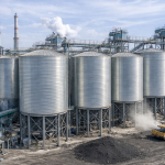





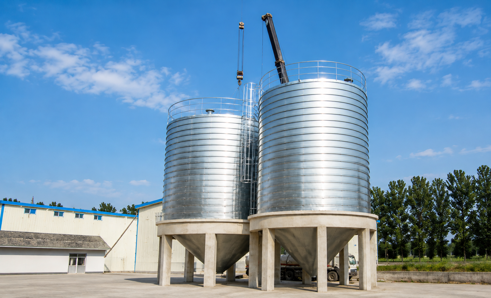
Lime Silo
Stored Materials: Hydrated lime, pulverized quicklime, ground quicklime and suitable pebble lime.
Working Principle: Sealed filling, filtered venting, enclosed storage and controlled metered discharge.
System Configuration: Spiral-formed, welded, bolted or insulated steel silo with hopper, flow aids, level monitoring and pressure protection.
Applications: Water treatment, lime slaking, flue-gas treatment, mineral processing, asphalt production and dry-mix batching.
Lime silo receives dry lime through a sealed pneumatic or mechanical filling line, separates the conveying air through a roof-mounted dust filter, and stores the material inside a moisture-controlled steel enclosure. During discharge, a hopper, flow-promoting device and metering feeder work in sequence to maintain stable material movement and controlled process feeding. This configuration is used for hydrated lime, pulverized quicklime, ground quicklime and suitable pebble lime in water treatment, flue-gas treatment, mineral processing, asphalt production, dry-mix batching and lime-slaking systems.
OCTAL STEEL supplies lime steel silo structures in spiral-formed, welded, bolted and insulated configurations. Each lime storage silo can be coordinated with filling pipework, dust filtration, pressure protection, level monitoring, flow aids and downstream feeding interfaces according to the material form and process duty.
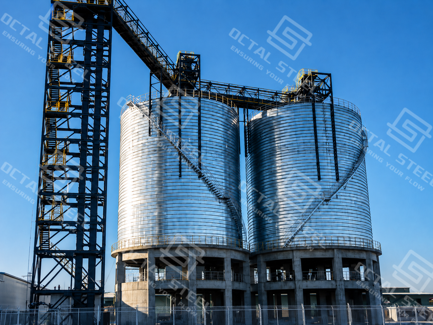
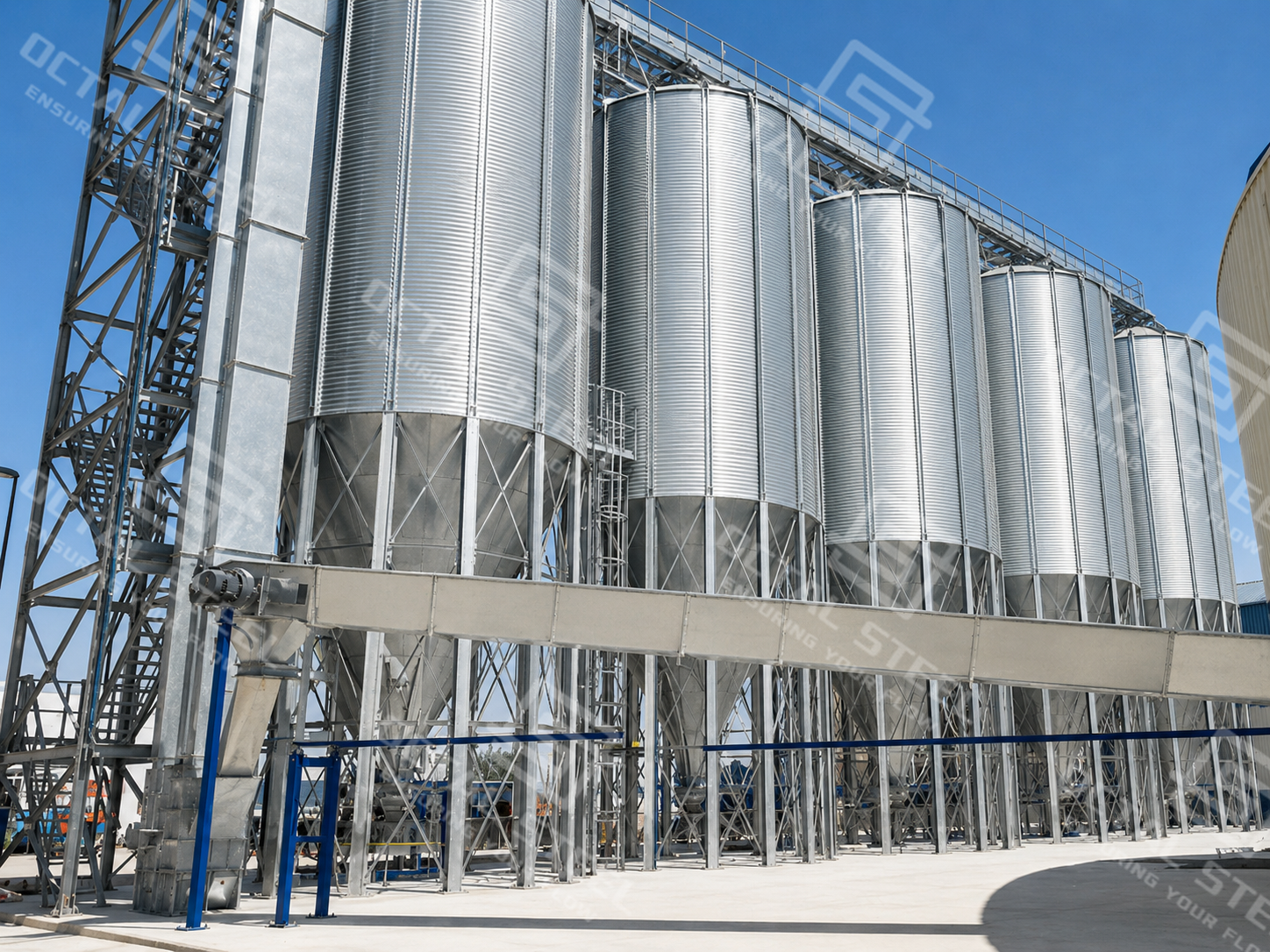
Lime Silo Configurations
A lime silo is configured around the form of the stored material and the duty of the downstream process. A hydrated lime silo used for accurate chemical dosing has different discharge requirements from a quicklime silo feeding a slaking system or a large lime storage silo used for bulk inventory.
| Configuration | Stored Material | Operating Function | Filling Method | Discharge Arrangement |
|---|---|---|---|---|
| Hydrated Lime Process Silo | Fine hydrated lime powder | Continuous or batch dosing | Pneumatic tanker unloading | Bin activator with screw, rotary or gravimetric feeder |
| Quicklime Powder Silo | Ground or pulverized quicklime | Controlled feeding to a slaker | Pneumatic or enclosed mechanical transfer | Metering feeder connected to the slaking system |
| Pebble Lime Silo | Crushed or pebble quicklime | Storage before slaking or industrial processing | Enclosed mechanical conveying or confirmed pneumatic transfer | Gravity outlet with a particle-compatible feeder |
| Lime Day Silo | Hydrated lime or quicklime powder | Short-term process buffering | Upstream conveyor or pneumatic line | Volumetric or loss-in-weight feeder |
| Large Inventory Silo | Confirmed dry lime material | Reserve storage or terminal handling | Pneumatic or mechanical filling | Flat-bottom reclaim, multiple outlets or large hopper system |
| Insulated Lime Silo | Moisture-sensitive lime in exposed environments | Storage under significant temperature variation | Pneumatic or mechanical filling | Protected bottom and process interfaces |
The selected construction must support the required storage mass while maintaining a sealed environment around the roof, shell, access openings, filling connection and discharge transition. Flow performance depends on the lower silo geometry and feeder interface rather than on storage volume alone.
Structure and Working Principle
A lime silo operates as a coordinated receiving, storage, ventilation and feeding system. The cylindrical shell contains the material load, the roof equipment controls air and dust during filling, and the bottom section transfers lime into a feeder at a stable process rate.
Main Structural Components
| Component | Primary Function | Lime-Service Design Consideration |
|---|---|---|
| Silo Roof | Supports filling, filtration and monitoring equipment | Roof penetrations and access covers require dust-tight and weather-resistant sealing |
| Steel Shell | Contains the lime and transfers material and environmental loads | Shell thickness and stiffening depend on stored mass, wall pressure, wind, seismic and equipment loads |
| Filling Pipeline | Transfers lime into the silo | Routing must control wear, impact, blockage and pressure loss |
| Dust Filter | Separates entrained lime from conveying and displaced air | Filtration area and cleaning method must match the maximum filling airflow |
| Pressure/Vacuum Relief Device | Protects the silo against abnormal internal pressure or vacuum | Provides independent mechanical protection when normal ventilation is restricted |
| Pressure Switch | Monitors pressure during filling | Initiates an alarm or filling shutdown before structural protection is activated |
| Continuous Level Instrument | Measures normal inventory | Instrument selection must account for dust and material buildup |
| High-Level Switch | Prevents overfilling | Operates independently from continuous level measurement |
| Hopper or Flat Bottom | Directs stored lime toward the reclaim system | Geometry depends on flow properties, storage scale and required discharge rate |
| Flow-Promoting Equipment | Mobilizes lime in the lower storage zone | May include a bin activator, aeration pads or controlled air injection |
| Isolation Valve | Separates the silo from downstream equipment | Supports maintenance and controlled process startup |
| Metering Feeder | Establishes the process feed rate | Selected according to particle size, accuracy, capacity and downstream duty |
| Support Structure | Transfers silo and equipment loads to the foundation | Layout must maintain access and avoid interference with weighing equipment |
| Access System | Provides access to filters, instruments, manholes and valves | Platforms and ladders must permit inspection and component removal |
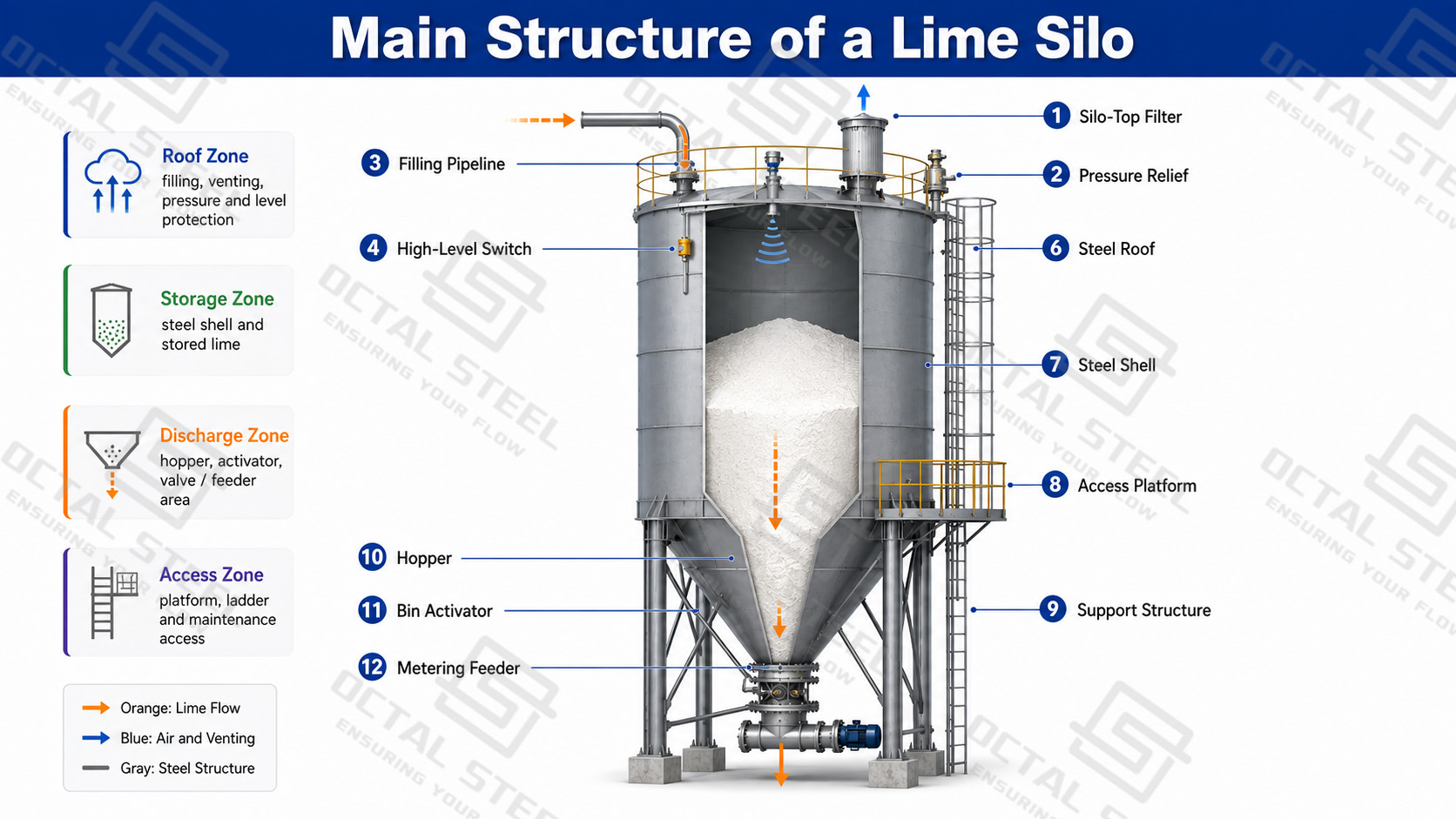
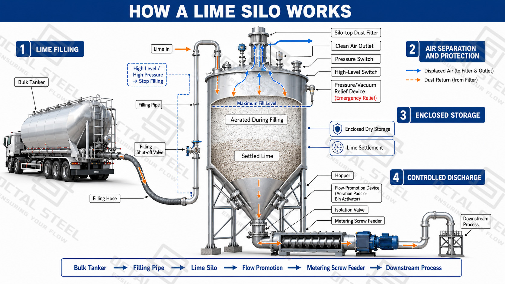
How a Lime Silo Works
Lime silo receives, stores and discharges dry lime through sealed filling, air separation, enclosed storage and controlled feeding. Its function is to keep the lime dry and stable during storage and deliver it at a controlled rate to the downstream process.
Typical process flow:
Bulk Tanker or Conveyor → Filling Pipeline → Dust Filter and Air Venting → Lime Silo Storage Zone → Hopper → Flow-Promoting Device → Isolation Valve → Metering Feeder → Downstream Process
1. Lime Filling
Dry lime enters the silo through a sealed pneumatic filling pipeline or an enclosed mechanical conveyor. During pneumatic filling, lime particles and conveying air enter together. The particles lose velocity inside the silo and fall into the storage zone.
2. Air Separation and Pressure Protection
The conveying air moves upward to the silo-top dust filter. The filter retains lime dust and releases the cleaned air, preventing dust from escaping around the filling point.
A pressure switch monitors the silo during filling, while an independent high-level switch stops material transfer before overfilling occurs. The pressure/vacuum relief device provides structural protection if the normal ventilation path becomes blocked or excessive vacuum develops.
3. Enclosed Storage
After filling, the lime settles and entrained air gradually escapes. The silo shell keeps the material enclosed and limits exposure to rainwater, condensation and humid air.
This is important because hydrated lime can cake and adhere to the wall when moisture enters, while quicklime can react with water and form hardened deposits. The roof joints, manholes, instrument connections and discharge outlet therefore form one continuous moisture-control boundary.
4. Controlled Discharge
When the downstream process requires lime, the metering feeder starts first. The bin activator, aeration pads or other flow-promoting equipment then mobilize the lime in the lower hopper and direct it toward the outlet.
The flow aid maintains material movement, but the feeder determines the final feed rate. This prevents uncontrolled gravity discharge and provides a stable lime supply to the slaker, mixing tank, weigh hopper or dry-injection system.
Download:Lime Storage and Discharge Configuration
Material Behavior and Storage Design
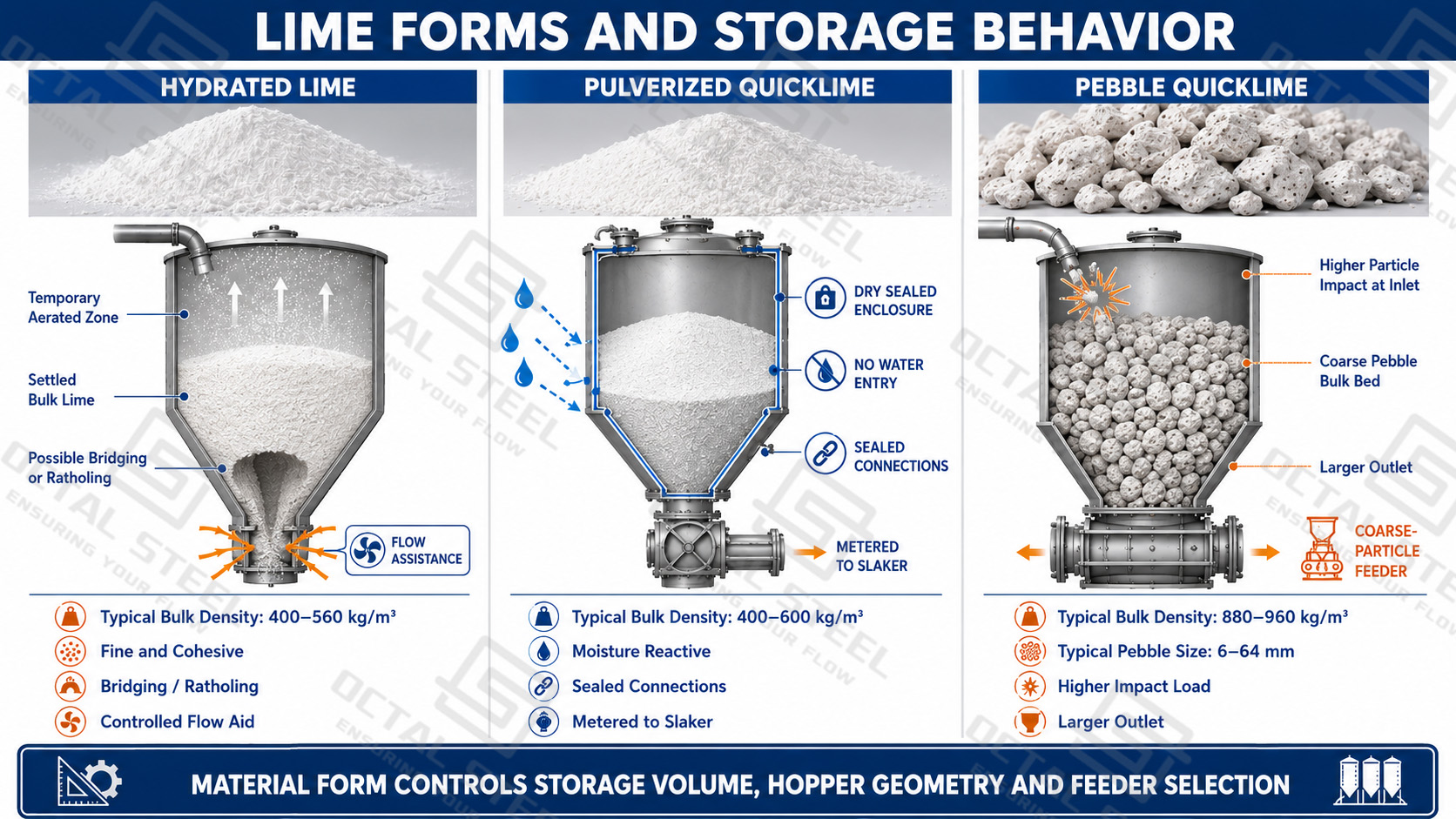
The physical form of lime directly affects silo volume, stored load, filling behavior and discharge stability. Hydrated lime is normally handled as a fine powder that can retain conveying air and consolidate during storage. Pulverized quicklime may show similar powder-flow behavior but requires stricter moisture isolation, while pebble quicklime has a much higher bulk density and produces greater impact at the filling inlet and discharge outlet.
Lime Particle Size and Bulk Density
| Lime Form | Typical Particle Form | Typical Bulk Density | Typical Angle of Repose | Main Effect on Silo Design |
|---|---|---|---|---|
| High-Calcium or Normal Dolomitic Hydrated Lime | Fine powder; normal grades generally have at least 85% passing a No. 200 sieve, approximately 75 μm | 400–560 kg/m³ | Approximately 70°, but actual hydrated lime may vary from 15° to 80° | Low-density powder occupies more volume and can bridge, compact or flood after pneumatic filling |
| Pressure-Hydrated Dolomitic Lime | Fine powder with a relatively higher settled density | 480–640 kg/m³ | Approximately 70° | Higher stored mass requires corresponding shell, hopper and support loading |
| Pulverized Quicklime | Finely ground material, typically substantially passing a No. 20 sieve, approximately 850 μm | Material-specific | Quicklime generally ranges from 50° to 55° | Fine particles require controlled feeding, while all connections must remain isolated from moisture |
| Pebble Quicklime | Approximately 6–64 mm particle range | 880–960 kg/m³ | Approximately 50–55° | Higher bulk mass, particle impact and possible size segregation affect the inlet, outlet and feeder |
Download:Lime Material Behavior and Storage Design
The angle of repose describes how the loose material forms a pile; it is not the same as the required hopper-wall angle. Hydrated lime can show a particularly wide variation because its flow behavior changes with particle fineness, moisture content and degree of aeration.
Bulk Density Changes During Storage
Lime does not retain one constant bulk density throughout filling and storage. Pneumatically conveyed hydrated lime initially contains entrained air and occupies a relatively large volume. As the air escapes, the powder settles and the mass contained in each cubic metre increases.
Different density conditions serve different design purposes:
| Density Condition | Design Use | Effect on the Lime Silo |
|---|---|---|
| Loose Bulk Density | Receiving-volume and free-space calculation | Determines whether the silo can accept the complete delivery |
| Settled Bulk Density | Normal working-capacity calculation | Converts usable silo volume into operating inventory |
| Compacted Density | Structural load calculation | Determines the higher load acting on the shell, hopper, supports and foundation |
For specific hydrated-lime grades, published loose bulk-density data range from approximately 230 to 435 kg/m³. A structural design condition can reach approximately 680 kg/m³ after compaction. Using only the low delivery density would therefore overstate storage capacity and understate the possible structural load.
Hydrated Lime Storage Behavior
Hydrated lime contains very fine particles and can retain substantial conveying air immediately after filling. The aerated powder may discharge rapidly before it settles, while material stored for longer periods can consolidate and form a stable bridge above the outlet.
The hydrated lime silo therefore requires a coordinated lower section consisting of a smooth hopper transition, an adequately sized outlet, controlled flow promotion and a feeder capable of containing the material head. The flow-promoting device mobilizes the lime, but the feeder establishes the actual process rate.
Moisture entry increases cohesion and can produce hardened deposits on the hopper wall and around the outlet. Roof penetrations, manholes, instrument nozzles and flexible discharge connections must therefore maintain a continuous moisture and dust barrier.
Quicklime Storage Behavior
Quicklime reacts with water and releases considerable heat during hydration. It also reacts gradually with atmospheric moisture and carbon dioxide, reducing chemical activity during prolonged exposure. The lime storage silo must therefore isolate the product from rainwater, condensation, steam and humid air.
Pulverized quicklime requires sealed powder handling and controlled metering. Pebble quicklime is coarser and generally flows more freely, but its greater bulk density and particle size increase the load and impact at the filling inlet, hopper transition and feeder.
Steel Construction, Sealing and Surface Protection
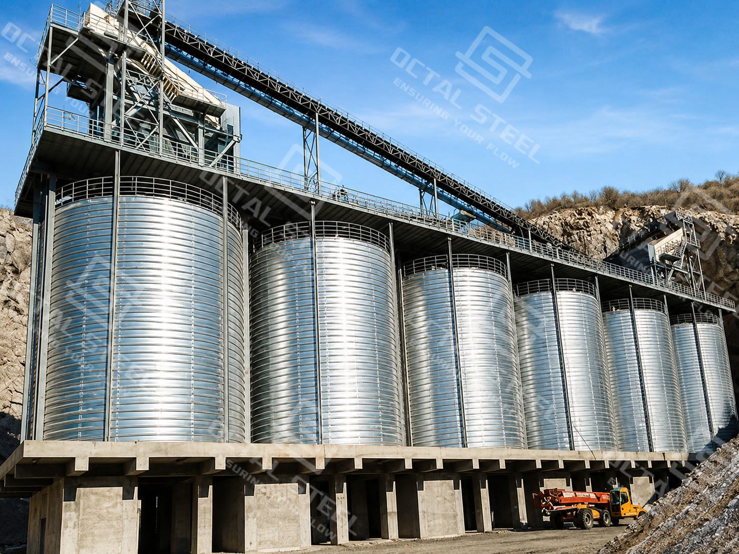
A lime steel silo can use spiral-formed, welded or bolted construction. The appropriate method depends on storage capacity, transportation restrictions, site access, erection sequence and equipment integration.
| Construction Type | Structural Characteristic | Lime-Service Consideration |
|---|---|---|
| Spiral-Formed Silo | Continuous steel coil forms the cylindrical wall on site | Continuous wall construction limits panel joints and supports large field-formed structures |
| Welded Silo | Steel plates or sections are joined by welding | Provides flexibility for custom hopper geometry, nozzles and equipment supports |
| Bolted Silo | Prefabricated panels are assembled with bolted joints | Joint sealing and panel alignment are critical for dust and moisture control |
| Insulated Silo | External insulation is protected by weather cladding | Limits internal condensation under large ambient-temperature changes |
| Shop-Fabricated Silo | Complete or sectional vessel is fabricated before transport | Transport dimensions and lifting capacity control the available size |
| Field-Erected Silo | Main shell and bottom are assembled at the installation site | Suitable for larger structures and restricted transport routes |
Download:Lime Silo Structure and System Interface Guide
Internal Surface
The internal surface of a lime silo should remain smooth through the main material-flow path. Weld projections, unsealed joints, internal brackets and abrupt section changes can retain fine lime and gradually create buildup, particularly around the hopper and outlet. Horizontal ledges should be minimized, while internal supports should be positioned away from the active flow zone or shaped to reduce material accumulation.
Moisture Sealing
The silo enclosure must maintain a continuous moisture barrier across the roof-to-shell joint, filling and venting nozzles, level-instrument connections, manholes, bolted joints, hopper transitions and flexible discharge connections. This is especially important for quicklime because contact with water, steam or humid process air can cause premature hydration, heat release and hardened deposits. Where the silo feeds a slaking system, the discharge interface must also prevent moisture and vapor from migrating back into the storage body.
External Protection
External protection is selected according to the site atmosphere and exposure conditions. The coating, galvanizing or combined protection system should cover the silo shell, roof, supports, platforms and external pipework, while instrument connections and replaceable components remain accessible for maintenance. Insulation and weather cladding may be added where temperature variation could cause internal condensation or affect filters, valves and level instruments.
Applications and Process Integration
A lime silo is normally connected to downstream dosing, slaking, mixing or dry-injection equipment. The discharge arrangement must match the lime form, required feed rate and process sequence.
- Water and Wastewater Treatment: Hydrated lime is discharged through a controlled feeder into a pre-wetting device or slurry preparation tank for pH adjustment, alkalinity control and water softening.
Process: Hydrated Lime Silo → Gravimetric Feeder → Pre-Wetting Device → Mixing Tank → Dosing Pumps - Quicklime Slaking: Pulverized or pebble quicklime is metered into a slaker, where controlled water addition produces hydrated lime slurry. The silo outlet must remain isolated from water, steam and humid process air.
Process: Quicklime Silo → Metering Feeder → Slaker → Grit Separation → Slurry Tank - Flue-Gas Treatment: Hydrated lime is supplied to a dry-injection line or slurry preparation system for acid-gas neutralization. Stable feed control limits reagent variation and downstream solids loading.
Process: Lime Storage Silo → Gravimetric Feeder → Dry Injection or Slurry Preparation → Gas-Treatment Reactor - Asphalt Production: Hydrated lime is weighed and transferred into the asphalt mixing process as a controlled dry additive. Enclosed feeding and conveying reduce dust around the weighing and transfer points.
Process: Hydrated Lime Silo → Screw or Rotary Feeder → Weigh Hopper → Enclosed Conveyor → Asphalt Mixer - Mining and Mineral Processing: Lime is used for pH control, flotation, leaching, process-water conditioning and tailings treatment. The silo may feed dry lime directly or supply a slaking and slurry distribution system.
Process: Bulk Lime Silo → Metering Feeder → Slaker or Mixing Tank → Process Distribution - Dry Mortar and Construction Materials: Hydrated lime is metered into a weigh hopper and added to a batch mixer. The feeder must follow the batching sequence to prevent material accumulation in inactive equipment.
Process: Lime Silo → Screw Feeder → Weigh Hopper → Batch Mixer
OCTAL STEEL Supply Scope and Advantages
OCTAL STEEL supplies the lime steel silo structure together with the interfaces required for filling, storage, discharge and downstream process integration.
| Supply Category | Available Scope |
|---|---|
| Silo Structure | Spiral-formed, welded or bolted steel silo body |
| Roof and Bottom | Steel roof with hopper-bottom or flat-bottom arrangement |
| Structural Support | Support frame, anchors and foundation load information |
| Filling and Venting | Filling nozzles, venting connections and silo-top filter interfaces |
| Instrument Interfaces | Connections for pressure, continuous-level and high-level instruments |
| Access System | Manholes, ladders, stairs and maintenance platforms |
| Flow Promotion | Connections for bin activators, aeration pads or controlled air injection |
| Discharge Interface | Isolation valve, outlet transition and feeder connection |
| Feeding Interface | Screw, rotary, volumetric or gravimetric feeder arrangement |
| Process Integration | Connections to slakers, mixers, weigh hoppers and conveyors |
| Surface Protection | Coating, galvanizing, insulation or weather cladding |
| Engineering Documents | General arrangement, equipment-interface drawings and foundation load data |
OCTAL STEEL’s advantage is the coordination of the silo structure and material-handling interfaces within one defined supply boundary. Spiral-formed, welded, bolted and insulated configurations can be selected according to lime behavior, storage capacity, transport limits and site erection conditions. Filling nozzles, roof equipment, hopper outlets, feeder transitions and downstream connections are defined before fabrication, reducing mismatched interfaces and site modification. Equipment identification, packing-list mapping and protected connection points also make receiving and installation easier to verify.
FAQ
Q1: How is lime silo capacity converted from cubic metres to tonnes?
A1: Use the silo’s usable volume and the settled bulk density of the specified lime. Freeboard and residual material are excluded from working capacity, while the shell, hopper and supports are checked using the higher density that may develop after consolidation.
Q2: Why can hydrated lime discharge suddenly after pneumatic filling?
A2: Pneumatic filling leaves air between the fine particles, temporarily making the powder more fluid. Controlled de-aeration, a correctly sized outlet and a metering feeder prevent the aerated lime from flooding the downstream process.
Q3: Can one lime silo store both hydrated lime and quicklime?
A3: Not without reviewing the complete configuration. Hydrated lime is fine and cohesive, while quicklime reacts with moisture. Sealing, hopper geometry, outlet size, flow promotion, feeder type and downstream connections may all require modification.
Q4: What must be confirmed before connecting a lime silo to a slaker or dosing system?
A4: Confirm the lime form, particle range, normal and peak feed rate, feeder accuracy, outlet head and interface elevation. Quicklime connections must also prevent water, steam and humid process air from migrating back into the silo.