Your Responsible Supplier Partner for Oil and Gas Products.

Spherical Tank
Recent Products


Rencent Articles





Spherical Tank
Storage media: LPG, propane, ammonia, hydrogen, oxygen, nitrogen, CO₂
Tank capacity: 400–10,000 m³ (reference designs)
Shell materials: Q345R, Q370R, 16MnDR, SA537 Class 2
Design standards: ASME Section VIII, GB/T 12337
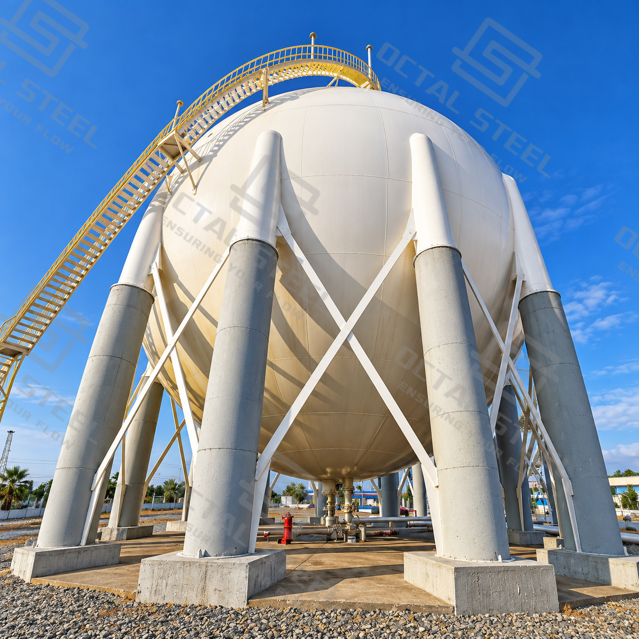
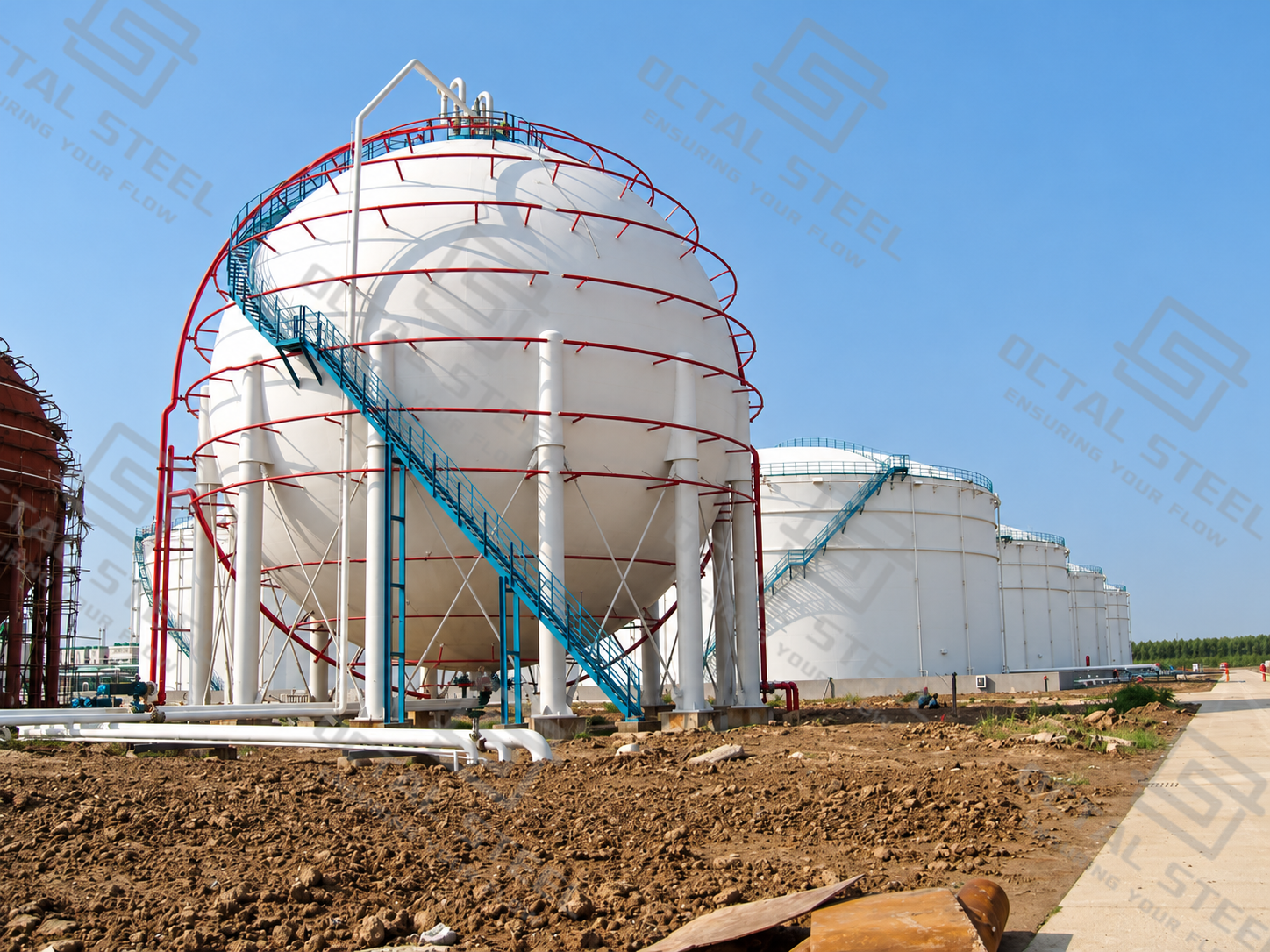
Structure: Spherical steel shell, support columns, bracing, nozzles and access platforms
A Spherical Tank is a welded steel pressure vessel designed for the storage of compressed gases and liquefied gases under controlled pressure and temperature conditions. Its pressure-retaining shell is assembled from precisely formed curved steel plates, typically supported by steel columns and bracing systems that transfer the combined loads of the vessel and its contents to the foundation. Unlike cylindrical vessels, a spherical shell develops approximately equal membrane stresses in all tangential directions under uniform internal pressure, allowing efficient use of shell material for large-capacity pressurized storage. Spherical tanks are commonly designed for LPG, propane, butane, propylene, liquid ammonia, hydrogen, oxygen, nitrogen, and other compatible industrial gases and chemicals.
Spherical tank specifications are determined by the stored medium, design pressure, minimum and maximum design temperatures, vessel diameter, material strength, corrosion allowance, and applicable pressure vessel code. Engineering reference projects include capacities from 400 to 10,000 m³, with shell materials such as Q345R, Q370R, 16MnDR, and SA537 Class 2 selected for different service conditions. Octal Steel supports spherical tank procurement with project-specific material selection, shell fabrication coordination, dimensional and welding quality requirements, and inspection documentation. Each vessel requires a verified design and defined fabrication and testing scope to ensure compatibility with its intended operating conditions.
Spherical Tank Specifications
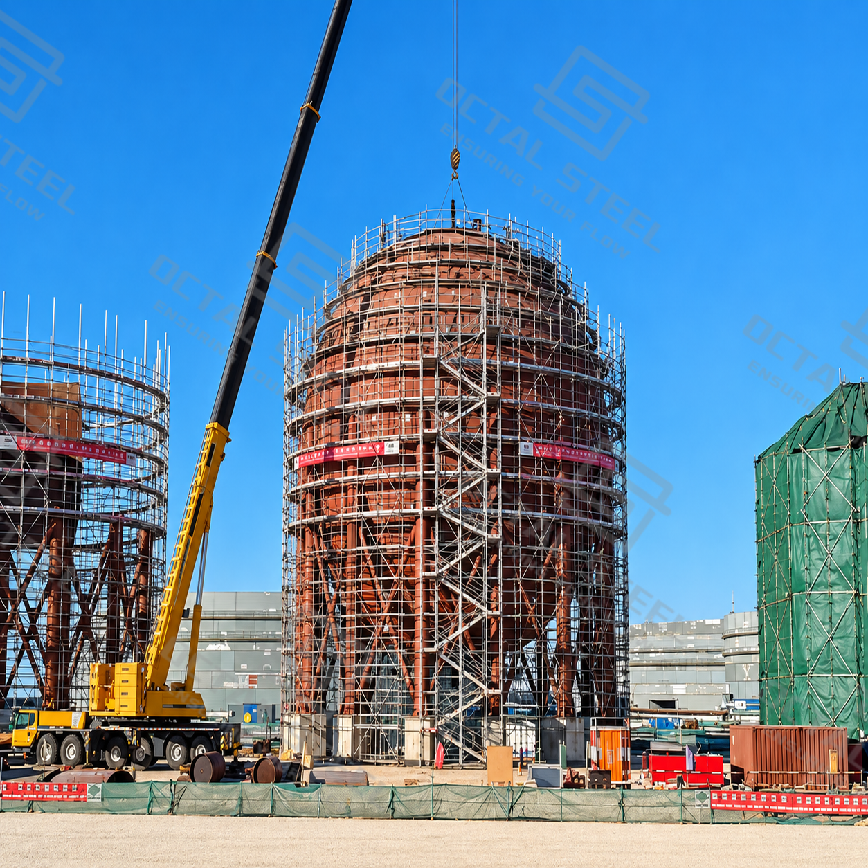
Spherical tanks are generally assembled from curved steel plates welded into a pressure-retaining shell. Large tanks commonly require sectional fabrication and field assembly because a complete spherical vessel cannot be transported economically or practically.
The following specifications illustrate the engineering parameters that must be defined before fabrication.
Spherical Tank Specifications
| Parameter | Specification / Design Consideration |
|---|---|
| Product | Spherical Tank / Sphere Tank |
| Construction | Welded spherical pressure vessel |
| Tank Capacity | Project-engineered; 400–10,000 m³ represented in selected reference designs |
| Shell Diameter | Approximately 9,200–26,800 mm in selected reference designs |
| Storage Media | LPG, propane, butane, propylene, ammonia, H₂, O₂, N₂, CO₂, and other compatible products |
| Design Pressure | Based on stored medium and operating conditions |
| Design Temperature | Defined by minimum and maximum design metal temperatures |
| Shell Materials | Carbon steel, low-alloy pressure-vessel steel, stainless steel, or qualified low-temperature steel |
| Design Codes | ASME Section VIII, GB/T 12337, or other project-applicable pressure-vessel standards |
| Structural Support | Steel columns with suitable bracing and foundation connections |
| Fabrication | Curved plate forming, edge preparation, welding, dimensional verification |
| Inspection | Material inspection, weld examination, dimensional checks, pressure and leak testing |
These values are not universal operating limits. The available tank capacity and dimensions depend on the design code, service conditions, material properties, transportation constraints, and construction capabilities.
Engineering Reference Specifications for Different Storage Media
The following table uses representative engineering data from spherical tank construction projects to show how design parameters change with the stored medium.
| Storage Medium | Capacity (m³) | Design Pressure (MPa) | Design Temperature (°C) | Shell Material | Nominal Shell Thickness (mm) |
|---|---|---|---|---|---|
| LPG | 3,000 | 1.77 | 0 to 60 | Q345R | 46 |
| Oxygen | 2,000 | 3.15 | -19 to 50 | 07MnMoVR | 51 |
| Liquid CO₂ | 1,000 | 2.20 | -30 to 50 | 16MnDR | 42 |
| Liquid Ammonia | 2,000 | 2.50 | -19 to 50 | Q370R | 54 |
| Butane | 4,000 | 0.79 | -19 to 50 | Q370R | 24 |
| Propylene | 3,000 | 2.16 | -19 to 50 | Q370R | 54 |
| Hydrogen | 400 | 2.00 | -19 to 55 | Q345R | 34 |
| Nitrogen | 2,000 | 3.15 | -20 to 60 | SA537 Class 2 | 56 |
The data are examples from separate engineering projects, not standardized Octal Steel stock specifications. Thickness values apply to the particular designs shown and should not be transferred to another tank without calculation.
The difference between a 24 mm butane vessel and a 54 mm propylene vessel cannot be explained by the product name alone. Shell diameter, design pressure, allowable material stress, weld-joint efficiency, corrosion allowance, and temperature-dependent material properties all influence the required thickness.
For a new project, the design is therefore developed from the storage duty first, followed by the pressure boundary, material selection, and structural analysis.
Why Are Spherical Tanks Used for Pressurized Storage?
Spherical tanks are widely used for pressurized gas and liquefied gas storage because their round shape distributes internal pressure evenly across the tank shell. Unlike cylindrical tanks, which experience different levels of stress in different directions, a spherical vessel has a more uniform stress distribution. This allows the steel shell to resist internal pressure efficiently, making spherical tanks suitable for storing large quantities of LPG, propane, ammonia, and industrial gases.
Another advantage is that a sphere requires less surface area to enclose the same volume than other tank shapes. This can reduce the amount of steel needed for the pressure-retaining shell. However, the actual material requirement also depends on the design pressure, tank diameter, steel grade, and required wall thickness.
The main advantages of spherical tanks include:
Uniform Pressure Distribution: Internal pressure acts evenly on the curved shell, reducing differences in stress across the main shell structure.
Efficient Material Use: The spherical shape provides a favorable balance between storage capacity and the amount of steel required for pressure containment.
Large Storage Capacity: Spherical tanks can accommodate substantial volumes of pressurized gases and liquefied products in a single vessel.
Structural Efficiency: The absence of flat shell surfaces and the uniform curvature help the vessel resist internal pressure, although support connections, nozzles, and welded joints still require detailed engineering design.
These advantages make spherical tanks a practical choice for large pressurized storage facilities. Nevertheless, curved steel plate forming, specialized welding, and on-site assembly make their construction more demanding than conventional cylindrical tanks. The final tank design must balance pressure requirements, storage volume, material costs, and installation conditions.
Spherical Tank vs. Cylindrical Storage Tank
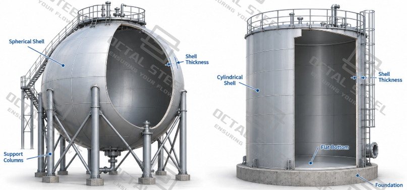
A spherical tank is not automatically cheaper or safer than a cylindrical tank. The geometry can reduce the pressure-induced shell 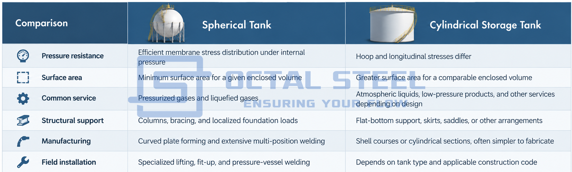
material requirement, but curved plate forming, site welding, scaffolding, access, inspection, and construction time can increase the installed cost.
For large volumes stored near atmospheric pressure, cylindrical storage tanks are often more economical. Spheres are most attractive when the required pressure containment and storage conditions justify their more demanding construction.
Download:spherical tank design material selection guide.pdf
Spherical Tank Design Standards
The governing standard determines how the vessel is calculated, fabricated, inspected, pressure-tested, and documented. The standard must be selected before finalizing the shell thickness or approving the manufacturing drawings.
| Standard / Regulation | Relevance to Spherical Tanks |
|---|---|
| ASME BPVC Section VIII, Division 1 | Pressure-vessel design, fabrication, examination, and testing under its applicable rules |
| ASME BPVC Section VIII, Division 2 | Alternative pressure-vessel rules including more detailed design and analysis provisions |
| GB/T 12337 | Chinese standard for steel spherical tanks within its applicable scope |
| GB/T 150 series | General pressure-vessel requirements where invoked by the governing design framework |
| PED 2014/68/EU | European regulatory conformity requirements for pressure equipment within its scope |
| ASME Section IX | Qualification of welding procedures and welding personnel |
| ASME Section V | Nondestructive examination methods when referenced by the applicable construction rules |
| API 2510 | LPG installation requirements relevant to the overall storage facility, rather than a substitute for the pressure-vessel construction code |
An ASME-designed sphere must follow the designated edition, division, material rules, inspection requirements, and authorized certification route. Specifying an ASME standard in the purchase order does not, by itself, establish that the fabricator is authorized to apply an ASME certification mark.
For European projects, PED conformity also requires the applicable conformity assessment procedure and supporting technical documentation. The pressure-vessel design code and regulatory approval requirements must be coordinated rather than treated as interchangeable.
Types of Spherical Tanks
Spherical tanks can be categorized by stored medium, operating temperature, material, and pressure service. For industrial procurement, classification by storage medium and design conditions is generally more useful than classification by appearance.
LPG and Spherical Propane Tanks
An LPG spherical tank stores liquefied petroleum gas under pressure at a temperature corresponding to the storage and operating conditions. The design must consider vapor pressure, liquid filling limits, temperature variation, relief-system capacity, and the composition of propane and butane mixtures.
A 3,000 m³ LPG sphere documented in the engineering reference uses a design pressure of 1.77 MPa, Q345R shell material, and a nominal shell thickness of 46 mm.
This example illustrates a pressurized liquid-gas storage application, but the same pressure and thickness should not be assumed for every propane or LPG composition.
Industrial Gas Spherical Tanks
Oxygen, nitrogen, hydrogen, and other industrial gases may be stored in spherical vessels where the capacity and pressure conditions make this configuration suitable.
Gas service requires attention to pressure cycling, material compatibility, leakage prevention, and the operating process. Oxygen service also requires stringent cleanliness and control of ignition hazards. Hydrogen service requires specific consideration of material compatibility, hydrogen-related degradation mechanisms, and leak-tightness.
A representative 2,000 m³ oxygen sphere in the engineering documentation has a design pressure of 3.15 MPa and a 51 mm shell made from 07MnMoVR.
Liquid Ammonia and Chemical Spherical Tanks
Liquid ammonia storage involves pressure containment, toxicity control, material selection, and inspection requirements associated with the particular service.
A documented 2,000 m³ ammonia sphere uses Q370R steel, a 2.5 MPa design pressure, and 54 mm nominal shell thickness.
Other chemical storage applications include propylene, butadiene, pentane, dimethyl ether, and vinyl chloride monomer. Each medium introduces different considerations involving vapor pressure, minimum design temperature, corrosion, product contamination, or chemical stability.
Materials and welding procedures must therefore be qualified for the intended stored product rather than selected solely from a general carbon-steel specification.
Low-Temperature and Special-Service Spherical Tanks
Special spherical vessels can be designed for refrigerated gases, liquid CO₂, low-temperature process conditions, or other demanding services.
These applications may require low-temperature pressure-vessel steels, impact testing, insulation, temperature-control systems, and additional thermal stress analysis.
For example, a documented 1,000 m³ liquid CO₂ sphere uses 16MnDR steel with a design temperature from -30°C to 50°C.
Cryogenic storage is a separate design challenge. An LNG or liquid-hydrogen sphere intended for deeply refrigerated service cannot be treated as a conventional ambient-temperature LPG sphere with insulation added afterward. The complete pressure boundary, thermal insulation, boil-off management, supports, and material system require an appropriate dedicated design.
Spherical Tank Structure and Design Considerations
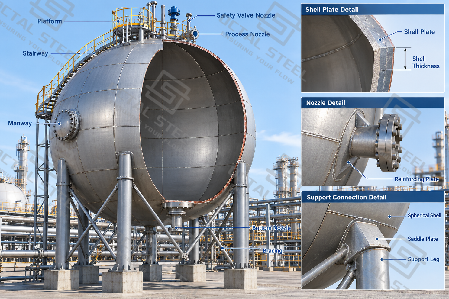
The pressure-retaining shell is only one part of a spherical tank. Supports, openings, piping loads, operating accessories, and the foundation all affect the structural behavior of the complete installation.
Spherical Shell and Plate Arrangement
The shell consists of curved steel plates arranged into a continuous spherical surface. Equatorial, upper, and lower shell sections are joined by welded seams.
The plate layout affects fabrication accuracy, weld length, lifting arrangements, and site assembly. Plate curvature must match the design radius closely enough to maintain acceptable joint fit-up without excessive corrective force.
Out-of-roundness, local flattening, and misalignment can introduce bending stresses not represented by ideal membrane theory. These effects become particularly important near welded attachments and shell discontinuities.
Support Columns and Bracing
Large spherical tanks are typically elevated on multiple steel columns connected to the shell near the equatorial region. Bracing between columns provides lateral stability against horizontal actions.
The support system transfers tank self-weight, stored-product weight, and environmental loads into the foundation. The design must consider wind, seismic actions, thermal movement, and local loads at the shell-to-column connections.
Column alignment, anchor bolt positioning, and foundation elevations are checked during erection. Support loads and local shell stresses also need evaluation because the ideal spherical membrane-stress relationship does not describe these locations adequately.
Nozzles, Manholes, and Reinforcement
Inlet and outlet nozzles, vapor connections, relief-system connections, drains, and instrument openings interrupt the spherical pressure boundary.
Each opening requires an appropriate reinforcement assessment under the governing design rules. Nozzle loads from connected piping can add local forces and moments that are not captured by internal-pressure calculations alone.
Manholes provide access for internal examination and maintenance. Their dimensions, reinforcement details, and position must satisfy the applicable construction requirements and the access needs of the project.
Spherical Tank Materials and Shell Thickness
Shell material selection must satisfy the design temperature, pressure, allowable stress, weldability, required toughness, and compatibility with the stored product.
Pressure-vessel steels used in different engineering projects include Q345R, Q370R, 16MnDR, SA537 Class 2, and specialized higher-strength or low-temperature grades.
| Material | Engineering Consideration |
|---|---|
| Q345R | Pressure-vessel steel used in appropriate temperature and pressure applications |
| Q370R | Higher-strength pressure-vessel steel where permitted by the selected design rules |
| 16MnDR | Low-temperature pressure-vessel steel for applications requiring suitable low-temperature toughness |
| SA537 Class 2 | Heat-treated pressure-vessel steel used where its strength and toughness properties meet the design requirements |
| S30408 | Austenitic stainless steel for suitably qualified corrosion or process-service applications |
| 07MnNiMoDR | Specialized low-temperature pressure-vessel steel requiring grade-specific design and fabrication verification |
The specified material must match the applicable code’s permitted material designation and product form. Similar mechanical strength values do not automatically make two steel grades interchangeable.
How Is Spherical Tank Shell Thickness Determined?
Shell thickness is established by pressure-vessel design calculations rather than the nominal tank capacity alone.
The calculation considers design pressure, sphere diameter, allowable material stress at design temperature, weld-joint efficiency, and relevant code coefficients. Additional requirements may arise from corrosion allowance, external pressure, local reinforcement, support loading, and fabrication tolerances.
A larger tank can require a thicker shell at the same pressure, while a stronger permitted material may reduce the pressure-required thickness. However, minimum thickness limitations, low-temperature toughness, welding requirements, and local stress conditions can govern the final selection.
The difference between specified nominal plate thickness and minimum acceptable finished thickness must also be controlled during fabrication. Plate forming, manufacturing tolerances, and applicable material standards influence the thickness available in the completed shell.
Spherical Tank Manufacturing Process
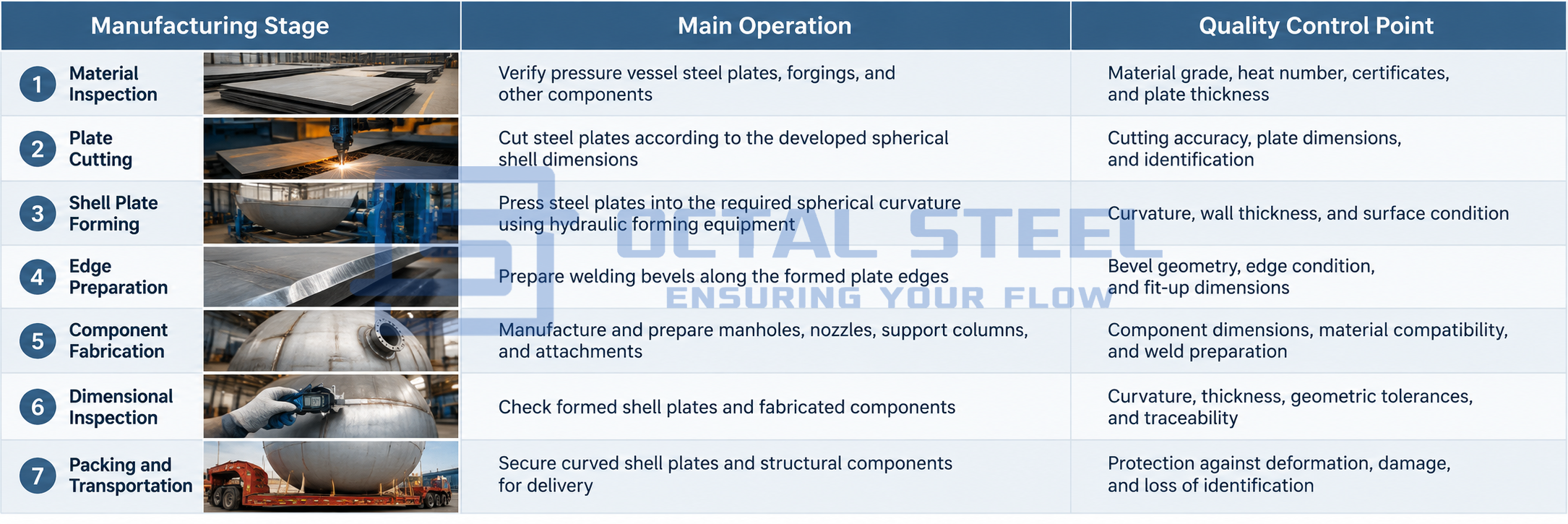
The manufacturing of a spherical tank involves steel plate preparation, precision forming, component fabrication, and dimensional inspection. Since large spherical tanks are usually assembled on-site, the steel shell plates must be accurately formed and inspected before transportation. Particular attention is given to plate curvature, wall thickness, weld preparation, and dimensional accuracy, as these directly affect shell alignment and welding quality during installation.
The manufacturing process generally follows these stages:
Cold Forming of Spherical Shell Plates
Cold forming is one of the most important operations in spherical tank fabrication. Flat steel plates are progressively pressed into curved shell segments using hydraulic presses and specially designed forming dies. For thick plates, multiple pressing operations may be required to achieve the specified spherical curvature while controlling deformation and local thickness reduction.
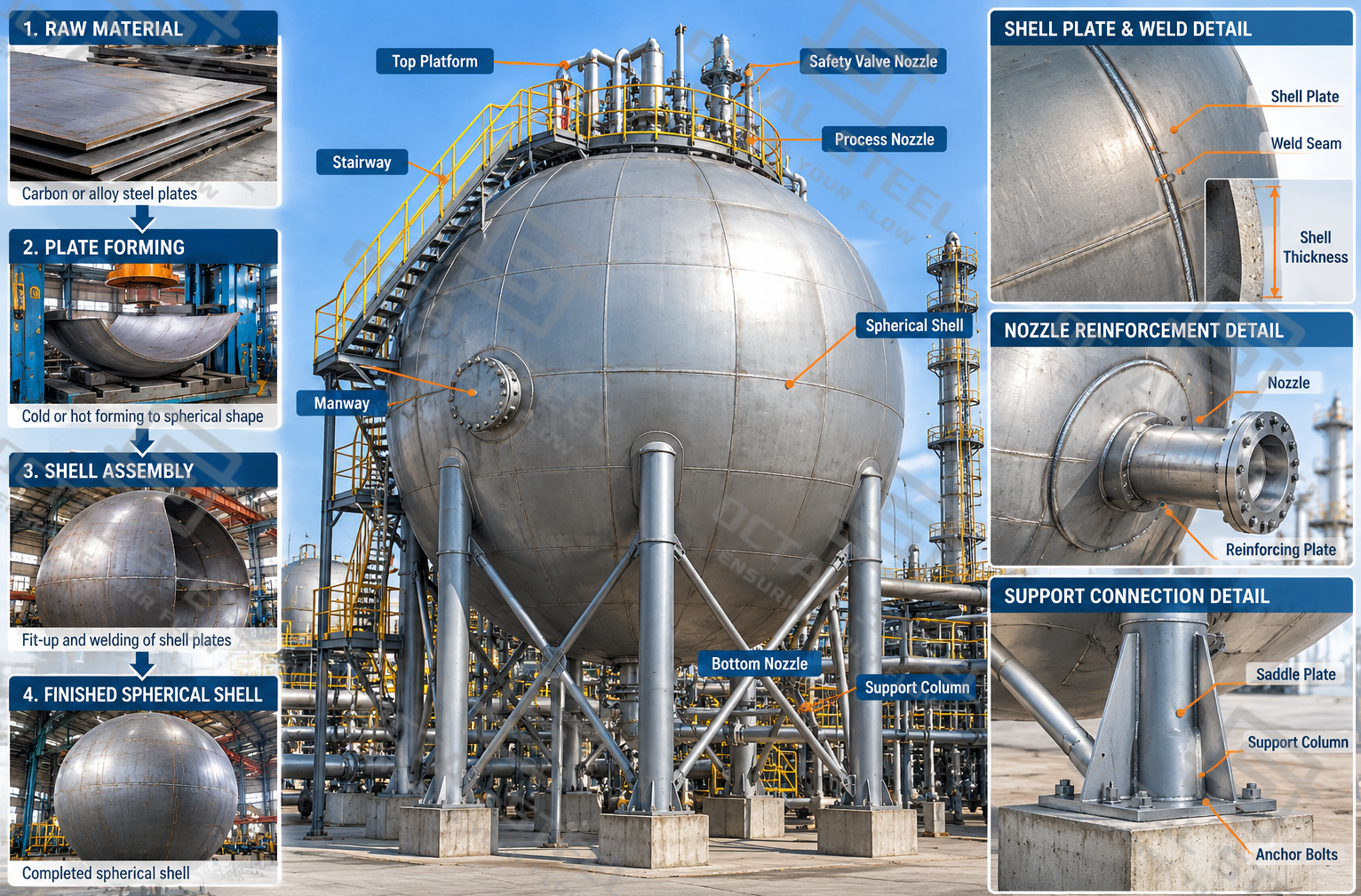
The forming sequence generally includes initial pressing, profile cutting, and precision pressing. After forming, the shell plates undergo dimensional inspection to verify their curvature, thickness, edge geometry, and overall shape. These checks help ensure that adjacent plates can be accurately aligned during field assembly.
For heavy-wall spherical tanks, forming procedures may also require additional verification of yield strength, tensile strength, impact toughness, metallographic structure, and residual stress. Such testing helps assess whether the forming process has affected the material properties required for pressure vessel service.
Accurate plate forming reduces joint misalignment, excessive weld gaps, and corrective work during installation. It also helps maintain the intended spherical geometry of the completed pressure vessel.
Spherical Tank Field Erection and Welding
The field installation sequence must be planned around foundation readiness, shell plate identification, lifting operations, alignment, welding access, and inspection hold points.
A typical site-erection sequence involves foundation acceptance, receipt of shell components, installation of supports, lifting and positioning of curved plates, joint fit-up, welding, examination, and final testing.
Foundation and Support Installation
The foundation is checked against the approved civil drawings before heavy components are erected. Anchor locations, levels, and support geometry must be compatible with the tank structure.
Support columns are positioned and aligned according to the erection plan. Temporary restraints or construction bracing may be needed before the completed tank develops its intended structural stability.
Shell Assembly and Alignment
In one established erection approach, the equatorial region is assembled first, followed by upper and lower shell sections.
The shell plates are lifted into position using approved lifting points and temporary support arrangements. Joint alignment and root openings are checked before welding.
Forced fit-up should be controlled because excessive correction can leave unintended assembly stress or cause local distortion.
Welding and Heat Treatment
Spherical tank construction involves welding in horizontal, vertical, and overhead positions. The welding process, consumables, preheat, interpass-temperature limits, and any post-weld heat treatment must follow qualified procedures.
Commonly applicable welding processes include shielded metal arc welding and other qualified manual, mechanized, or semi-automatic processes.
Preheat and post-weld heat treatment are not universally required for every spherical tank. Their applicability depends on the material, governing code, welded thickness, service conditions, and approved fabrication specification.
Where overall post-weld heat treatment is required, temperature distribution and the heating cycle must be controlled and documented.
Quality Control, Inspection, and Pressure Testing
Quality control for spherical tanks covers material verification, shell dimensions, weld integrity, and pressure tightness. Inspections are performed during fabrication and field erection according to the applicable pressure vessel code and approved Inspection and Test Plan (ITP).
| Inspection Item | Inspection Method | Acceptance Requirements |
|---|---|---|
| Material Inspection | Material certificates, heat number and thickness verification | Approved material specifications |
| Dimensional Inspection | Shell curvature, wall thickness, plate alignment and weld fit-up | Approved drawings and dimensional tolerances |
| Weld Inspection | Visual inspection, RT/UT and MT/PT where required | Applicable code and specified NDT coverage |
| Heat Treatment | Temperature monitoring and recorded heating cycles | Approved PWHT procedure, where required |
| Hydrostatic Testing | Controlled water pressure test | Test pressure and acceptance criteria per design code |
| Leak Testing | Gas-tightness verification where specified | Approved test procedure and leakage acceptance criteria |
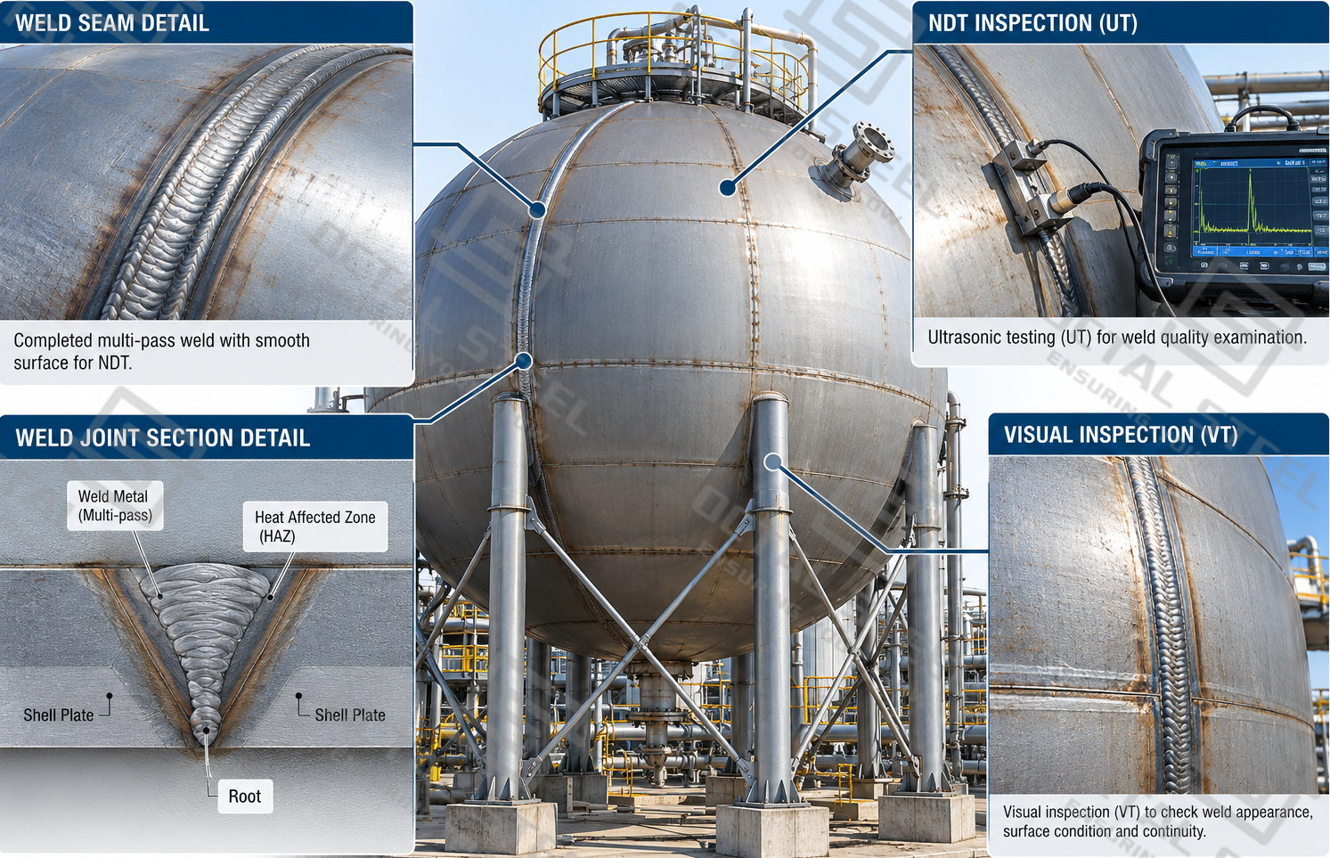
Weld Inspection and Traceability
Non-destructive testing (NDT) is used to identify surface and internal weld defects without damaging the vessel. Radiographic testing (RT) and ultrasonic testing (UT) examine weld integrity, while magnetic particle testing (MT) and penetrant testing (PT) detect applicable surface defects. Testing methods and coverage follow the governing code and project requirements.
Material heat numbers, welding records, NDT reports, and applicable heat-treatment records are maintained to support traceability.
Hydrostatic and Leak Testing
After fabrication and welding inspections, the spherical tank undergoes hydrostatic testing at the pressure specified by the applicable design code. The test verifies pressure-boundary integrity, with consideration given to temporary water loads on the supports and foundations.
Leak testing may also be performed to check the tightness of welded joints, connections, and installed components. Test pressure, medium, and acceptance criteria follow the approved procedure.
Applications of Spherical Storage Tanks
Spherical tanks are used where a storage facility requires significant pressurized inventory and the spherical configuration suits the product, operating cycle, and site conditions.
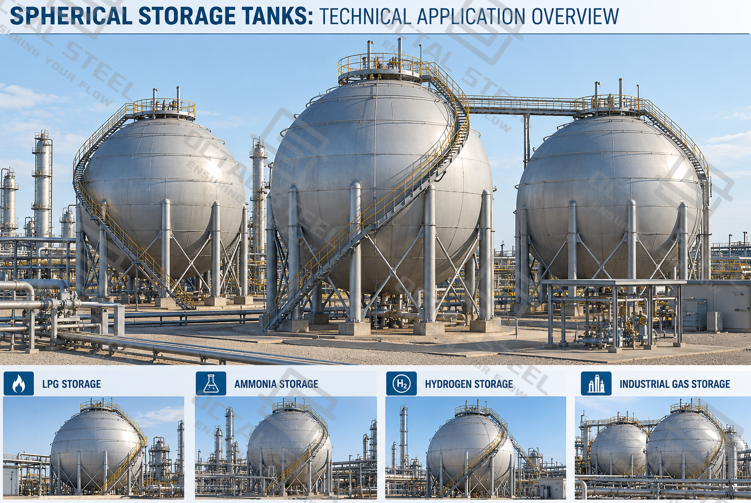
LPG Storage and Distribution Terminals
At a bulk LPG terminal, incoming propane or butane-rich product is transferred into pressurized storage before being dispatched to downstream users. The sphere must accommodate operating temperature changes, vapor-pressure variation, filling control, relief protection, and the required withdrawal rate.
Petrochemical Intermediate Storage
During propylene, butadiene, or other chemical processing operations, spherical vessels can provide storage capacity between production and downstream processing units. Product-specific material compatibility, contamination control, relief-system design, and process-piping interfaces must be addressed.
Industrial Gas Supply Facilities
Oxygen or nitrogen spheres may be used as pressure-storage equipment in selected industrial gas systems. The design must be coordinated with compression, distribution, pressure regulation, and site safety arrangements. Oxygen-service cleanliness and materials compatibility are particularly important.
Ammonia Storage Facilities
In chemical and fertilizer production, liquid ammonia spheres support pressurized inventory management. Toxic release prevention, suitable material selection, overpressure protection, inspection accessibility, and emergency isolation arrangements are essential parts of the overall installation.
Hydrogen Storage and Process Buffering
Spherical hydrogen vessels can provide process-storage or buffer capacity at specified pressure conditions. Hydrogen compatibility, pressure cycling, material performance, connections, and leak detection require evaluation as part of the complete storage system.
Download:spherical tank fabrication erection inspection guide.pdf.
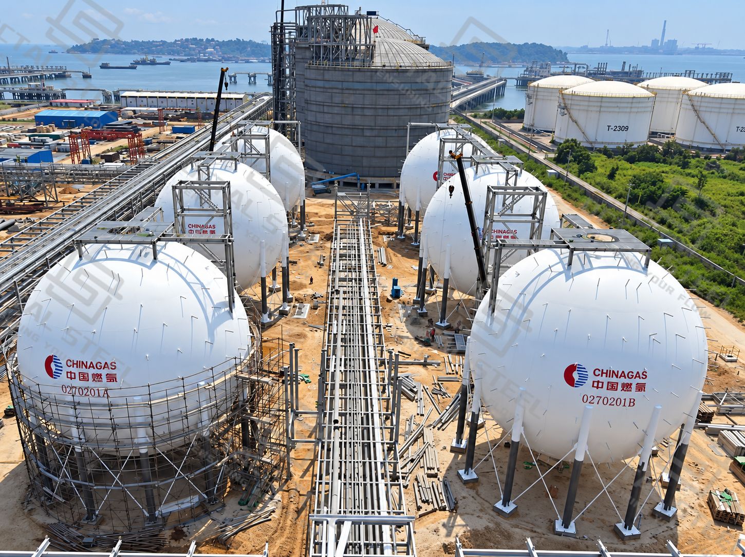
Why Choose Octal Steel for Spherical Tank Projects?
Octal Steel supports spherical tank projects from technical specification review and material selection to fabrication coordination, quality inspection, and international delivery. With experience in steel products and oil and gas project supply, we understand the requirements of large pressure vessels, including shell material compatibility, welding quality, dimensional accuracy, and installation coordination.
For large spherical tanks, curved shell plates, support structures, nozzles, and other components can be prepared for transportation and subsequent field assembly. Particular attention is given to material traceability, fabrication dimensions, inspection records, and protective packaging to reduce damage and assembly difficulties during shipment and installation.
We work with customers to clarify technical requirements, coordinate suitable manufacturing arrangements, and prepare the necessary documentation according to the agreed project scope. Our focus is on providing reliable technical support, consistent quality control, and practical delivery solutions throughout the project.
FAQ
What is a spherical tank?
A spherical tank is a pressure vessel with a spherical shell used to store gases or liquefied products under specified pressure and temperature conditions. Its geometry distributes internal-pressure membrane stresses efficiently.
Why is LPG stored in spherical tanks?
The spherical geometry is efficient for containing internal pressure and offers a relatively low surface-area-to-volume ratio. For large pressurized LPG inventories, these advantages can justify the additional forming and field-welding requirements.
Why are LNG tanks spherical?
Some specialized LNG containment systems use spherical geometry, but many large onshore LNG storage installations use insulated cylindrical tanks. The appropriate configuration depends on storage temperature, pressure, capacity, insulation, and containment requirements.
What information is needed to order a spherical tank?
The main requirements include storage medium and composition, capacity, design pressure, design temperature, governing code, installation location, material requirements, corrosion allowance, nozzle connections, inspection scope, and delivery boundary.