Your Responsible Supplier Partner for Oil and Gas Products.

Globe Valve
Recent Products



Rencent Articles







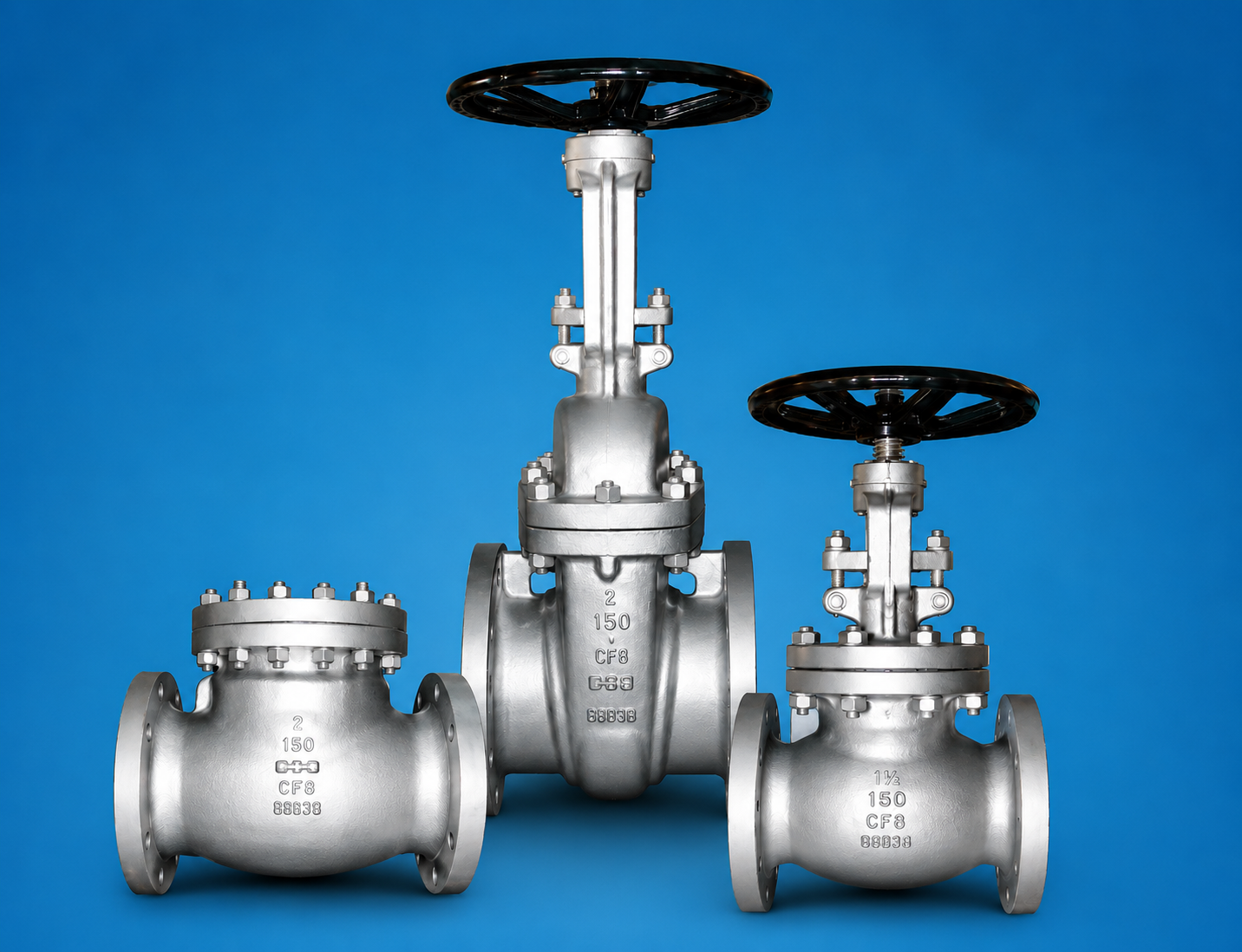
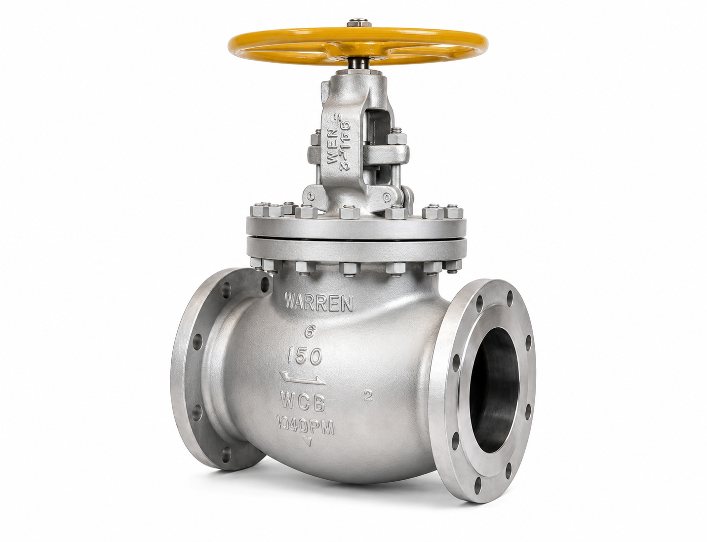
Globe Valve
Valve Types: Cast steel, forged steel, pressure seal, bellows seal and angle globe valves
Size Range: DN15–DN600 / NPS 1/2–24, depending on configuration
Pressure Range: PN10–PN420 / Class 150–2500
Materials: Carbon steel, alloy steel and stainless steel with service-selected trim
End Connections: Flanged or butt-welded
Operation: Manual, electric, pneumatic or hydraulic
Globe valve uses a cast or forged steel pressure-containing body with a stem-driven disc or plug, stationary seat ring and service-selected trim to regulate or isolate flow in industrial piping. Handwheel, gearbox or actuator input produces linear stem travel, progressively changing the disc-to-seat opening during throttling and bringing the seating surfaces into contact for shutoff; this controlled restriction provides effective flow and pressure regulation, while the indirect internal passage creates a higher pressure drop than straight-through isolation valves. Body pattern, pressure class, bonnet construction, trim materials and operating conditions therefore need to be evaluated together for refinery, petrochemical, steam, utility and other process services.
Steel globe valves can be configured with cast or forged bodies, conventional or pressure-seal bonnets, different trim systems and T-pattern, Y-pattern or angle flow passages. Carbon steel, alloy steel and stainless steel globe valve constructions can be matched to pressure-temperature conditions, process medium, corrosion exposure and required throttling duty.
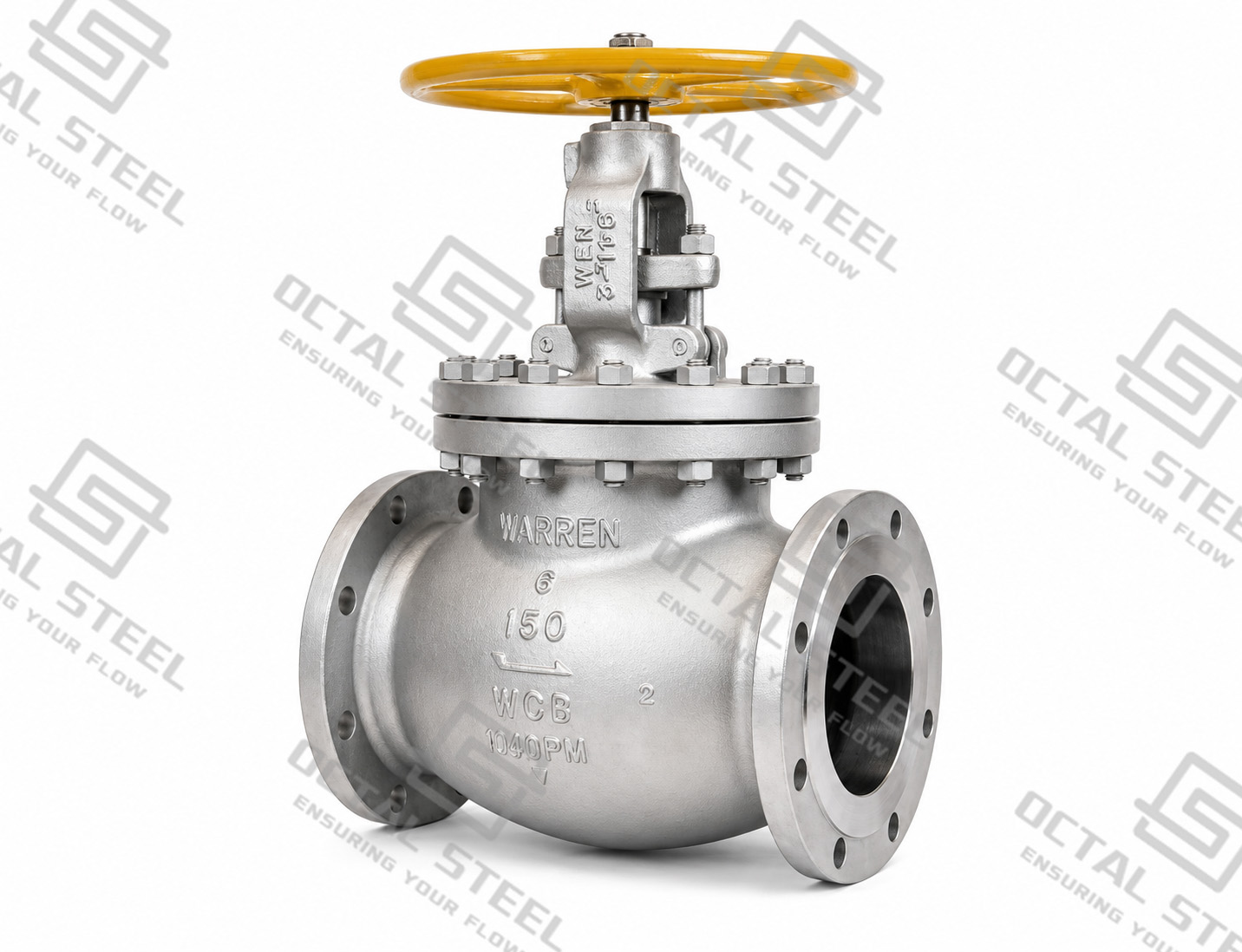
Industrial Globe Valve Product Range
The product range covers conventional cast steel globe valves, compact forged steel globe valves and pressure-seal configurations. The supplied product data gives the following reference ranges. Final size and pressure-class availability should be confirmed together with the selected material, design standard, end connection and operating method.
| Globe Valve Configuration | Reference Size Range | Pressure Designation Range | Main Materials | End Connections | Operation |
|---|---|---|---|---|---|
| Forged Steel Globe Valve | DN15–DN100 / NPS 1/2–4 | PN10–PN420 / Class 150–2500 | Carbon steel, alloy steel, stainless steel | Flanged, butt-welded | Manual, electric, pneumatic, hydraulic |
| Cast Steel Globe Valve | DN50–DN400 / NPS 2–16 | PN10–PN250 / Class 150–1500 | Carbon steel, alloy steel, stainless steel | Flanged, butt-welded | Manual, electric, pneumatic, hydraulic |
| Pressure Seal Globe Valve | DN50–DN600 / NPS 2–24 | PN10–PN420 / Class 150–2500 | Carbon steel, alloy steel, stainless steel | Flanged, butt-welded | Manual, electric, pneumatic, hydraulic |
The PN and ASME Class values in the table are separate pressure designation systems; they should not be interpreted as direct numerical equivalents. Actual pressure-temperature capability is established from the governing valve standard, material group, pressure class and design temperature.
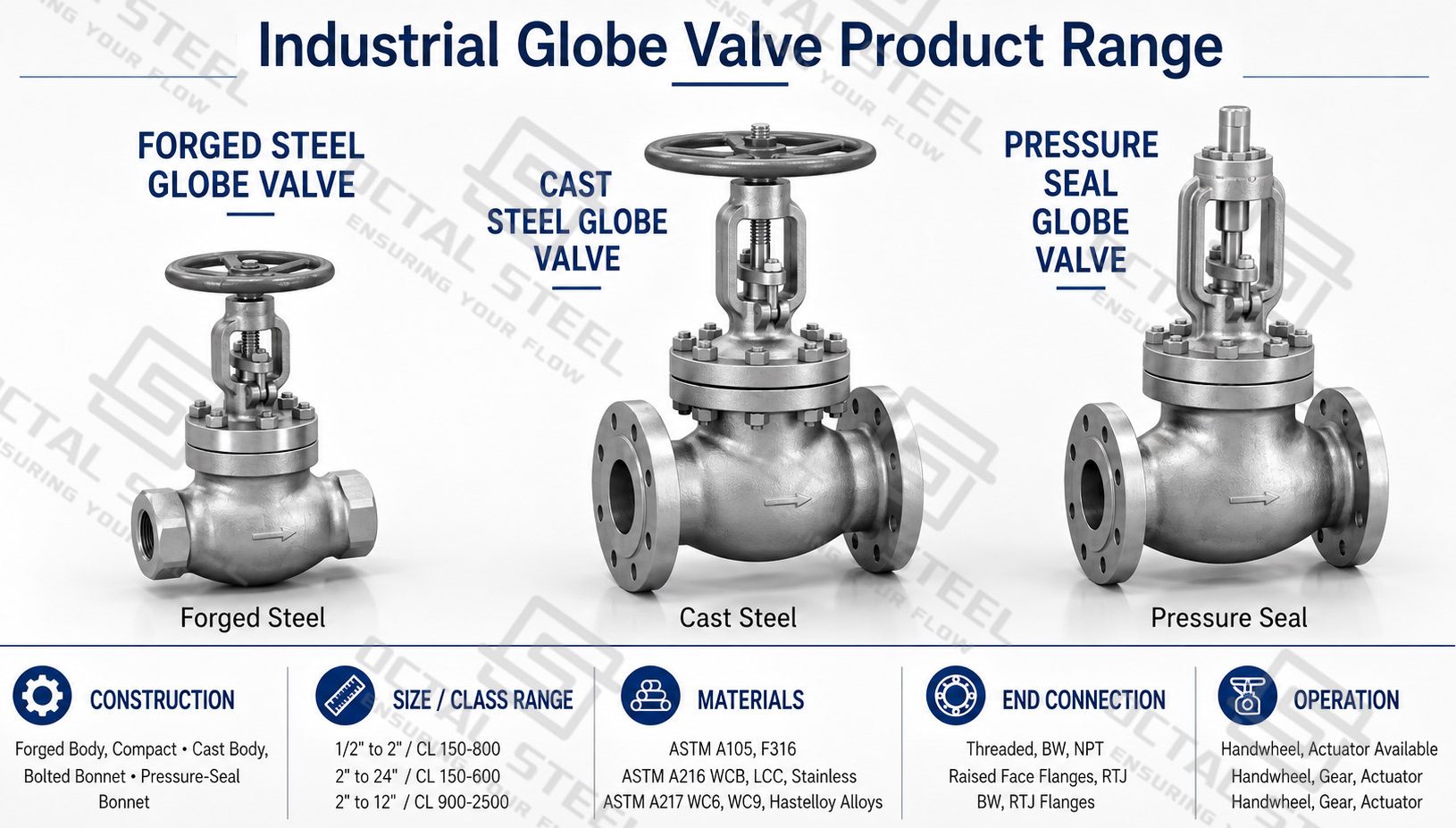
The three ranges also represent different construction routes. Forged bodies are particularly relevant to compact valve construction, while cast bodies accommodate larger and more complex pressure-containing geometries. Pressure-seal construction extends the configuration options for projects where a pressure-assisted bonnet joint is specified.
How a Globe Valve Works
Manual operation starts at the handwheel. Rotation is converted into linear stem travel, moving the disc toward or away from the stationary seat. When the disc rises, the effective flow area around the seat increases. Lowering the disc reduces that area until the seating surfaces meet and establish shutoff.
The important hydraulic action occurs around the disc-seat restriction. In a partially open position, the fluid is forced through a relatively small opening and changes direction through the valve body. Local velocity and turbulence increase around the trim while pressure decreases across the restriction. This relationship between disc position and effective flow area is why a globe valve can regulate intermediate flow much more effectively than a conventional gate valve.
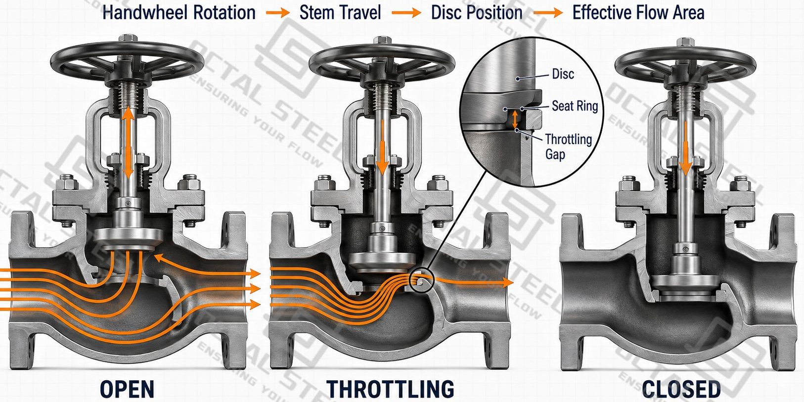
The same mechanism explains one of its principal engineering trade-offs. Even when fully open, the fluid still follows an indirect path through a conventional globe-valve body, so pressure loss remains higher than through a straight-through isolation valve. Allowable pressure drop therefore belongs in the valve-selection calculation rather than being treated as an afterthought.
Flow direction should follow the manufacturer’s marking and the approved project specification. Differential pressure acting above or below the disc changes the hydraulic load on the closure member and can affect operating thrust and seating behavior.
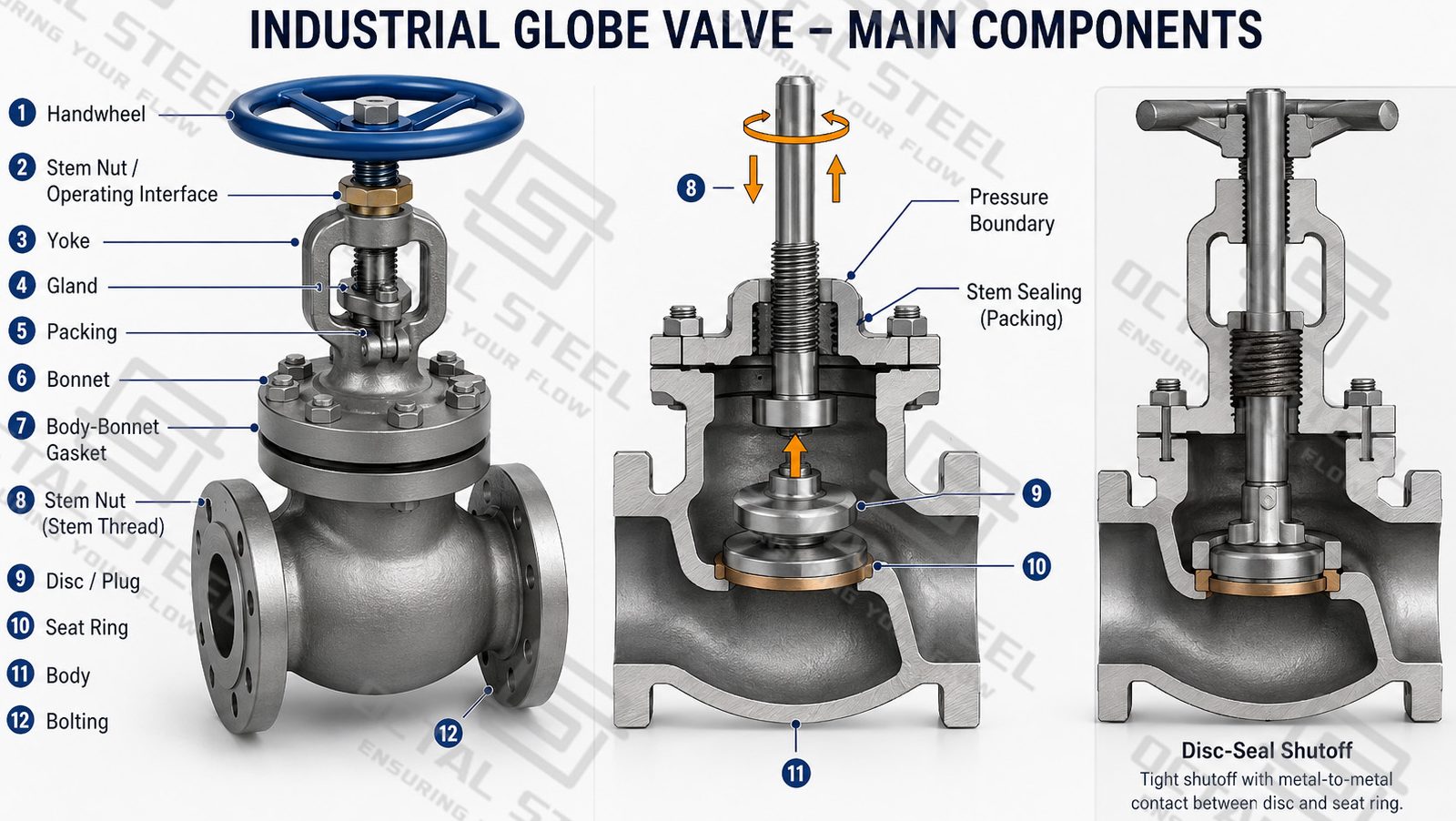
Globe Valve Main Components
The operating performance of a steel globe valve depends on the alignment and interaction of the pressure boundary, stem and trim rather than on the body material alone.
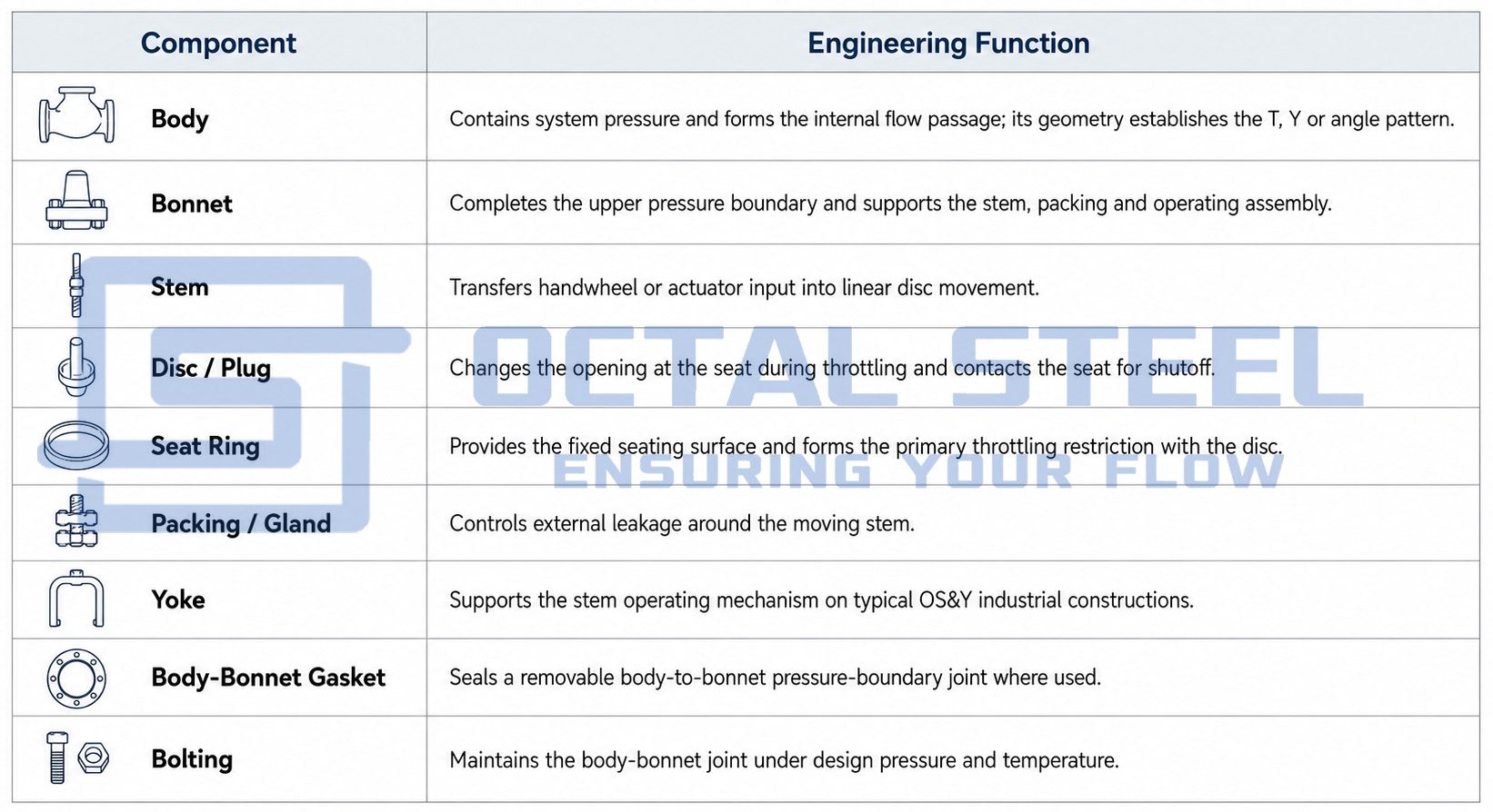
Disc and seat alignment is particularly important. As the two surfaces approach during throttling, flow velocity and turbulence increase around the restriction. Erosion, corrosion, galling or a small leakage path can progressively damage the seating surfaces and reduce shutoff performance, making trim design and seat finishing important manufacturing controls.
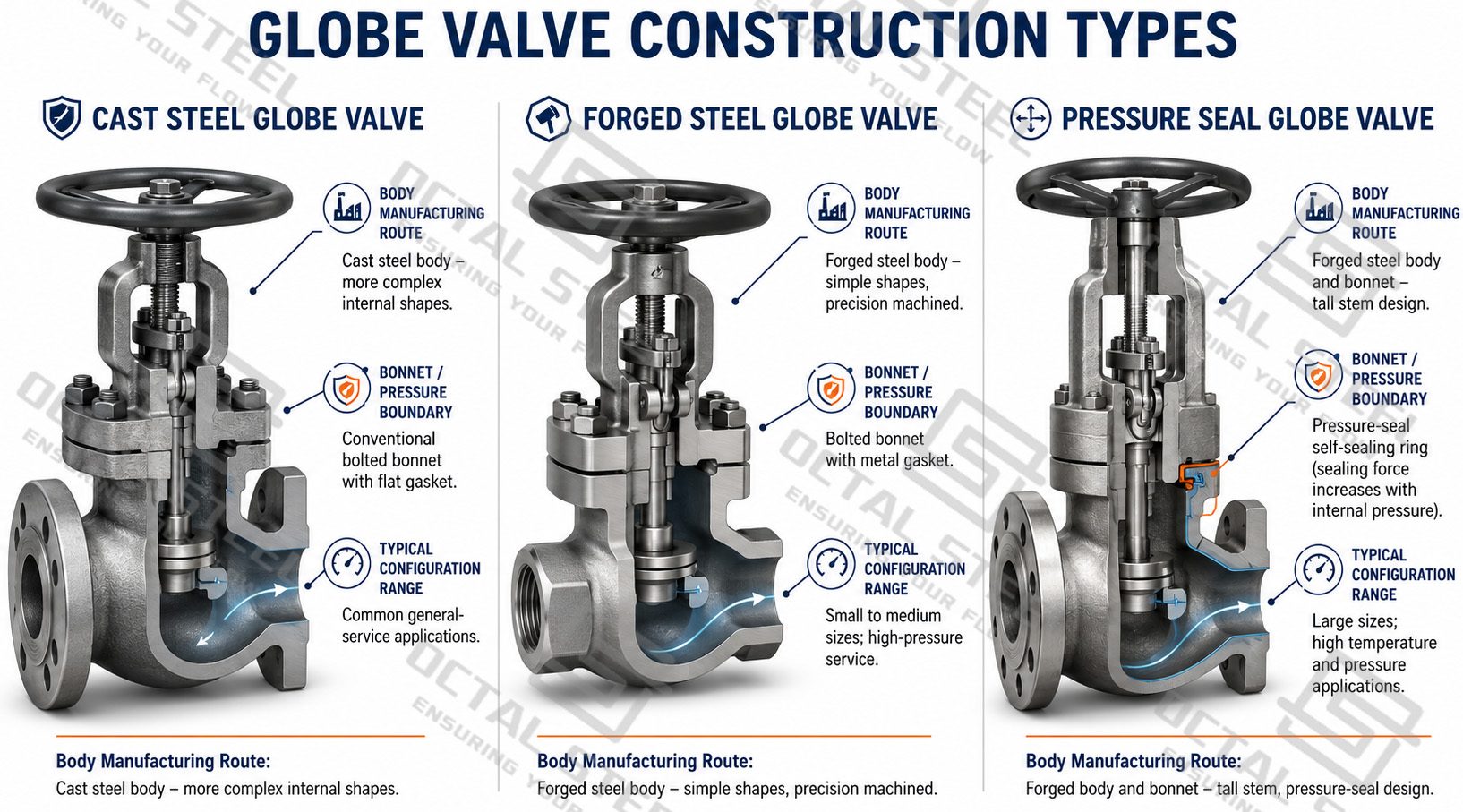
Cast, Forged and Pressure Seal Globe Valve Configurations
Cast Steel Globe Valve
A cast steel globe valve uses a cast pressure-containing body that can accommodate the curved internal passage and larger body geometry required by many industrial installations. The reference product data covers DN50–DN400 / NPS 2–16 and Class 150–1500, with carbon steel, alloy steel and stainless steel material routes.
Cast construction is normally considered together with pressure-temperature rating, corrosion resistance, casting quality, trim selection and inspection requirements. The body casting alone does not define the finished valve’s service capability.
Forged Steel Globe Valve
A forged steel globe valve uses forged pressure-containing components and is particularly relevant to compact industrial valve construction. The supplied range extends from DN15 to DN100 / NPS 1/2 to 4, with pressure designations through Class 2500 in the reference data.
API 602 specifically covers compact gate, globe and check valves through DN100 / NPS 4, but its published class scope does not automatically make every forged valve within the reference range an API 602 valve. API currently lists Classes 150, 300, 600, 800 and 1500 within API 602; a Class 2500 forged configuration therefore requires confirmation of the applicable design basis rather than simply being labeled API 602.
Pressure Seal Globe Valve
A pressure seal globe valve replaces the conventional external bolted-bonnet sealing concept with a joint in which internal pressure contributes to loading the bonnet sealing system. This arrangement is used in selected demanding pressure-temperature services where the project specification calls for pressure-seal construction.
The supplied reference range extends from DN50 to DN600 / NPS 2–24 and through Class 2500. API 623 specifically addresses bolted-bonnet steel globe valves, so a pressure-seal valve should not automatically be described as an API 623 globe valve; its design basis has to be confirmed against the applicable project and valve standards.
Globe Valve Body Patterns
Globe valve body pattern determines how fluid passes through the disc-seat region and directly affects pressure drop, throttling behavior and piping layout. The main industrial configurations are T-pattern, Y-pattern and angle globe valves. They use the same basic stem-disc-seat mechanism but differ in internal flow geometry.
T-Pattern Globe Valve
T-pattern is the conventional globe valve design. The stem moves approximately perpendicular to the pipeline, and the fluid changes direction as it passes through the disc-seat opening.
This arrangement provides effective throttling and shutoff, but the indirect flow path creates comparatively higher resistance and pressure drop. It is generally selected where flow regulation is important and the additional pressure loss is acceptable.
Y-Pattern Globe Valve
Y-pattern globe valves incline the stem, disc and seat toward the pipeline axis, creating a straighter internal passage than the T-pattern.
The smoother flow path reduces directional change and pressure loss while retaining globe-valve throttling capability. It is suitable where controlled flow adjustment is required but lower hydraulic resistance is preferred.
Angle Globe Valve
An angle globe valve positions the inlet and outlet at approximately 90 degrees. Fluid passes through the disc-seat region while changing pipeline direction inside the valve body.
This configuration is useful where the piping already requires a 90-degree turn, allowing flow regulation, shutoff and direction change to be combined in one component and reducing the need for a separate elbow.
Stem, Bonnet and Bellows Seal Design
Larger conventional industrial globe valves commonly use an outside screw and yoke arrangement. In an OS&Y globe valve, the operating threads remain outside the process-fluid envelope and stem movement gives a visible indication of disc travel. Packing around the stem forms the dynamic external sealing interface.
Bolted-bonnet construction provides removable access to the internal parts and is the bonnet arrangement specifically addressed by API 623 for heavy-duty flanged and butt-welded steel globe valves. Pressure-seal construction follows a different joint concept and should be specified separately.
Bellows Seal Globe Valve
A bellows seal globe valve uses a metallic bellows assembly around the stem to separate the process medium from the external stem-sealing area. As the stem moves, the bellows expands and contracts with the operating stroke, providing an additional containment barrier while the disc and seat continue to perform the normal globe-valve throttling and shutoff functions.
This design is particularly useful where control of stem leakage is important, such as steam, thermal-fluid, chemical and other process services where the medium, temperature or emission requirements place greater demand on the stem-sealing system. The bellows does not replace the globe valve’s normal flow-control mechanism; it adds a dedicated sealing element around the moving stem while the disc position continues to regulate the opening at the seat.
Different disc arrangements can also be matched to the operating duty. The supplied reference shows general, regulating, balanced and flow-guiding configurations, allowing the valve to be selected according to shutoff requirements, throttling behavior and differential-pressure conditions.
Reference configuration: EN 13709 design, MSS SP-117 bellows, DN15–DN400, PN16 / PN25 / PN40, with flanged or butt-welded connections and a reference temperature range of -10°C to 400°C. Final material, disc arrangement and temperature capability should be confirmed against the actual service and project specification.
Globe Valve vs Gate Valve and Ball Valve
Valve selection becomes clearer when the required operating function is compared directly.
| Selection Point | Globe Valve | Gate Valve | Ball Valve |
|---|---|---|---|
| Closure Movement | Linear disc travel | Linear gate travel | Quarter-turn ball rotation |
| Main Function | Regulation, throttling and shutoff | Mainly full-open/full-closed isolation | Mainly rapid isolation in conventional designs |
| Partial-Open Operation | Normal design function | Normally avoided for continuous throttling | Depends on ball and seat design |
| Fully Open Flow Path | Indirect body passage remains | Relatively straight | Very low restriction in full-bore construction |
| Pressure Loss | Comparatively higher | Lower when fully open | Low in full-bore construction |
| Operating Speed | Multi-turn | Multi-turn | Quarter-turn |
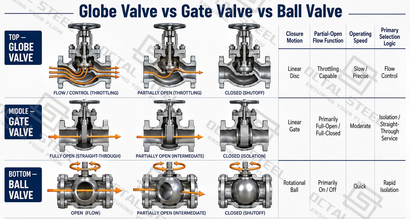
Globe Valve vs Gate Valve
The principal globe valve vs gate valve difference is the intended operating position. A globe valve can remain at intermediate disc positions to regulate flow. A gate valve is designed primarily to withdraw the gate from the passage for full flow or lower it into the seat for isolation. The result is better throttling capability from the globe valve but lower fully open flow resistance from the gate valve.
Globe Valve vs Ball Valve
In a globe valve vs ball valve comparison, the globe valve uses linear disc travel and an adjustable seat restriction, while a conventional ball valve obtains rapid shutoff through approximately quarter-turn ball rotation. A full-bore ball valve offers a much straighter open passage. Specialized V-port or characterized control-ball designs should be evaluated separately from conventional isolation ball valves.
Download:Industrial Globe Valve Technical Reference.pdf
Globe Valve Materials and Trim Selection
A globe valve experiences different loads and degradation mechanisms at different components. Body material controls the principal pressure boundary, while the disc-seat region receives concentrated hydraulic loading during throttling. Material selection therefore needs to be made as a system.
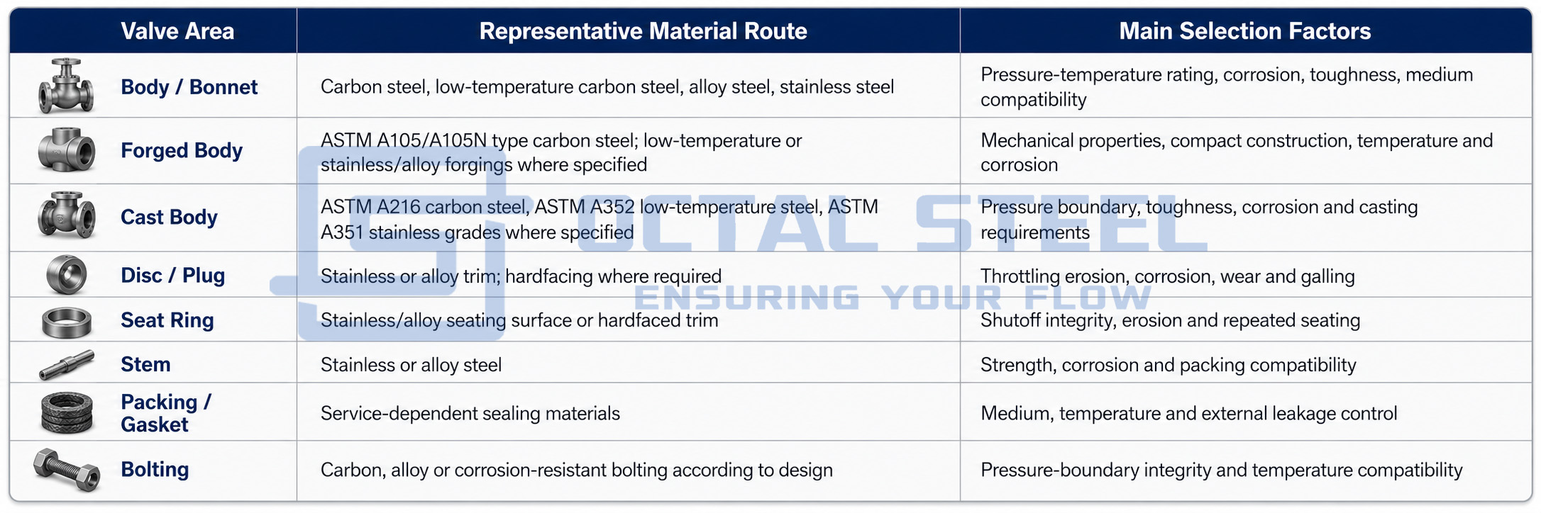
The current OCTAL STEEL valve portfolio already references carbon-steel, low-temperature, stainless-steel, alloy and special-alloy material families. For a dedicated Globe Valve order, however, the exact material combination should be tied to the selected design, class, temperature and trim requirement rather than assuming every listed alloy applies across the full size range.
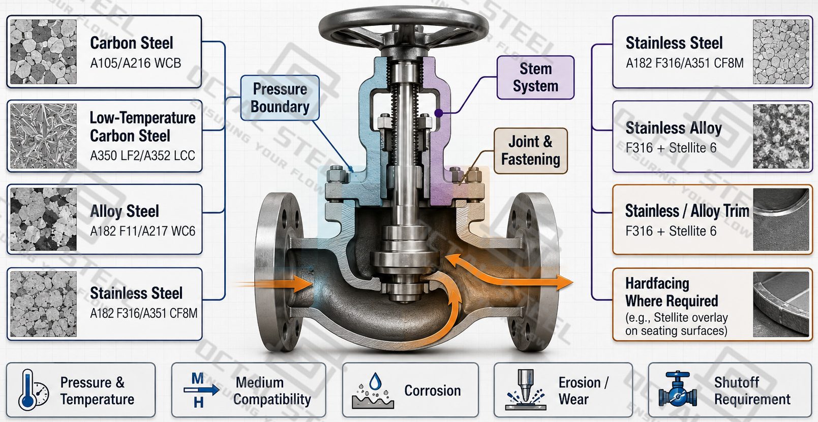
A stainless steel globe valve becomes relevant when the body and wetted components require greater corrosion resistance than a carbon-steel configuration can provide. Trim selection still needs separate attention because stainless body material by itself does not define resistance to throttling erosion or seat galling.
API 623 Globe Valve and Applicable Standards
Industrial Globe Valve specifications normally combine a valve product standard with pressure-boundary, dimensional, end-preparation and testing requirements.
| Standard | Main Control |
|---|---|
| API 623 | Heavy-duty bolted-bonnet steel globe valves with flanged and butt-welding ends |
| API 602 | Compact gate, globe and check valves through DN100 / NPS 4 |
| ASME B16.34 | Pressure-temperature ratings, materials, dimensions/tolerances, NDE, testing and marking for applicable valve construction |
| ASME B16.10 | Face-to-face/end-to-end dimensions and center-to-face dimensions for angle valves |
| ASME B16.25 | Preparation of butt-welding ends |
| API 598 | Valve inspection, examination and pressure testing |
API describes API 623 globe valve construction as a heavy-duty series of bolted-bonnet steel globe valves for petroleum refinery and related applications. API 602 covers compact valves through NPS 4, while ASME B16.34 establishes the broader pressure-temperature, material, NDE, testing and marking framework for covered valve construction.
ASME B16.10 controls installation dimensions, including center-to-face/end dimensions relevant to angle valves, while ASME B16.25 controls butt-welding end preparation.
The applicable combination must be confirmed on the purchase specification. A size or Class appearing in a supply table does not by itself establish compliance with a particular valve standard.
Industrial Globe Valve Selection Criteria
A useful project selection sequence starts with the process requirement and ends with inspection and documentation.
1. Define the operating duty.
Confirm whether the valve will perform continuous throttling, occasional adjustment, controlled start-up, pressure reduction, shutoff, or a combination of these functions. Frequent throttling places greater importance on trim geometry and wear resistance.
2. Define the process medium.
Identify corrosion potential, solids content, viscosity and compatibility with the body, seat, disc, stem and sealing materials. Slurries or heavily contaminated media need additional review because the restricted globe-valve passage can experience blockage and accelerated erosion.
3. Establish pressure and temperature.
These inputs determine the required pressure class and influence body/bonnet material, packing, gasket, bolting and bonnet construction.
4. Check allowable system pressure drop.
A conventional T-pattern creates more resistance than a Y-pattern or a straight-through isolation valve. Hydraulic requirements therefore influence body-pattern selection.
5. Select the applicable standard and construction.
Determine whether the requirement falls under an API 623 bolted-bonnet design, API 602 compact construction, EN bellows-seal route, pressure-seal configuration or another approved project standard.
6. Complete the mechanical specification.
Confirm body pattern, body and trim materials, bonnet arrangement, flow direction, end connection and manual or actuated operation.
7. Define release requirements.
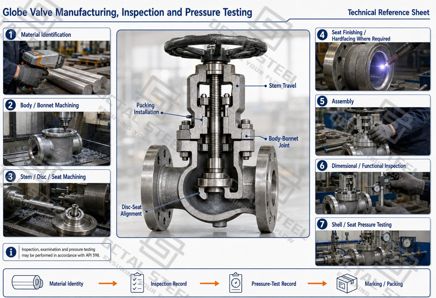
The purchase specification should state material traceability, dimensional and functional inspection, pressure testing and required documentation before shipment.
Manufacturing, Inspection and Pressure Testing
Industrial Globe Valve Applications
Industrial globe valves are most useful where a process line needs controlled adjustment in addition to shutoff. Their value comes from the progressive change in disc-seat opening, so the operating condition matters more than the industry name alone.
Refinery and Process Flow Regulation
Process lines may require an operator or actuator to adjust flow repeatedly as operating conditions change. A globe valve provides predictable intermediate positions through linear stem travel, while the body and trim are selected for the medium, temperature and expected throttling duty.
Steam, Condensate and Utility Service
Steam and utility systems often require gradual introduction or reduction of flow during start-up, normal operation and shutdown. Higher-temperature conditions place additional emphasis on bonnet construction, packing, gasket, bolting and trim compatibility.
Chemical and Corrosive Process Lines
Carbon steel, alloy or stainless steel globe valve construction can be selected according to medium compatibility. The disc and seat require separate consideration because throttling exposes the trim to concentrated velocity, turbulence, corrosion and possible erosion.
Bypass and Start-Up Lines
A globe valve can gradually establish flow through a bypass during filling, warming, pressure equalization or equipment start-up. Actual valve size and trim should be checked against differential pressure and operating duty rather than selected only from line size.
Piping Requiring Regulation and Direction Change
An angle globe valve is useful when a piping layout requires a direction change at the same location as throttling or shutoff. The 90-degree body arrangement combines these functions while reducing the need for a separate elbow.
Download:Industrial Globe Valve Selection Technical Reference.pdf
OCTAL STEEL Globe Valve Supply and Project Support
OCTAL STEEL supplies industrial globe valve configurations covering cast steel, forged steel and pressure-seal constructions, with carbon steel, alloy steel and stainless steel material routes for refinery, chemical, power and related process piping requirements.
Project support can be developed around valve size and pressure class, applicable design standard, body pattern, body and trim materials, bonnet construction, flanged or butt-welded ends, manual or actuated operation, inspection requirements and documentation. Special configurations such as bellows-seal globe valves can be evaluated separately where the service requires an additional stem containment barrier.
Final release should match the confirmed product specification rather than applying the maximum catalog size, pressure class or material range to every configuration.
FAQ
Does a Class 2500 forged globe valve automatically comply with API 602?
No. API 602 covers compact globe valves through NPS 4 but its published pressure-class scope includes Classes 150, 300, 600, 800 and 1500. A Class 2500 forged globe valve requires confirmation of another applicable design basis or project specification.
When should a bellows seal globe valve be specified?
Bellows-seal construction is considered when the process requires additional control of leakage around the stem. The bellows material, design cycles, pressure-temperature condition and applicable standard should be confirmed for the actual medium and operating duty.
Why does flow direction matter on a globe valve?
Differential pressure acts on the disc and changes the hydraulic force that the stem and operator must overcome. The specified installation direction should therefore follow the approved valve design and manufacturer flow marking.
What information is needed for a globe valve quotation?
Provide the medium, design pressure and temperature, valve size and class, required standard, body pattern, body and trim materials, bonnet type, end connection, operating method, flow direction, inspection requirements and documentation requirements.