Your Responsible Supplier Partner for Oil and Gas Products.

Gate Valve
Recent Products

Rencent Articles





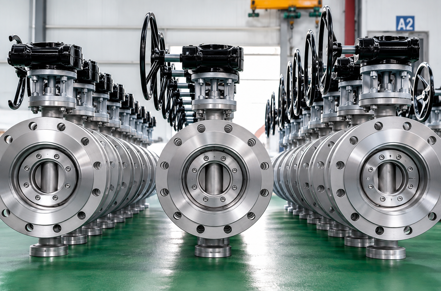
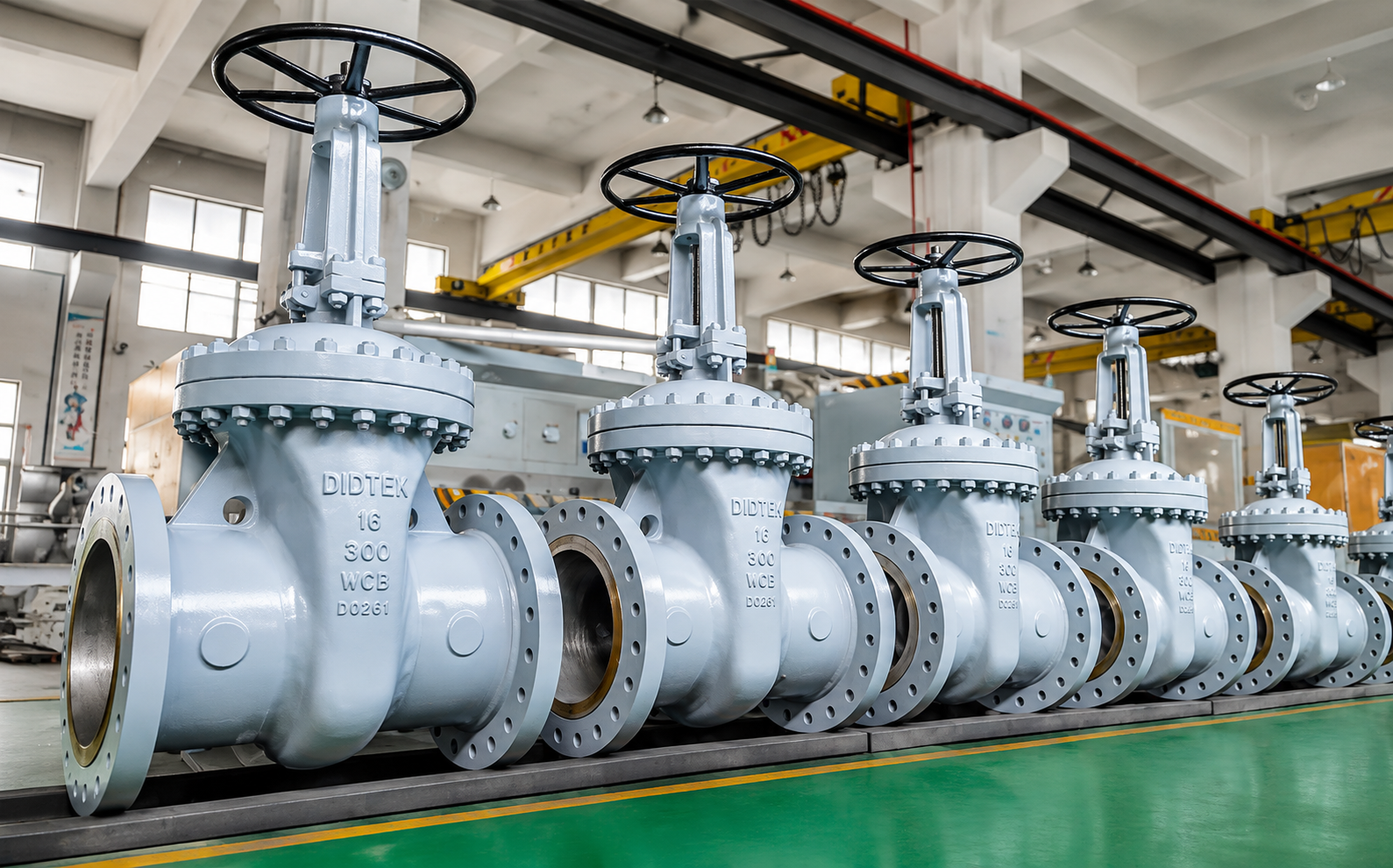
Gate Valve
Gate Designs: Wedge, slab and through-conduit configurations
Body Construction: Cast or forged steel
Stem Design: Rising and non-rising stem
Bonnet Options: Bolted bonnet and pressure-seal bonnet
End Connections: Flanged or butt-welded
Operation: Handwheel, gearbox or actuator for industrial isolation service
A gate valve is a multi-turn industrial isolation valve built from a cast or forged pressure-containing body, gate or wedge, stem, seats, bonnet and stem-sealing system. Rotation from a handwheel, gearbox or actuator is converted through the threaded stem into linear gate movement: the gate rises out of the flow path to open the line and travels back between the seats to shut it off. Because the closure element moves largely clear of the main passage when fully open, a correctly selected gate valve provides a relatively unrestricted flow path and low pressure loss compared with valves that leave a closure element in the flowing stream.
Industrial steel gate valves are selected according to pressure class, gate design, body construction, stem and bonnet arrangement, seating system, materials, end connection, operating temperature, fluid medium and actuation method. Wedge, slab, cast steel and forged steel gate valve configurations are matched to the required pipeline or process conditions so that pressure containment, shutoff sealing, operating force and service life remain suitable for the specified duty.
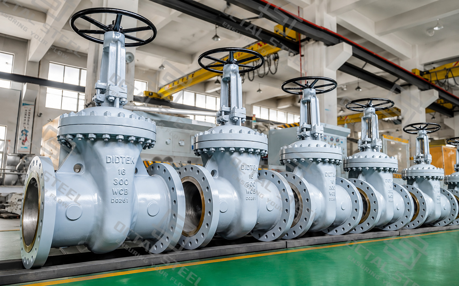
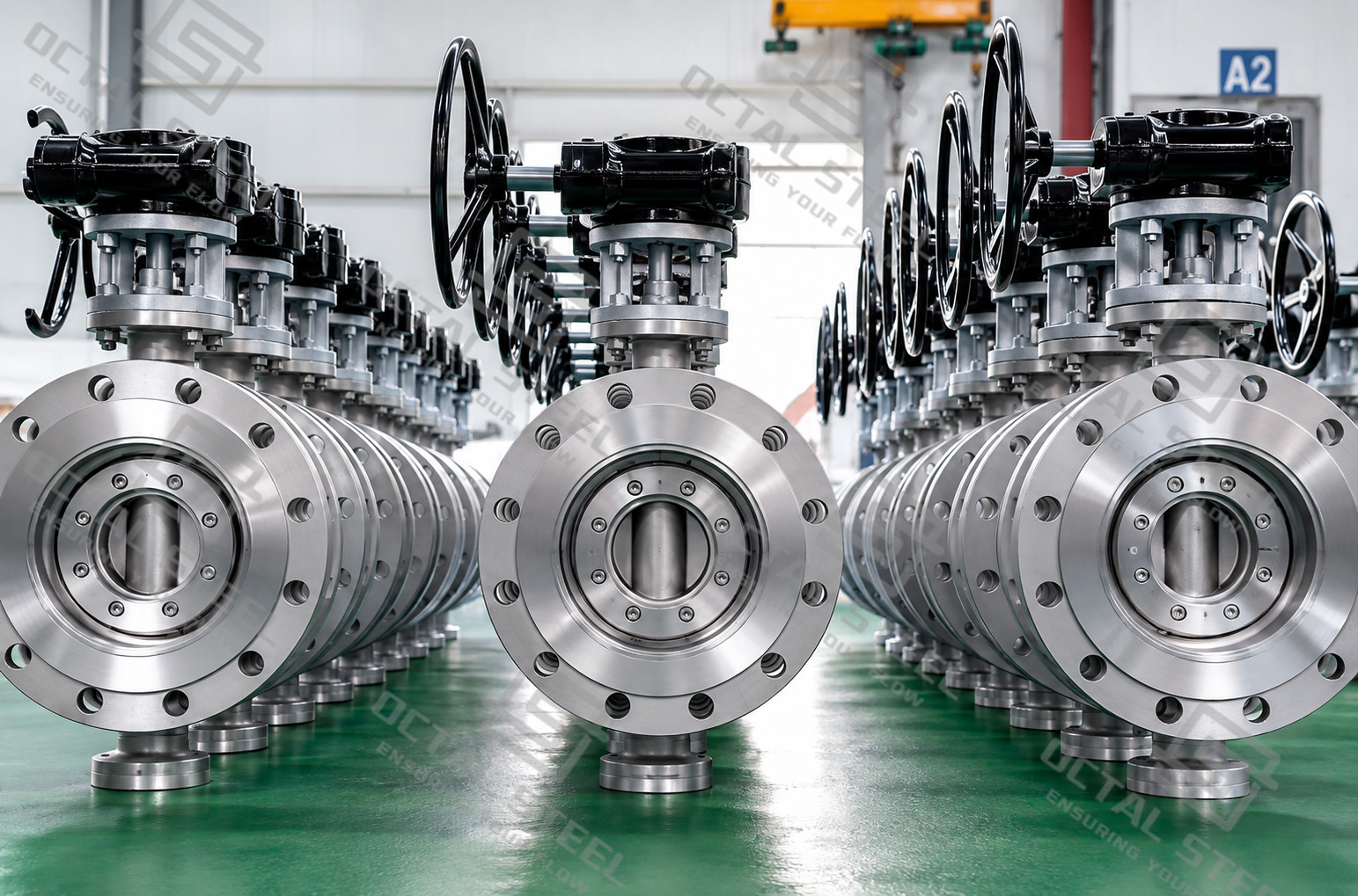
Gate Valve Specifications and Engineering Configurations
Industrial gate valves can be classified in several different ways. These classifications should not be mixed into one generic “types” list because each describes a different part of the valve design.
| Classification Basis | Main Options | What It Changes |
|---|---|---|
| Gate Design | Wedge, slab, expanding gate | Sealing mechanism, body cavity and suitability for pipeline service |
| Body Manufacturing | Cast steel, forged steel | Available geometry, size range and manufacturing route |
| Stem Design | Rising stem, non-rising stem | Position indication, installation height and stem/thread arrangement |
| Bonnet | Bolted bonnet, pressure-seal bonnet | Body-bonnet sealing and suitability for pressure/temperature service |
| End Connection | Flanged, butt-welded; threaded/socket-welded on applicable compact valves | Pipeline connection and maintenance/installation method |
| Material System | Carbon, low-temperature, alloy or stainless steel with specified trim | Pressure-temperature capability and media compatibility |
| Operation | Handwheel, gearbox or actuator | Operating force, automation and remote-control requirements |
Their representative size and class envelopes differ, which is why an actual size × Class × material × end-connection combination should always be confirmed rather than inferred from the maximum family range.
How a Gate Valve Works
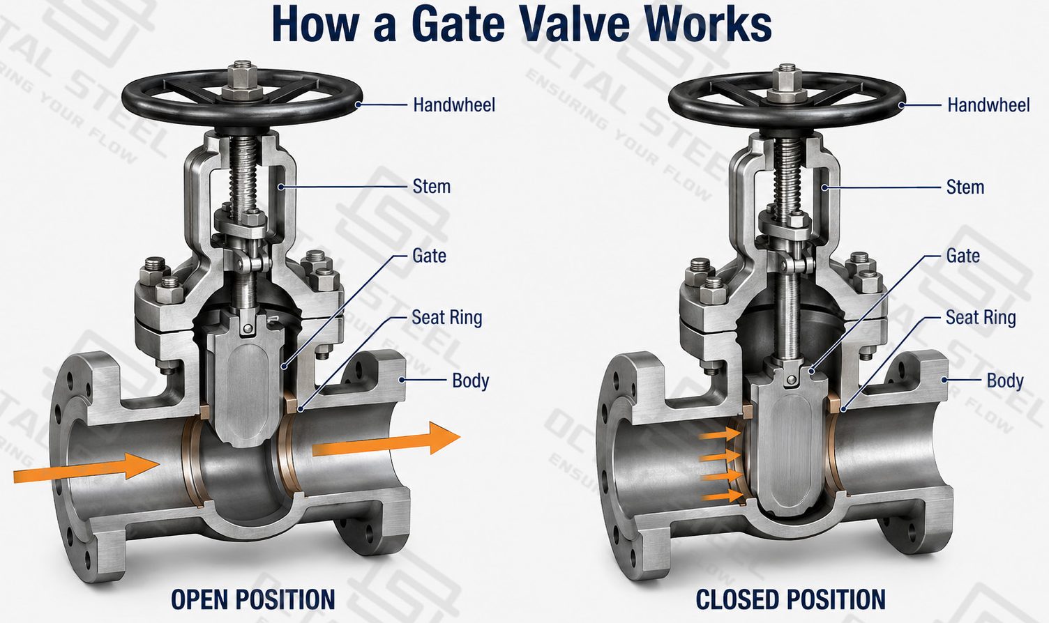
Gate Valve Parts and Functions
The operating mechanism is only one part of the design. Each major component controls a different engineering requirement.
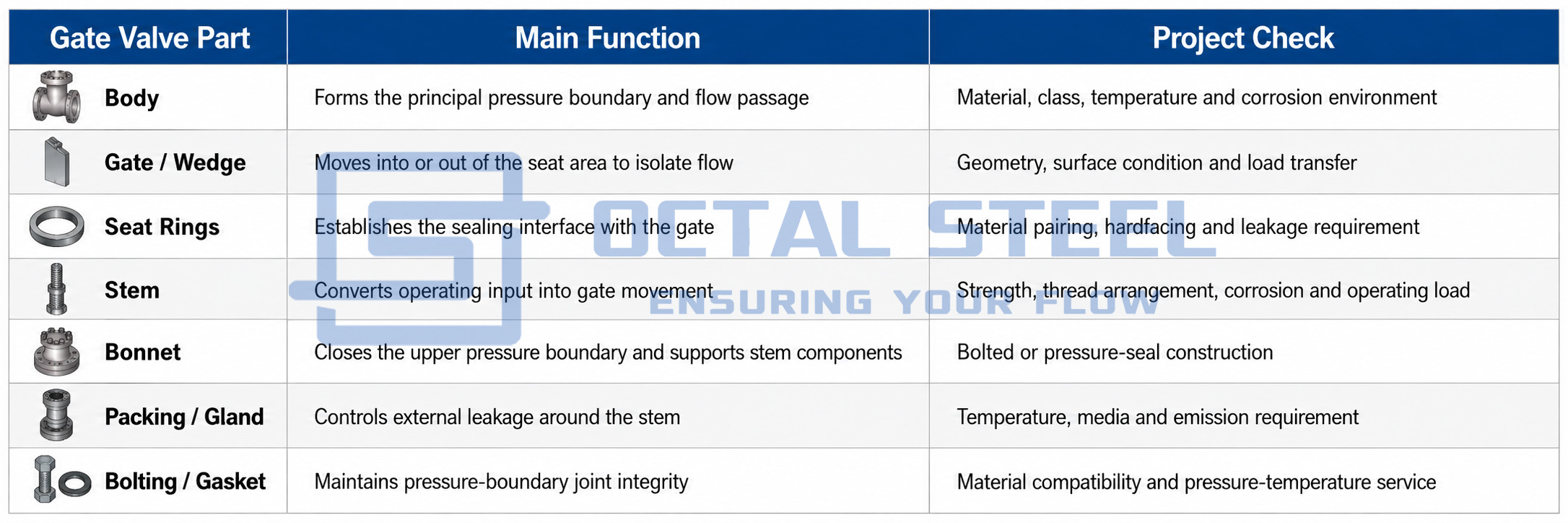
This component-by-component approach is especially important for an industrial gate valve because specifying only “carbon steel gate valve” does not define the trim, seat facing, stem, packing or bonnet joint that actually determine whether the valve suits the service.
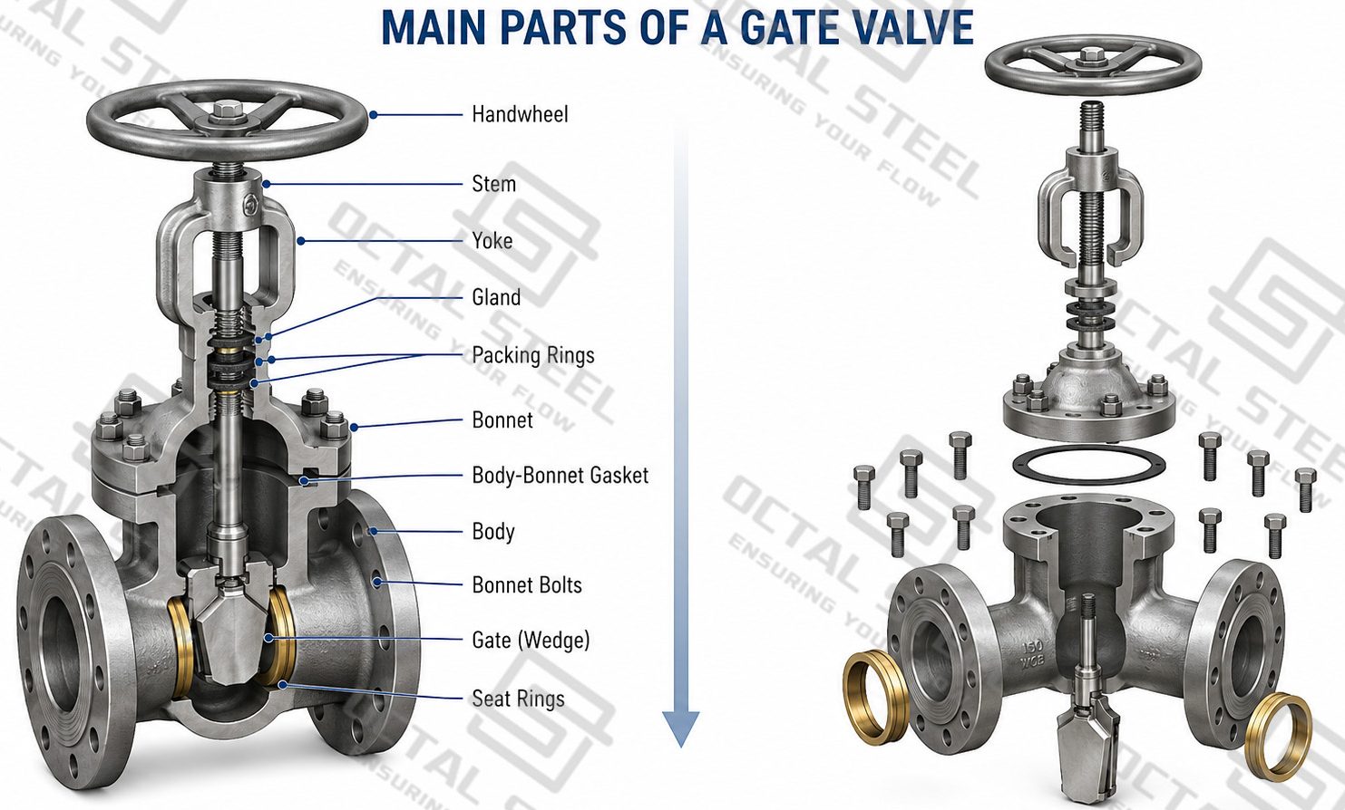
Gate Valve Types by Engineering Design
Wedge Gate Valve
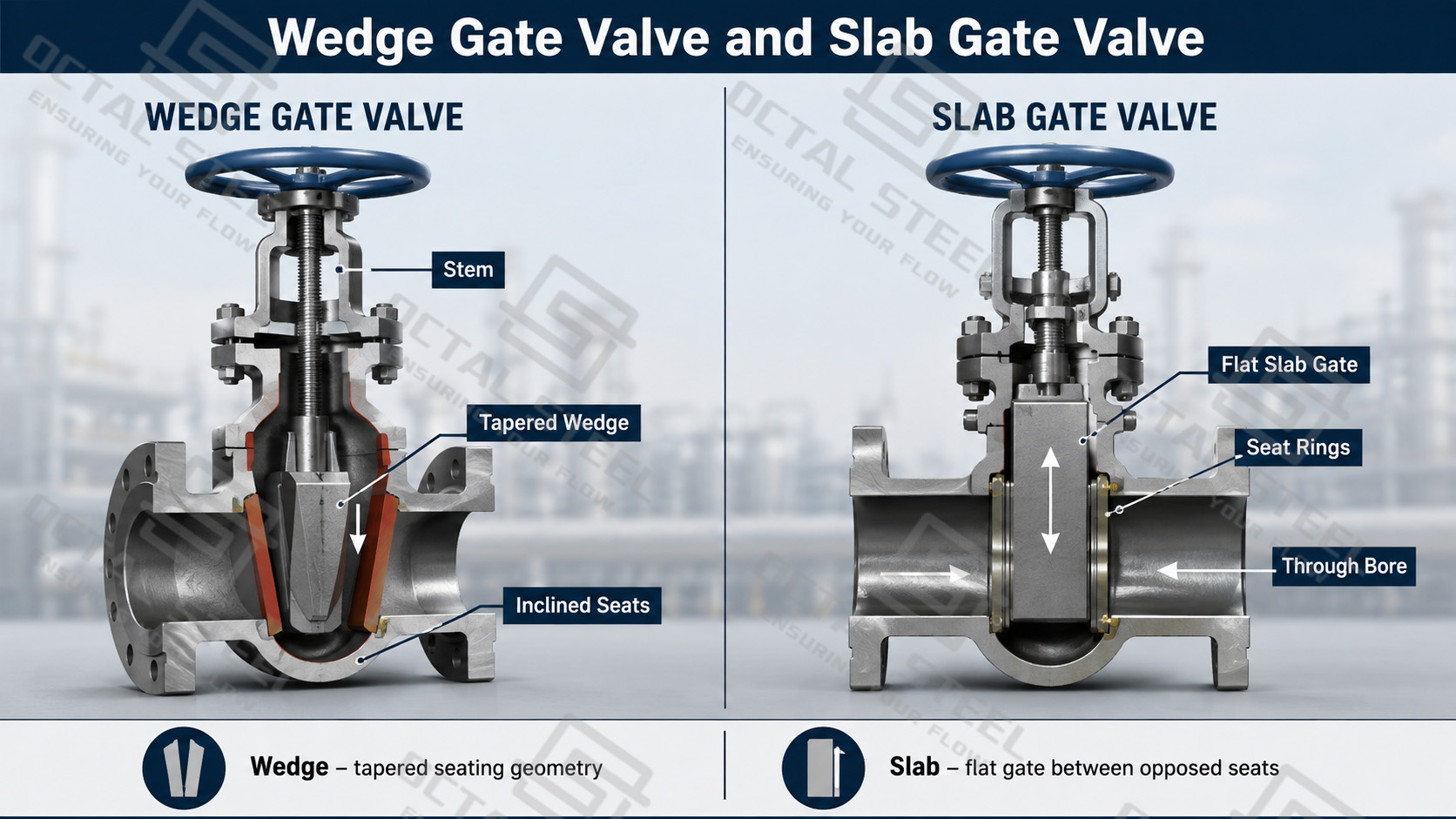
A wedge gate valve uses a tapered closure element that moves between inclined seating surfaces. The wedge geometry allows seating load to develop as the valve reaches the closed position. Industrial designs may use solid or flexible wedge arrangements depending on design and service requirements.
A flexible wedge can accommodate limited changes in seating alignment caused by temperature or structural distortion while preserving contact between the wedge and seat surfaces. The supplied cast-steel valve reference also identifies machined/lapped seating surfaces and hardfaced or corrosion-resistant seat options as important parts of the sealing system.
Wedge gate valves are well suited to process and plant isolation, but they should not automatically be described as piggable. SLB distinguishes wedge designs from through-conduit slab or expanding gate designs because the internal body geometry and gate arrangement are different.
Slab Gate Valve
A slab gate valve uses a single flat gate moving between two seat rings. Through-conduit versions can maintain a continuous bore when fully open, making this construction particularly relevant to pipeline isolation where bore continuity and pig passage are project requirements. Actual piggability still needs confirmation against both the valve bore and connected pipeline geometry.
The supplied technical data also identifies slab gate valves as a separate steel-valve family rather than a variation of an API 600 wedge valve, reinforcing the need to select them according to pipeline function rather than only nominal size.
Cast Steel Gate Valve
A cast steel gate valve uses a cast pressure-containing body, allowing relatively complex body geometry and broad industrial valve configurations. API 600 is a key product standard for bolted-bonnet steel gate valves with flanged or butt-welding ends.
Carbon steel, low-temperature steel, alloy steel or stainless material routes may be considered depending on the applicable product standard and service requirements. Body material selection must be coordinated with the stem, wedge, seats, packing, bolting and required pressure-temperature rating rather than treated as an isolated specification.
Forged Steel Gate Valve
A forged steel gate valve is commonly used where a compact steel valve configuration is required, particularly in smaller nominal sizes and demanding pressure service. API 602 specifically covers Gate, Globe and Check valves at DN 100 / NPS 4 and smaller for petroleum and natural-gas industries.
The supplied product material also shows forged gate valves with flanged, butt-welded, threaded and socket-welded connection routes depending on configuration. These options should be treated as family capabilities, not as proof that every end connection is available for every pressure class.
Gate Valve Stem and Bonnet Design
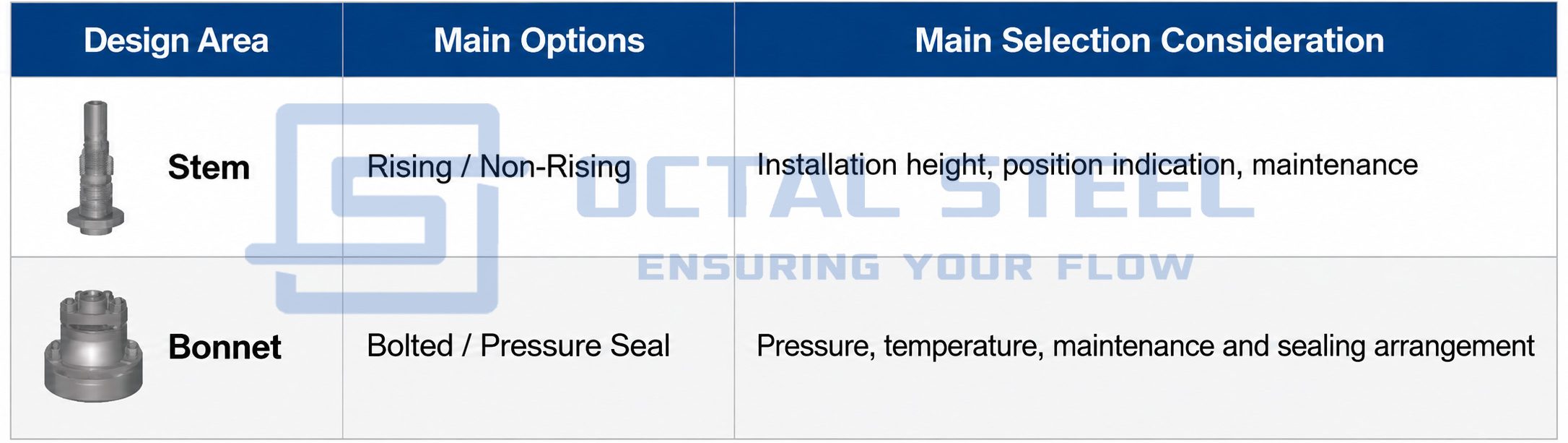
Stem design controls how gate movement is transmitted and how much installation space the valve requires. A rising-stem gate valve moves the stem upward together with the gate, providing visible position indication but requiring additional vertical clearance. A non-rising stem keeps the operating height more compact while the gate travels along the threaded stem, making it useful where installation space is limited.
Bonnet construction forms the upper pressure boundary of the valve. Bolted-bonnet designs use a bolted body-to-bonnet joint and are common on industrial steel gate valves. Pressure-seal bonnets use line pressure to reinforce the bonnet sealing arrangement and are considered for higher-pressure and higher-temperature service.
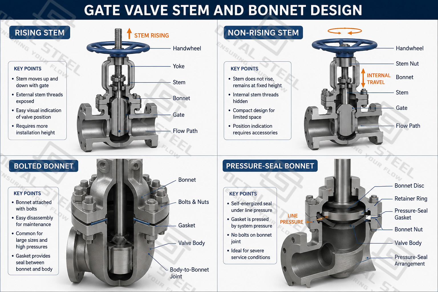
Download:Gate Valve Design Structure and Operating Mechanism Guide.pdf
API 600 Gate Valve and Applicable Standards
For an industrial steel gate valve, the standard package controls different parts of the product rather than functioning as one generic certification.
| Standard | Main Relevance |
|---|---|
| API 600 | Steel gate valves with flanged or butt-welding ends and bolted bonnets |
| API 602 | Compact Gate, Globe and Check valves DN 100 / NPS 4 and smaller for petroleum and natural-gas service |
| API 603 | Corrosion-resistant bolted-bonnet gate valves |
| API 6D | Pipeline and piping valves, including applicable gate-valve configurations |
| API 598 | Valve inspection and testing |
| ASME B16.34 | Pressure-temperature ratings, materials, dimensions, NDE, testing and marking for applicable valves |
| ASME B16.10 | Face-to-face and end-to-end dimensions |
API currently identifies these Gate Valve standards separately, while ASME B16.34 covers pressure-temperature ratings and other construction requirements for cast, forged and fabricated flanged, threaded and welding-end valves. ASME B16.10 controls dimensional interchangeability by valve type, size, rating class and end connection.
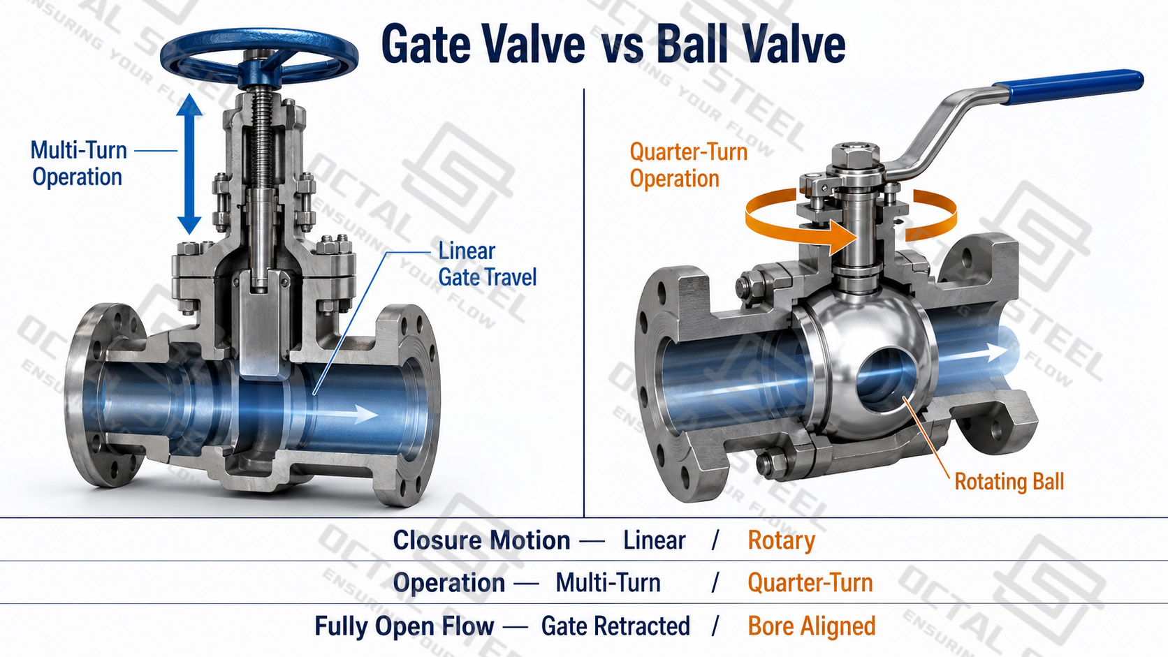
Gate Valve vs Ball Valve
Gate valves and ball valves are both used for pipeline isolation, but they achieve shutoff through different closure mechanisms. A gate valve moves a gate linearly into or out of the flow passage, while a ball valve rotates a bored ball through 90°. These structural differences affect operating speed, flow path, actuation and the conditions for which each valve is better suited.
| Selection Point | Gate Valve | Ball Valve |
|---|---|---|
| Closure Movement | Linear gate travel | 90° ball rotation |
| Operation | Multi-turn | Quarter-turn |
| Fully Open Flow Path | Gate retracts from the main flow passage | Ball bore aligns with the pipeline |
| Operating Speed | Slower because several stem turns are required | Faster quarter-turn operation |
| Primary Duty | Full-open or full-closed isolation | Isolation and rapid shutoff |
| Flow Restriction | Low when the gate is fully retracted | Low with a correctly sized full-bore design |
| Pigging Capability | Depends on gate and body construction; through-conduit designs may be suitable | Depends on actual valve bore and pipeline bore |
| Main Selection Factors | Gate design, stem, bonnet, seats and service conditions | Ball support, bore, seat system, torque and service conditions |
A gate valve is generally preferred where the valve remains fully open for long periods and a clear flow passage with low restriction is important. A ball valve is often selected where fast shutoff, frequent operation or automated quarter-turn control is required. For either design, final selection should consider pressure differential, temperature, medium, operating frequency, sealing requirement, bore configuration and actuator requirements rather than nominal size alone.
Gate Valve Materials and Trim Selection
The pressure-containing body is only the first material decision. A complete material schedule should address:
- body and bonnet material;
- gate or wedge material;
- stem grade;
- seat rings and seat-facing material;
- packing and gasket system;
- bolting;
- any hardfacing or corrosion-resistant overlay required by the service.
Carbon steel is commonly considered for general hydrocarbon and process service, while low-temperature, alloy and stainless steel routes may be required as temperature or corrosion conditions change. Seat and stem materials must then be matched to the body, fluid and operating conditions rather than selected independently.
For high-temperature, corrosive or erosive service, the sealing surfaces deserve particular attention because an acceptable body material does not guarantee suitable trim performance.
How to Select a Gate Valve for a Project
Gate valve selection should begin with the actual operating conditions of the line. The main checks are:
- Line service and medium: Confirm whether the valve is used for pipeline isolation, process shutoff or high-temperature service, together with the fluid composition and presence of solids or corrosive components.
- Size and pressure class: Match the nominal size and pressure class to the piping system and applicable design standard, such as API 600, API 602 or API 6D where relevant.
- Gate and body design: Select a wedge, slab or other applicable gate design, then determine cast or forged body construction according to size, pressure and service requirements.
- Materials and sealing surfaces: Specify the body, gate, stem, seat/trim, packing and bolting materials according to operating temperature, corrosion conditions and required shutoff performance.
- Connection and operation: Confirm flanged or butt-welded ends, stem/bonnet configuration, and whether handwheel, gearbox or actuator operation is required.
Before release, the valve specification should also define inspection, pressure testing, material certificates and required project documentation. This prevents a valve from matching only the size and Class while the gate design, trim or operating arrangement remains unsuitable for the actual service.
Manufacturing and Quality Control
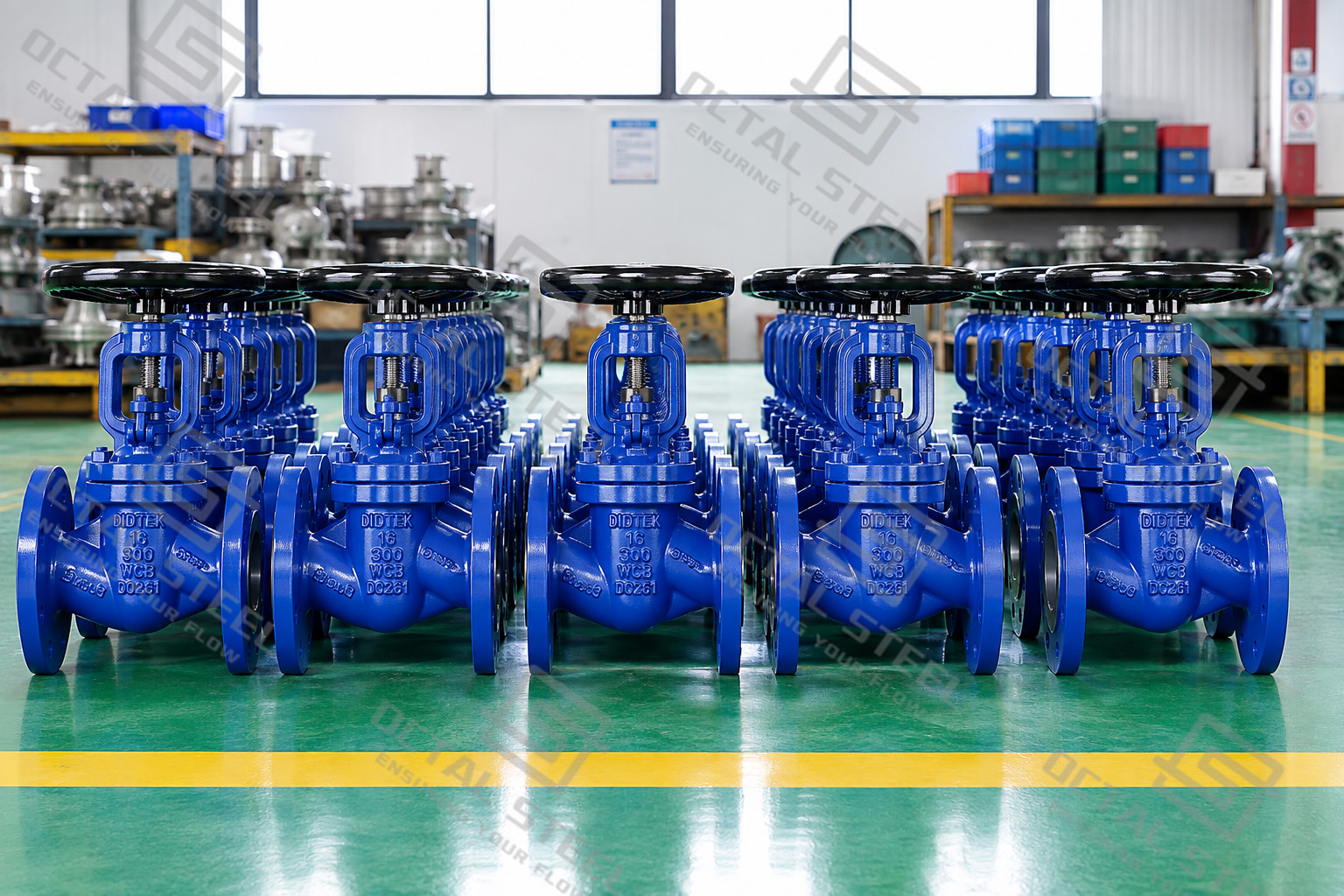
Manufacturing quality is controlled at several points rather than only by the final pressure test.
Typical controls include material identification and traceability, casting or forging condition, pressure-boundary machining, stem and thread dimensions, wedge and seat surface preparation, body-to-bonnet fit-up, packing assembly, functional operation, shell and seat pressure testing, marking and release documentation.
For applicable steel valves, ASME B16.34 includes requirements covering materials, dimensions, nondestructive examination, testing and marking, while API 598 is specifically used for valve inspection and testing. Exact test pressures, acceptance criteria and NDE coverage should follow the specified standard and project ITP rather than being applied as one universal number to every Gate Valve configuration.
Download:Gate Valve Standards Materials Selection and Project Release Guide.pdf
Industrial Gate Valve Applications
Pipeline block isolation: Through-conduit or slab gate configurations can be considered where the line needs a low-restriction open passage and, where required, verified pigging continuity.
Refinery and process piping: Cast or forged steel gate valves provide on-off isolation on process lines that normally remain fully open or fully closed for extended operating periods.
High-pressure and high-temperature systems: Alloy materials and pressure-seal bonnet configurations can be evaluated where operating pressure and temperature exceed the practical range of conventional configurations.
Plant maintenance isolation: Flanged or butt-welded gate valves can isolate process equipment or sections of piping during shutdown, inspection and equipment replacement.
The application should always be tied back to pressure, temperature, media, cycling frequency and sealing requirement rather than selected only by industry name.
FAQ
Q: What is an API 600 gate valve?
A: API 600 covers bolted-bonnet steel gate valves with flanged or butt-welding ends and defines requirements for industrial steel valve construction.
Q: Can a gate valve be used for throttling?
A: Conventional gate valves are intended mainly for fully open or fully closed isolation. Partial opening can expose the gate and seats to unstable high-velocity flow, vibration and erosion.
Q: What is the difference between a wedge gate valve and a slab gate valve?
A: A wedge valve closes a tapered gate against inclined seating surfaces, while a slab valve moves a flat gate between seat rings. Through-conduit slab designs may be selected where pipeline bore continuity is important.
Q: What information is needed to specify an industrial gate valve?
A: Specify size, pressure class, design standard, body and trim materials, gate type, stem and bonnet construction, end connection, temperature, medium, actuation and required inspection/documentation.