Your Responsible Supplier Partner for Oil and Gas Products.

Spiral Silo
Recent Products


Rencent Articles

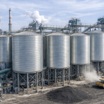
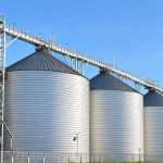



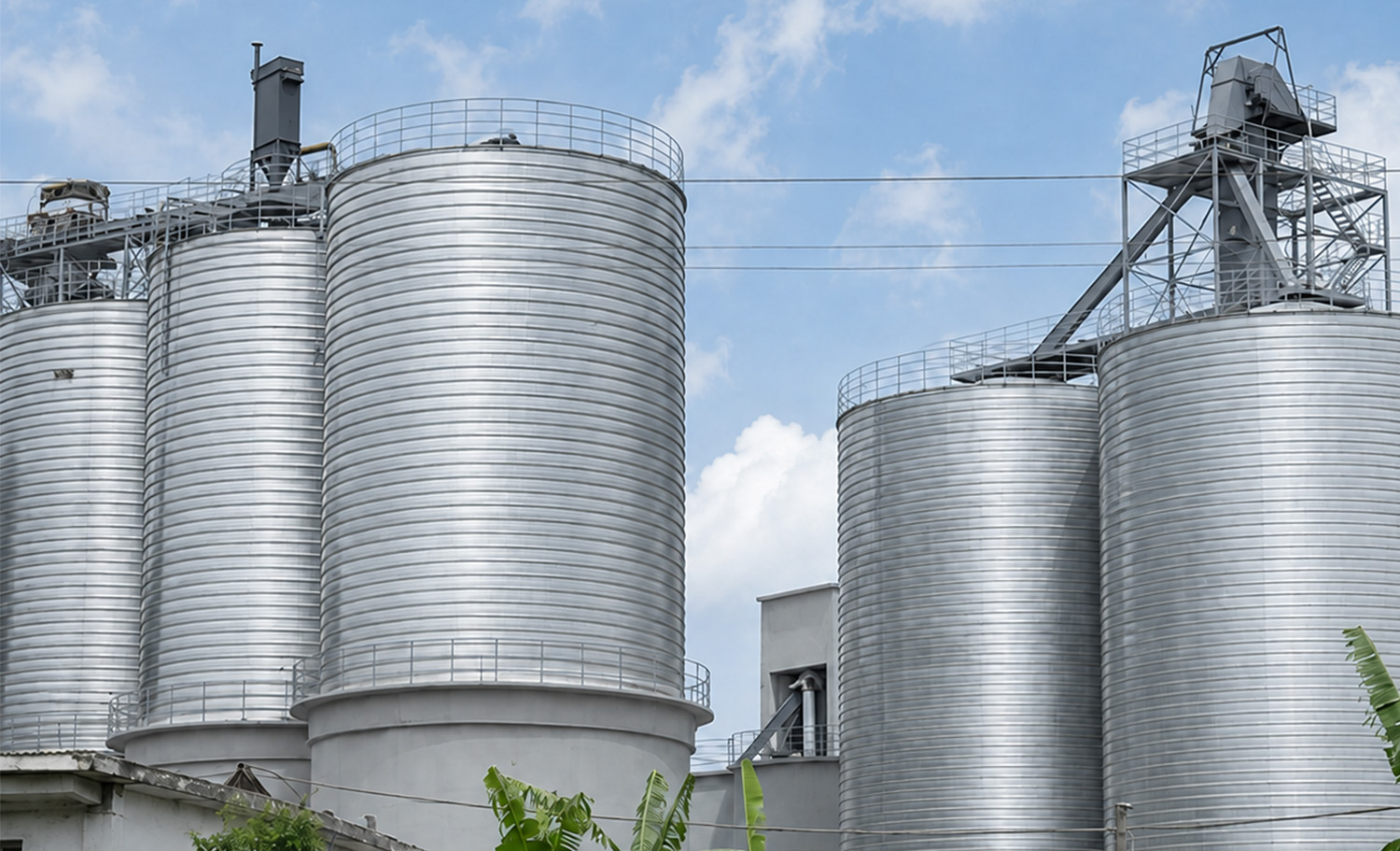
Spiral Silo
Construction Types: Double-folded spiral seam and automated welded spiral seam for continuous on-site shell forming.
Storage Function: Enclosed storage protects suitable dry bulk materials from moisture ingress, contamination and material loss.
System Integration: Compatible with pneumatic or mechanical filling, vent filtration, pressure relief, level monitoring, aeration and controlled discharge.
Applications: Cement, fly ash, mineral powder, dry mortar materials, grain, feed ingredients and bulk receiving terminals.
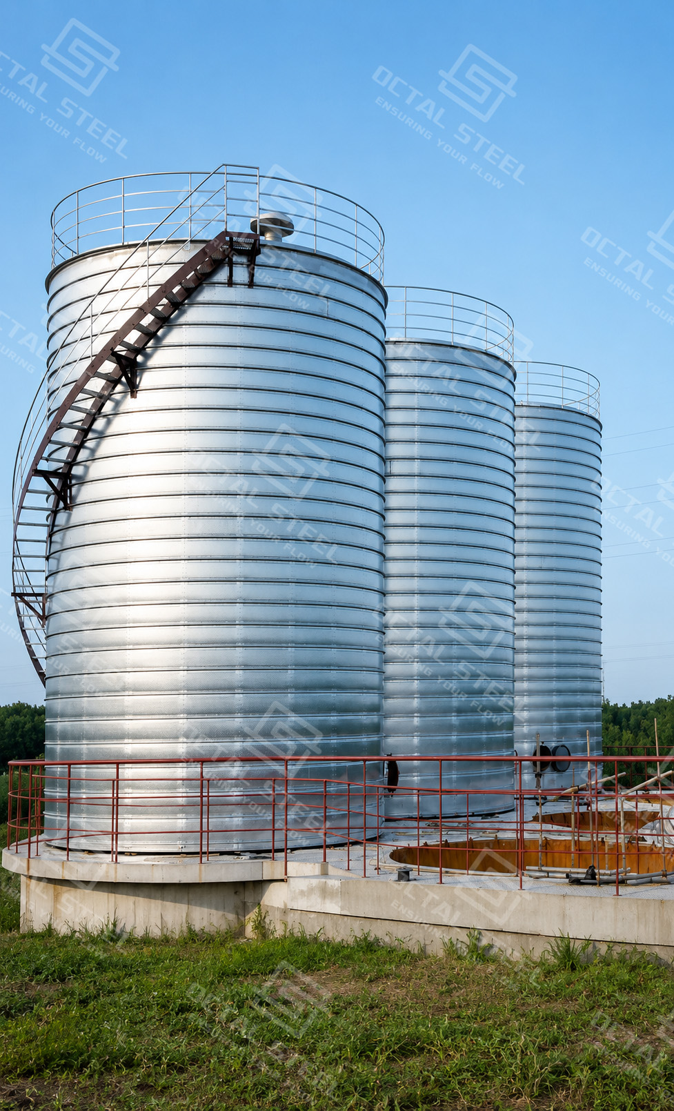
Spiral silo is a cylindrical bulk-storage structure whose steel shell is continuously formed at the installation site rather than assembled from separate wall panels. The shell is commonly produced from galvanized steel coil, while carbon steel, stainless steel or a project-specific protective system may be used where the stored material, humidity or corrosion environment requires it. During construction, the steel strip is unwound, guided through profiling rollers and curved to the specified silo diameter. Each new strip edge is then mechanically folded together with the preceding strip to create a continuous double-folded spiral seam, producing an integral wall with no conventional horizontal bolted panel joints.
The completed spiral steel silo can be configured for cement, fly ash, mineral powder, grain and other suitable dry bulk materials. The actual storage arrangement is determined by material bulk density, particle size, moisture, flowability, abrasiveness, storage period and required discharge rate. Powder applications typically require pneumatic filling, vent filtration, pressure protection and aerated discharge, while grain storage may require mechanical conveying, aeration and temperature monitoring. Octal Steel coordinates the silo shell, roof, bottom structure, filling system, discharge equipment and monitoring interfaces around the actual material-handling duty.
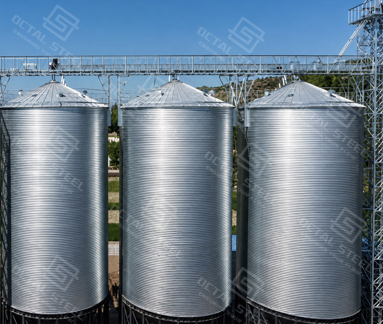
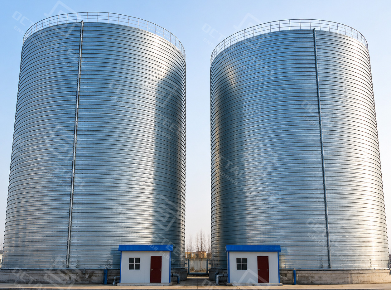
Spiral Silo Configurations
Spiral silo configuration is defined by the storage duty rather than by a universal model series. Diameter, wall height, shell material, bottom arrangement and auxiliary equipment are selected according to the stored material, required inventory, filling method, discharge rate and site conditions. The principal configurations can therefore be grouped by bottom structure and process application.
| Configuration | Typical Operating Duty | Common System Features | Main Design Consideration |
|---|---|---|---|
| Flat-Bottom Spiral Silo | Large-volume or long-term storage | Reclaim conveyor, multiple outlets, sweep system or fluidized discharge | Residual material and reclaim coverage |
| Hopper-Bottom Spiral Silo | Frequent filling and discharge | Gravity outlet, flow-control gate, screw conveyor or air slide | Material flowability and hopper support |
| Industrial Powder Silo | Cement, fly ash, slag powder, lime powder and other suitable powders | Pneumatic filling, top filter, pressure protection and flow assistance | Dust loading, caking and aeration behavior |
| Grain Storage Silo | Wheat, corn, rice and feed ingredients | Bucket elevator, aeration, temperature monitoring and reclaim equipment | Moisture, biological activity and combustible dust |
| Process Buffer Silo | Intermediate storage between production stages | Controlled filling, metered discharge and level-based automation | Stable flow to downstream equipment |
| Bulk Terminal Silo | Receiving, intermediate storage and truck or process loading | High-rate conveying, multiple transfer points and centralized controls | Peak filling and discharge rates |
The bottom arrangement directly affects usable storage volume, discharge behavior, structural loading and reclaim equipment. Flat-bottom configurations are generally associated with larger inventories and require a defined reclaim system, while hopper-bottom configurations support more direct discharge where the material can flow reliably. Final selection must be based on bulk density, flowability, consolidation tendency, required discharge rate and operating cycle.
Continuous Spiral Forming and Main Structure
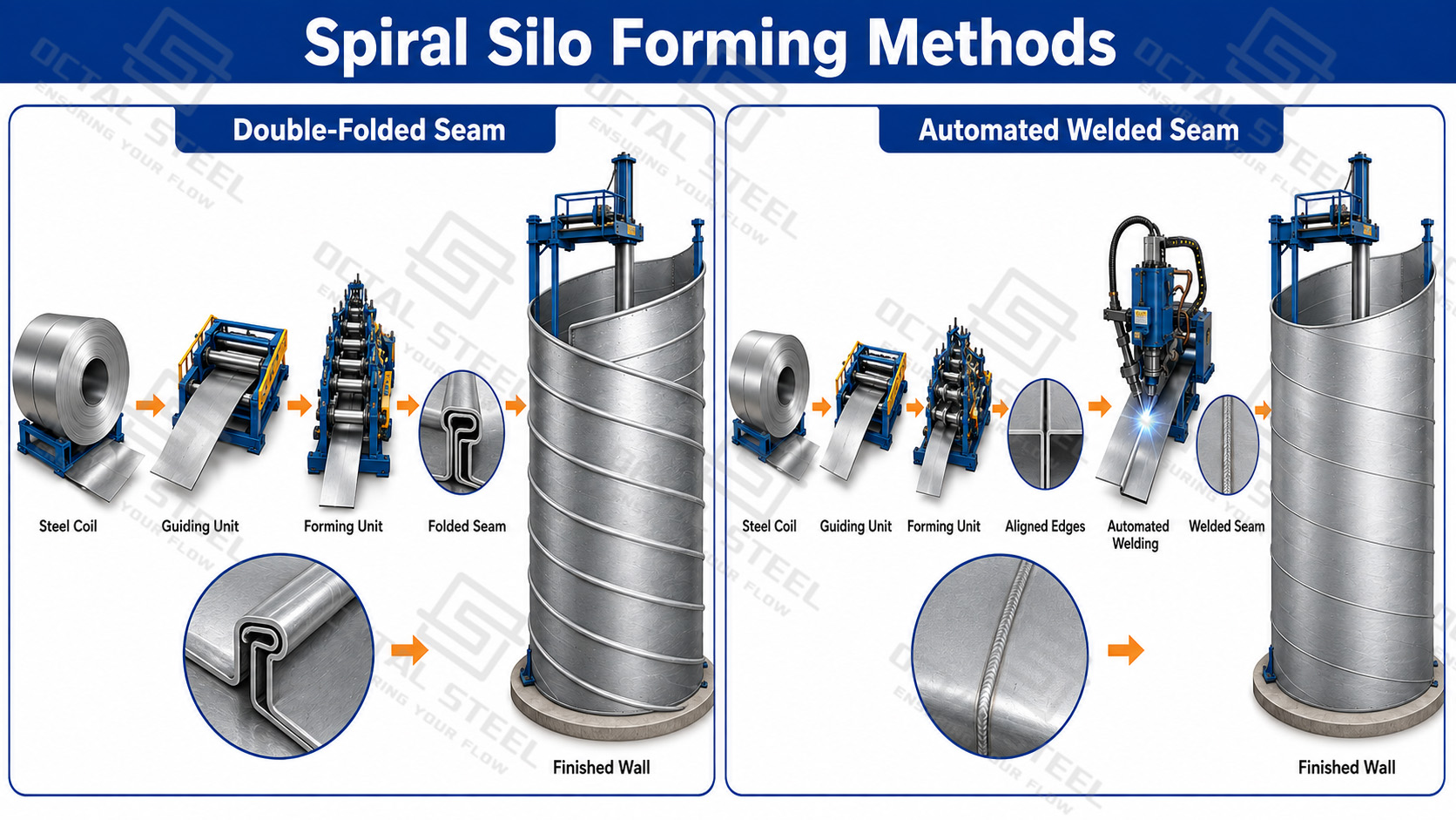
On-site spiral silo construction generally uses two shell-joining methods: a double-folded spiral seam or an automated welded spiral seam. Both methods continuously form steel coil to the specified silo diameter, but they differ in how adjacent strip edges are connected and in the materials and storage duties they can accommodate.
In the double-folded method, the steel strip is unwound, profiled and curved before its edge is aligned with the previously formed wall section. The two adjoining edges are then folded together twice by forming equipment, creating a mechanically interlocked spiral seam and a continuous cylindrical wall. This process is commonly applied to galvanized steel, black steel and stainless-steel systems where a smooth internal surface and controlled seam sealing are required.
In the welded method, the steel strip is similarly preformed to the required curvature, but adjacent edges are joined by an automated welding process rather than mechanical folding. The connection can be welded from the inside and outside while the wall develops continuously, with reinforcement ribs added where required. This method extends spiral construction to welded black-steel, stainless-steel and duplex-steel silos, particularly where project size, material compatibility or containment requirements favor a welded shell.
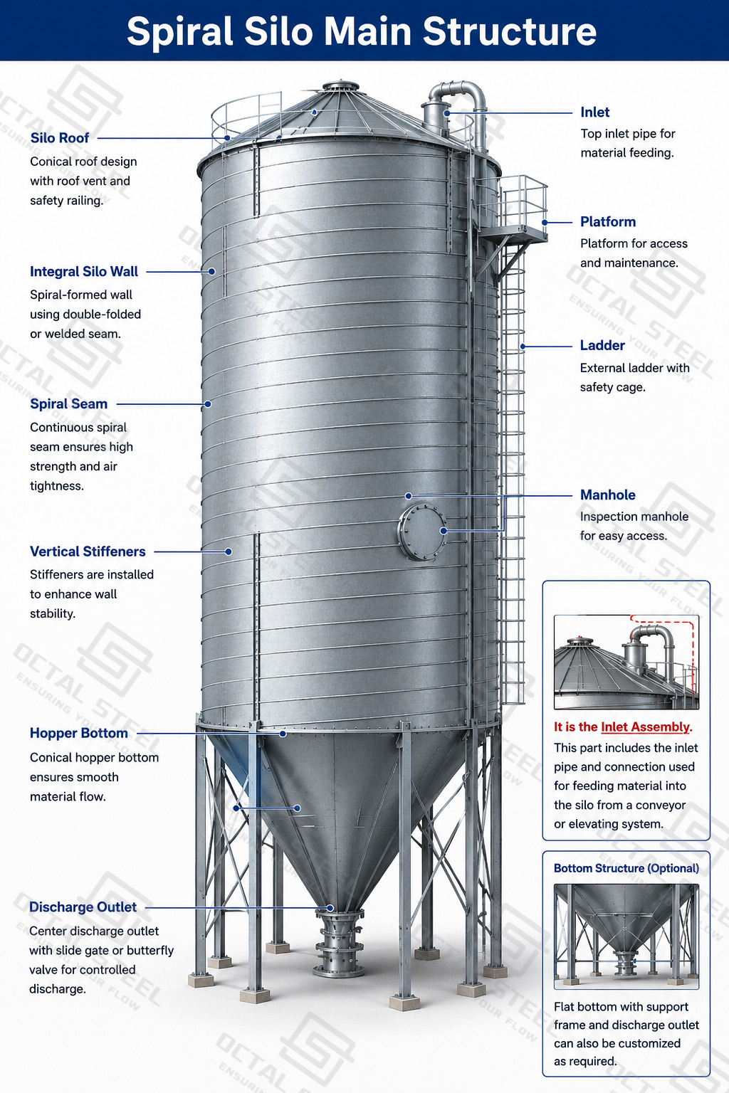
Main Structural Components
| Component | Main Function | Important Interface |
|---|---|---|
| Silo Roof | Encloses the stored material and supports roof-mounted equipment | Filling inlet, vent, filter, instruments and access |
| Integral Silo Wall | Contains the bulk solid and transfers shell loads | Openings, stiffeners and base connection |
| Spiral Folded Seam | Connects successive steel strips | Seam geometry and sealing condition |
| Vertical Stiffeners | Provide additional shell resistance where required | Roof, wall and foundation connections |
| Access Manholes | Permit inspection, cleaning and maintenance | Position, sealing and safe access |
| Flat or Hopper Bottom | Supports stored material and directs discharge | Outlet arrangement and reclaim equipment |
| Inlet Connection | Introduces material into the silo | Impact, wear, segregation and displaced air |
| Discharge Outlet | Transfers material to downstream equipment | Flow control, isolation and metering |
| Ladders and Platforms | Provide equipment and inspection access | Local safety requirements and maintenance space |
Download:Spiral Silo Forming Methods, Seam Design and Inspection Guide
The selected wall-forming method defines how the steel strips are joined, while the completed silo depends on the coordinated design of the roof, integral wall, stiffeners, bottom, openings and access systems. Each component must be matched to the stored material, filling and discharge duty, sealing requirements and maintenance access. Together, these elements form a complete storage structure rather than an isolated cylindrical shell.
Steel Material and Corrosion Protection
Steel material and corrosion protection for a spiral silo are selected from the stored product, operating temperature, moisture exposure, cleaning method and external environment. Galvanized steel coil is widely used for dry, non-corrosive bulk materials, while carbon steel, stainless steel or additional coating systems may be required for chemically active products, humid locations, elevated temperatures or hygiene-sensitive applications. The table below summarizes how typical operating conditions affect shell material and protection requirements.
| Operating Condition | Material or Protection Requirement |
|---|---|
| Dry, Non-Corrosive Powder | Galvanized steel may provide a practical general-purpose shell. |
| Coastal or Humid Environment | External coating and condensation control require project-specific review. |
| Chemically Active Material | Internal surface compatibility and corrosion protection must be confirmed. |
| Food or Hygiene-Sensitive Product | Surface cleanability, material compatibility and contamination risk must be evaluated. |
| Abrasive Filling Stream | Inlet deflectors and replaceable local wear liners may be required. |
| Elevated Product Temperature | Steel grade, sealant compatibility and thermal movement require confirmation. |
| Internal Washing or Wet Cleaning | Drainage detailing and internal corrosion protection become critical. |
The selected protection system must cover the complete storage envelope rather than the cylindrical wall alone. Roof panels, folded seams, stiffeners, fasteners, manholes, inlets, outlets and conveying connections require compatible materials and detailing, because untreated interfaces can become the principal locations for corrosion, moisture entry or product contamination.
Sealing and Storage Protection
The continuous spiral seam forms the main connection between adjacent steel strips and helps create an enclosed cylindrical wall. However, the storage protection of a spiral silo depends on the complete enclosure, including the roof connection, wall penetrations, manholes, filling pipes, vents, level instruments and discharge outlets. These interfaces must be sealed and detailed together to limit rainwater entry, uncontrolled moisture exchange and product leakage.
The required sealing level depends on the stored material and the operating process. Cement, fly ash and moisture-sensitive mineral powders require effective protection against external water and condensation, while pneumatic filling also requires a controlled route for displaced air through the vent filter. Grain storage may require ventilation and aeration, so the enclosure must protect the product without preventing the intended airflow. A sealed storage shell should therefore not be confused with a pressure vessel or a completely closed system.
Reliable storage performance requires regular inspection of the spiral seam, roof-to-wall joint, manhole seals, pipe flanges and discharge connections. Damaged sealant, loose connections or corrosion around openings can allow moisture to enter even when the main silo wall remains intact. Sealing details must therefore be selected according to the stored material, climate, filling method and maintenance conditions.
How Stored Material Determines Silo Configuration
A spiral silo must be configured from the actual behavior of the stored material rather than from its name alone. Bulk density determines stored mass, while flowability, moisture and storage time determine whether the material can discharge reliably or is likely to bridge, cake or remain on the silo floor.
| Material Property | Effect on Silo Configuration |
|---|---|
| Bulk Density | Determines stored mass, shell loading and usable capacity. |
| Flowability | Defines bottom type, outlet size and the need for flow assistance. |
| Moisture Content | Influences caking, corrosion and storage stability. |
| Particle Size and Fines | Affect segregation, dust generation and filter duty. |
| Abrasiveness | Determines wear protection at inlets, outlets and conveyors. |
| Storage Period | Influences consolidation and reclaim difficulty. |
Free-flowing grain may use gravity discharge, while cement, fly ash and fine mineral powder often require aeration, fluidization or multiple outlets. The final spiral steel silo configuration should therefore be based on representative material data and the required filling, storage and discharge conditions.
Bottom Configuration and Discharge System
The bottom configuration of a spiral silo is selected according to storage volume, material flowability, turnover frequency and required discharge rate. A flat-bottom structure is generally used for larger inventories, while a hopper-bottom structure directs material toward the outlet and is more suitable for frequent process discharge.
| Bottom Configuration | Typical Duty | Common Discharge Arrangement | Main Limitation |
|---|---|---|---|
| Flat Bottom | Large-volume or long-term storage | Aerated outlets, air slides, screw conveyors or mechanical reclaim | Residual material requires a defined reclaim system |
| Hopper Bottom | Frequent filling, batching or process buffering | Gravity outlet, gate, rotary valve, screw conveyor or air slide | Reliable discharge depends on material flowability and outlet design |
Download:Spiral Silo Material Flow, Bottom Selection and Discharge Guide
Fine powders such as cement and fly ash may require aeration or fluidization to prevent stable material above the outlet, while free-flowing grain and granules can use gravity discharge or mechanical conveyors. The final silo discharge system must be matched to the material, outlet size, required flow rate and downstream equipment.
Spiral Silo Applications and System Configuration
A spiral silo must be configured around the actual material-handling process rather than the storage volume alone. Cement and fly ash normally require pneumatic filling, controlled venting and flow-assisted discharge; dry-mortar materials require grade separation and accurate batching; grain requires aeration and temperature monitoring; bulk terminals require high-rate receiving, inventory control and coordinated load-out equipment.
| Application | Typical Stored Material | Main Process Duty | Typical Auxiliary Equipment |
|---|---|---|---|
| Cement and Fly Ash Storage | Cement, fly ash and supplementary cementitious materials | Receive powder and maintain stable discharge to batching, packing or loading | Vent filter, pressure relief valve, level sensor, aeration, air slide or screw conveyor |
| Dry Mortar and Mineral Processing | Cement, slag powder, lime powder, mineral filler and dried sand fractions | Separate material grades and supply controlled quantities to weighing and mixing | Diverter valve, dust collector, feeder, weigh hopper and conveying equipment |
| Grain and Feed Storage | Wheat, corn, rice and feed ingredients | Preserve product condition and provide controlled reclaim | Bucket elevator, distributor, aeration, temperature monitoring and sweep auger |
| Bulk Receiving and Load-Out | Cement, fly ash, grain or other suitable bulk solids | Receive, separate, store, weigh and load material at high throughput | Receiving conveyor, silo group, weighing system, loading spout and centralized controls |
Cement and Fly Ash Storage
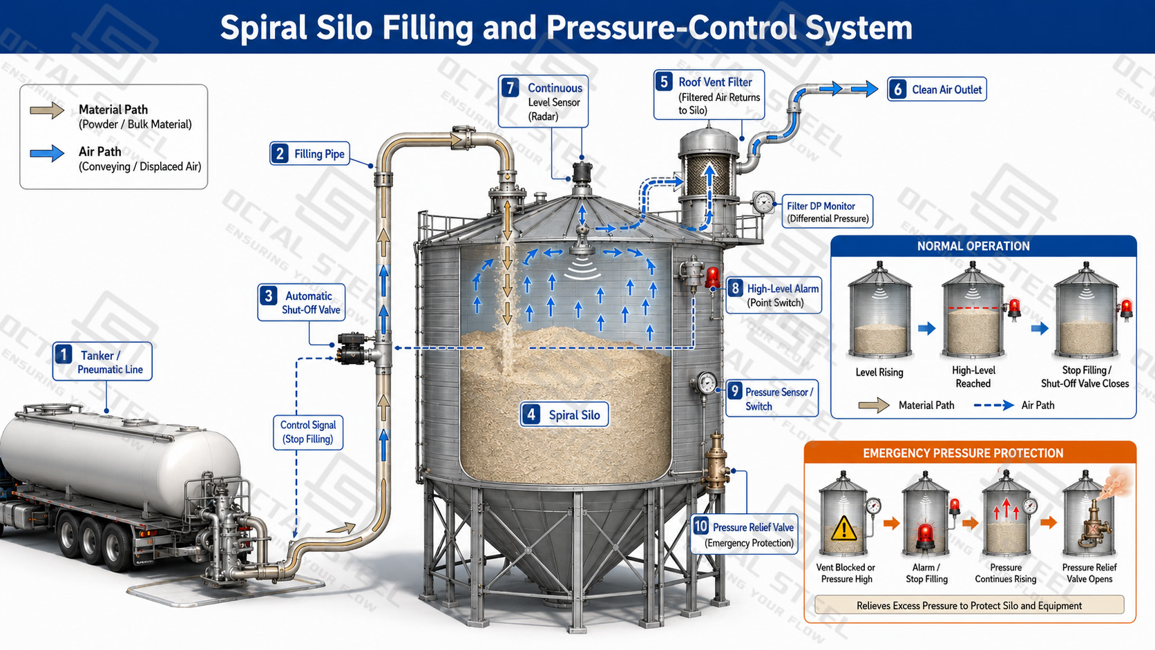
In a cement grinding plant, concrete batching plant or cement terminal, the silo is normally installed between pneumatic receiving and downstream weighing, packing or truck loading. Cement enters through a filling pipeline, displaced air passes through the roof filter, and the stored powder leaves through an aerated outlet connected to an air slide or screw conveyor.
A typical process route is:
Tanker or Process Filling → Spiral Silo → Aerated Discharge → Air Slide or Screw Conveyor → Weighing, Mixing or Packing
The filling pipeline, vent filter, pressure relief valve and high-level alarm must operate as one system. At the bottom, aeration is used to loosen consolidated powder and maintain a continuous feed to the downstream conveyor. Large flat-bottom silos may use several aerated zones and discharge outlets, while smaller process silos may use a hopper bottom with a controlled outlet.
Fly ash requires additional attention because pneumatic filling can temporarily aerate the powder and reduce its apparent bulk density. Level readings and tonne calculations should therefore use an agreed settled storage density rather than the density measured immediately after filling. Its fine particles also increase filter loading and may require more controlled fluidization at the outlet.
Dry Mortar and Mineral Processing
In a dry-mortar plant, spiral silos can be positioned between drying or grinding equipment and the batching system. Separate silos are normally assigned to cement, mineral filler, slag powder, lime powder or different dried-sand fractions to prevent cross-contamination and maintain recipe accuracy.
A typical process route is:
Drying, Grinding or Classification → Material Diverter → Spiral Silo → Controlled Feeder → Weigh Hopper → Mixer
The silo functions as a production buffer, allowing the upstream dryer, mill or classifier to operate independently from the downstream batch cycle. The discharge feeder must deliver a stable rate to the weigh hopper; irregular flow can extend weighing time, cause overshoot or interrupt mixer feeding.
For abrasive mineral materials, inlet elbows, impact areas and discharge outlets may require replaceable wear liners. Fine or moisture-sensitive powders require effective vent filtration and dry conveying air, while different material grades require positive diverter positioning and level-based filling interlocks.
Grain and Feed Storage
A grain storage silo is normally connected to a bucket elevator, top distributor and bottom reclaim conveyor. Grain enters through the roof distribution system, remains under monitored storage conditions and is discharged by gravity or a sweep-auger arrangement to milling, feed production or truck loading.
A typical grain route is:
Receiving Pit → Cleaning → Bucket Elevator → Spiral Silo → Gravity or Sweep Reclaim → Milling, Feed Production or Loading
Unlike cement storage, grain storage focuses on product temperature, moisture migration and aeration. Perforated floors or aeration ducts distribute air through the grain mass, while temperature cables identify developing hot spots. Roof ventilation allows warm, moisture-laden air to leave the silo.
Transfer points require dust collection, and the reclaim system must avoid leaving large stagnant zones. Grain dust and accumulated material also create fire, explosion and engulfment hazards, so access, housekeeping and maintenance procedures form part of the complete storage system.
Bulk Receiving and Load-Out Terminals
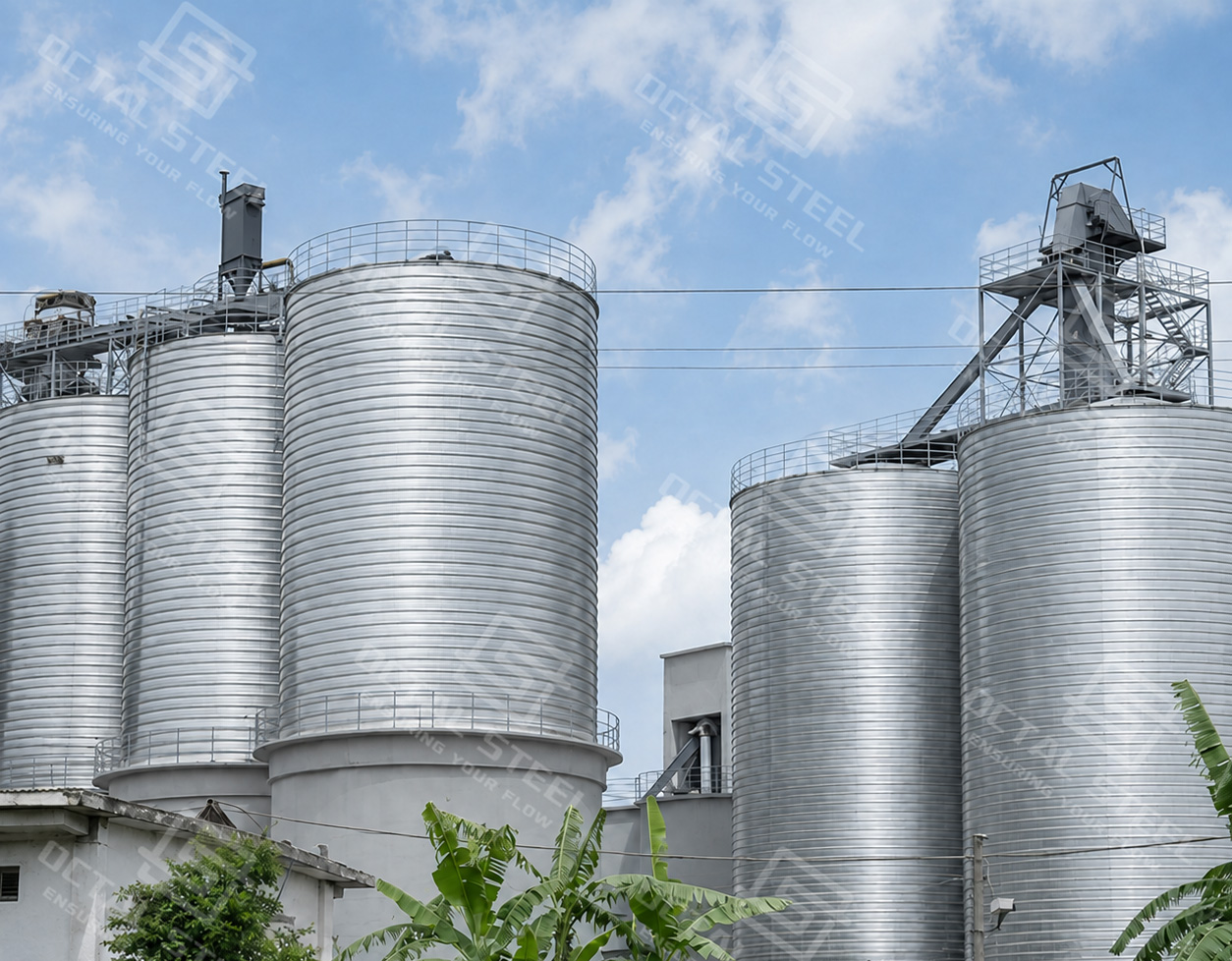
At a cement, fly ash or grain terminal, several spiral silos may be arranged as one storage group between receiving and dispatch. Material may arrive by tanker, truck, rail or plant conveyor and leave through a weighing and loading system.
A typical terminal route is:
Truck, Rail or Process Receiving → Transfer Conveyor or Pneumatic Line → Assigned Silo → Weighing System → Truck or Process Load-Out
The practical design issue is often not silo volume but the coordination of receiving and loading rates. A terminal must define which silos can be filled and discharged simultaneously, how different grades are routed, and how cross-contamination is prevented when transfer equipment is shared.
Each silo requires reliable level indication and material identification. The discharge conveyor, weigh hopper and loading spout must match the required load-out rate, while dust collection is required at receiving pits, transfer points and truck-loading stations. Centralized controls should prevent material from being routed to the wrong silo and stop filling when the assigned silo reaches its high-level limit.
The final spiral steel silo configuration should therefore be selected from the complete operating route: how the material is received, how long it remains in storage, how it is discharged and which downstream equipment must be supplied continuously.
OCTAL STEEL Supply Scope and Advantages
OCTAL STEEL can supply a spiral steel silo as an individual storage unit or as part of an integrated bulk-material handling system. The final scope is configured around the stored material, filling method, discharge duty and site interfaces.
- Complete silo structure: shell, roof, flat or hopper bottom, access openings, ladders and platforms.
- Project-specific steel selection: galvanized steel coil, carbon steel, stainless steel or specified corrosion-protection systems.
- Material-handling integration: filling connections, vent filters, pressure relief, aeration or fluidization, and discharge equipment.
- Auxiliary equipment coordination: level monitoring, temperature measurement, conveyors, air slides, screw conveyors and operating interlocks.
- Defined project interfaces: layout, equipment connections, installation references, operation documents and clear division of civil work, utilities and external conveying systems.
OCTAL STEEL combines the silo structure with the required filling, storage and discharge equipment so that the complete system is matched to the actual material properties and production process.
FAQ
Q1: Can the same spiral silo configuration store cement, fly ash and grain?
A1: The steel shell may use the same forming principle, but the process equipment is different. Cement and fly ash normally require pneumatic filling, vent filtration and flow-assisted discharge, while grain requires aeration, temperature monitoring and mechanical reclaim.
Q2: How is spiral silo capacity converted from cubic metres to tonnes?
A2: Stored mass is calculated from usable silo volume and the agreed design bulk density. Freeboard, filling profile, bottom geometry and residual material must be deducted from the geometric volume, and aerated density should not be used as settled storage density.
Q3: When should a spiral silo use a flat bottom or a hopper bottom?
A3: Flat bottoms suit larger inventories but require a defined reclaim system. Hopper bottoms support more direct discharge, although the hopper angle, outlet size and flow aids must still match material flowability, consolidation and the required discharge rate.
Q4: What determines the airtightness of a spiral steel silo?
A4: Airtightness depends on the complete storage enclosure, not the folded seam alone. The spiral joint, roof connection, manholes, filling pipes, vent filter, instrument penetrations and discharge outlets must all use compatible sealing details.