Your Responsible Supplier Partner for Oil and Gas Products.

Sucker Rod Couplings
Recent Products


Rencent Articles






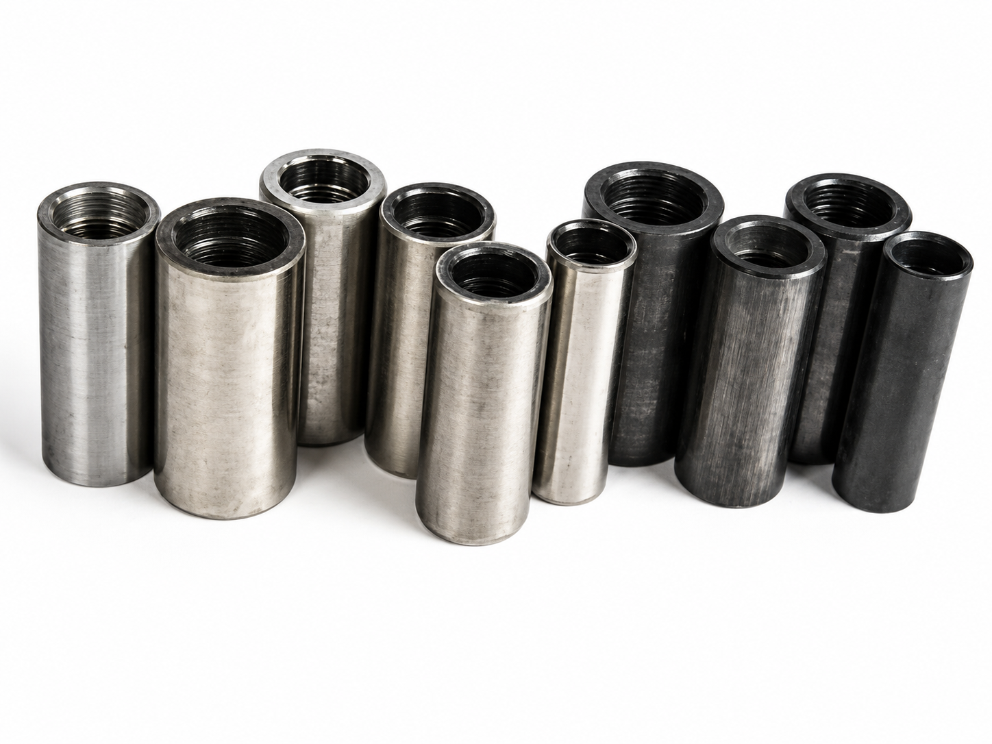
Sucker Rod Couplings
Rod Sizes: 5/8″, 3/4″, 7/8″, 1″, 1-1/8″
Standard: API Spec 11B requirements where specified
Material / Class: Carbon or alloy steel; Class T or Spray Metal (SM) as specified
Connection: Internal box threads matched to sucker rod pin connections
Coupling Types: Full-size, Slim-hole, Standard and Crossover / Sub-Coupling
Inspection: Dimensions, thread gauging, surface condition, marking and traceability as specified
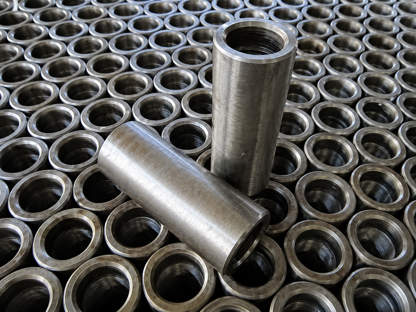
Sucker rod couplings are threaded steel connection components installed between adjacent sucker rods or compatible rod-string members in an oilfield rod-lift system. Each coupling receives the externally threaded pin ends of the adjoining rods and becomes part of the load path that transfers reciprocating motion and cyclic axial load from the surface pumping unit toward the downhole pump. Conventional sucker-rod connections therefore depend not only on coupling strength, but also on correct rod size, box thread, outside diameter, shoulder contact and connection compatibility.
OCTAL STEEL provides oilfield sucker rod coupling configurations for new rod strings, replacement work and project-specific rod-lift assemblies. Full-size, slim-hole, Class T, spray-metal and crossover configurations can be specified according to the applicable rod size and service requirement, with API Spec 11B requirements where specified. The coupling should be selected together with the sucker rod or pony rod rather than as an independent threaded fitting, because coupling OD, thread geometry, material condition and existing rod-string compatibility all affect field performance.
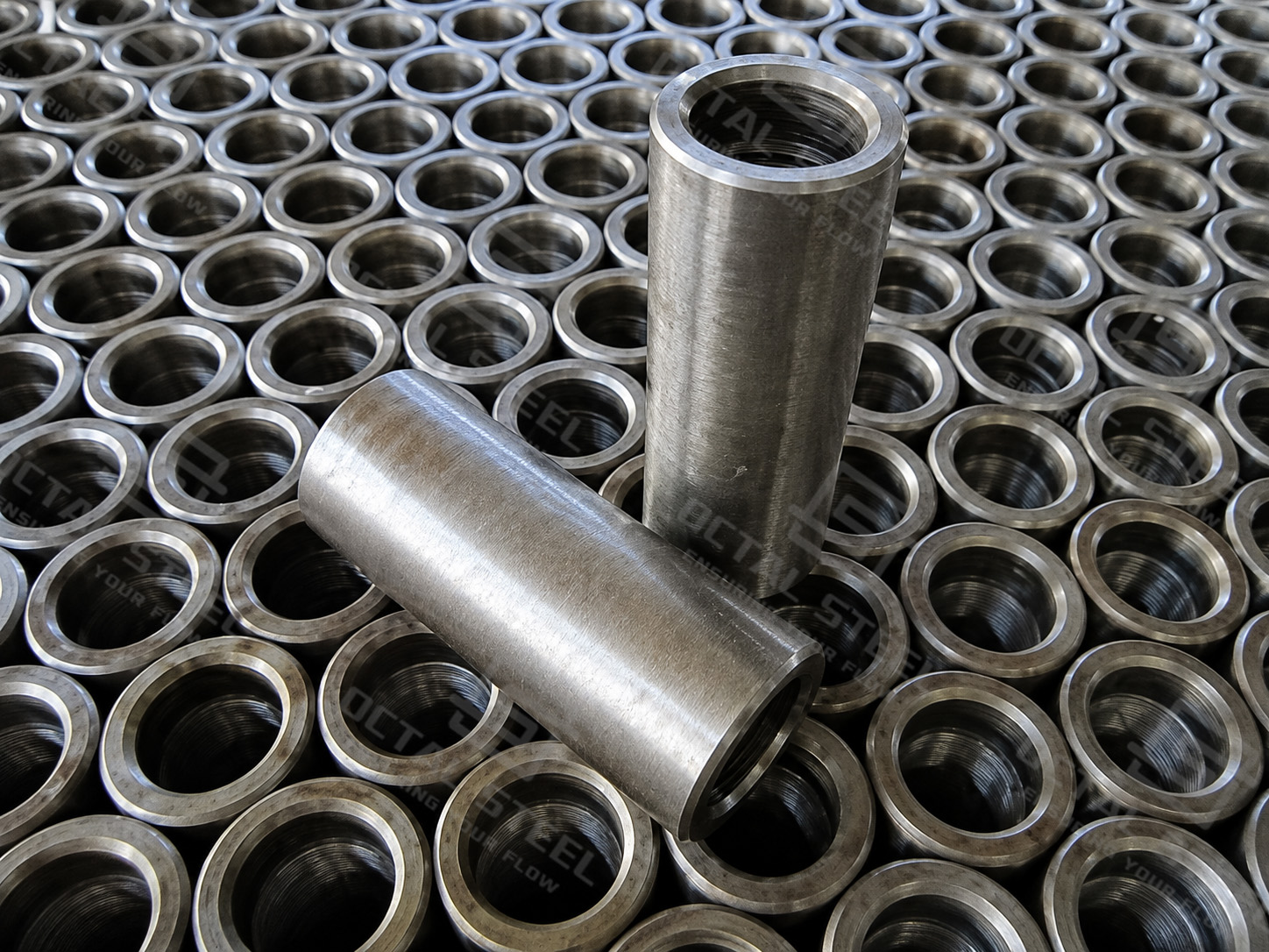
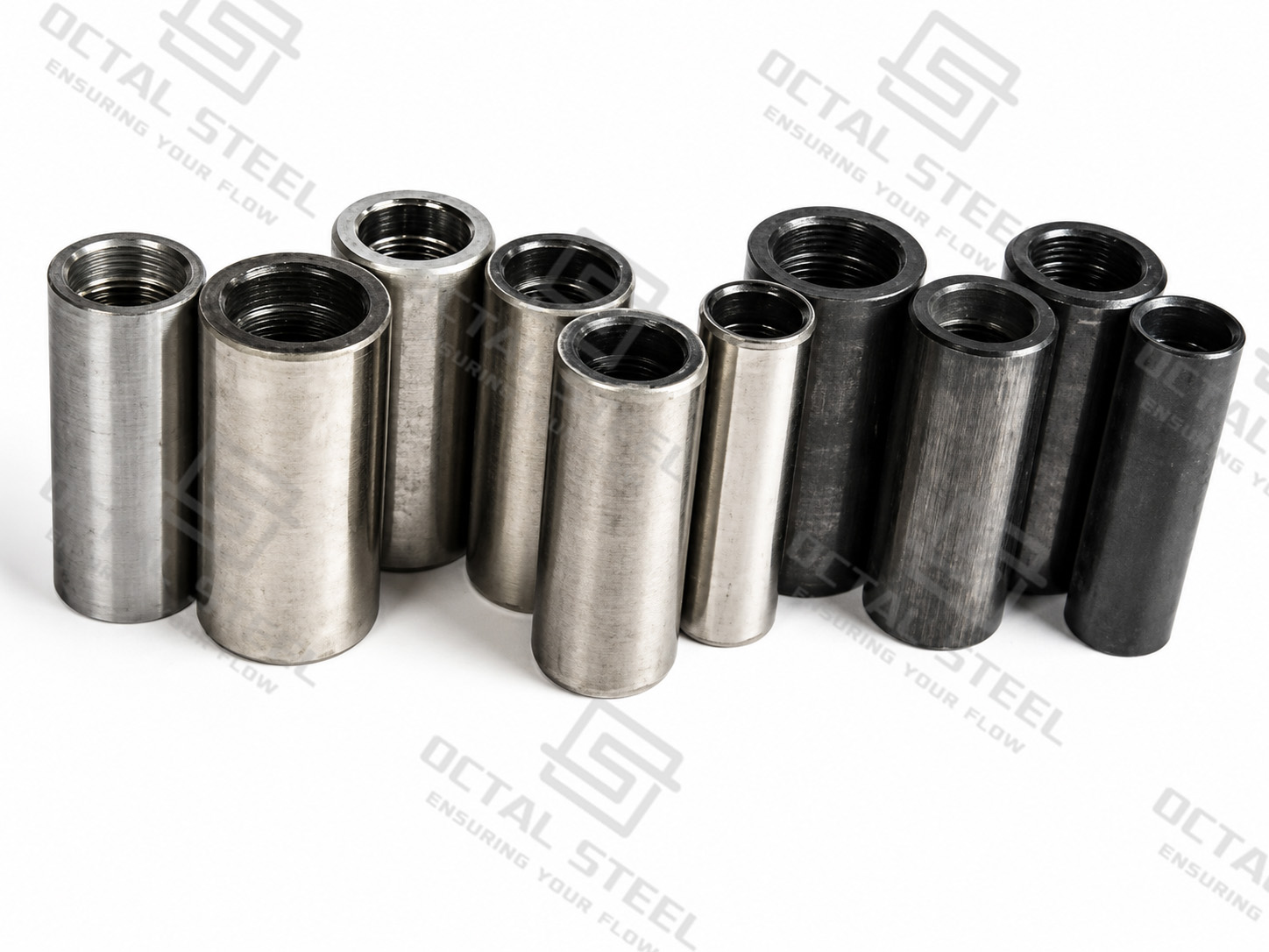
Sucker Rod Coupling Specifications and Ordering Data
The most important ordering information is the nominal sucker rod size, corresponding rod pin connection, required coupling OD configuration and coupling class. Common API rod-body sizes extend from 5/8 in. through 1-1/8 in.; the nominal rod size is not the same as the mating thread size because the forged rod end contains a larger shouldered pin connection.
| Specification Item | Representative Configuration |
|---|---|
| Product | Sucker Rod Coupling |
| Applicable Standard | API Spec 11B requirements where specified |
| Nominal Rod Sizes | 5/8, 3/4, 7/8, 1, and 1-1/8 in. |
| Connection | Internally threaded box connection for sucker rod pin |
| Coupling OD | Full-size or slim-hole |
| Coupling Classes | Class T / Spray Metal SM where specified |
| Material | Carbon steel or alloy steel according to coupling class and service requirement |
| Related Types | Standard sucker rod coupling, sub-coupling / crossover coupling, project-specific rod-string coupling |
| Service | Sucker rod pumping and rod-lift systems |
| Inspection | Dimensions, thread/gauge condition, surface condition, marking and traceability as specified |
These are representative product boundaries rather than fixed inventory. Final sucker rod coupling dimensions, material, class and inspection requirements should follow the applicable API Spec 11B connection requirements, purchase specification and matching sucker rod connection data.
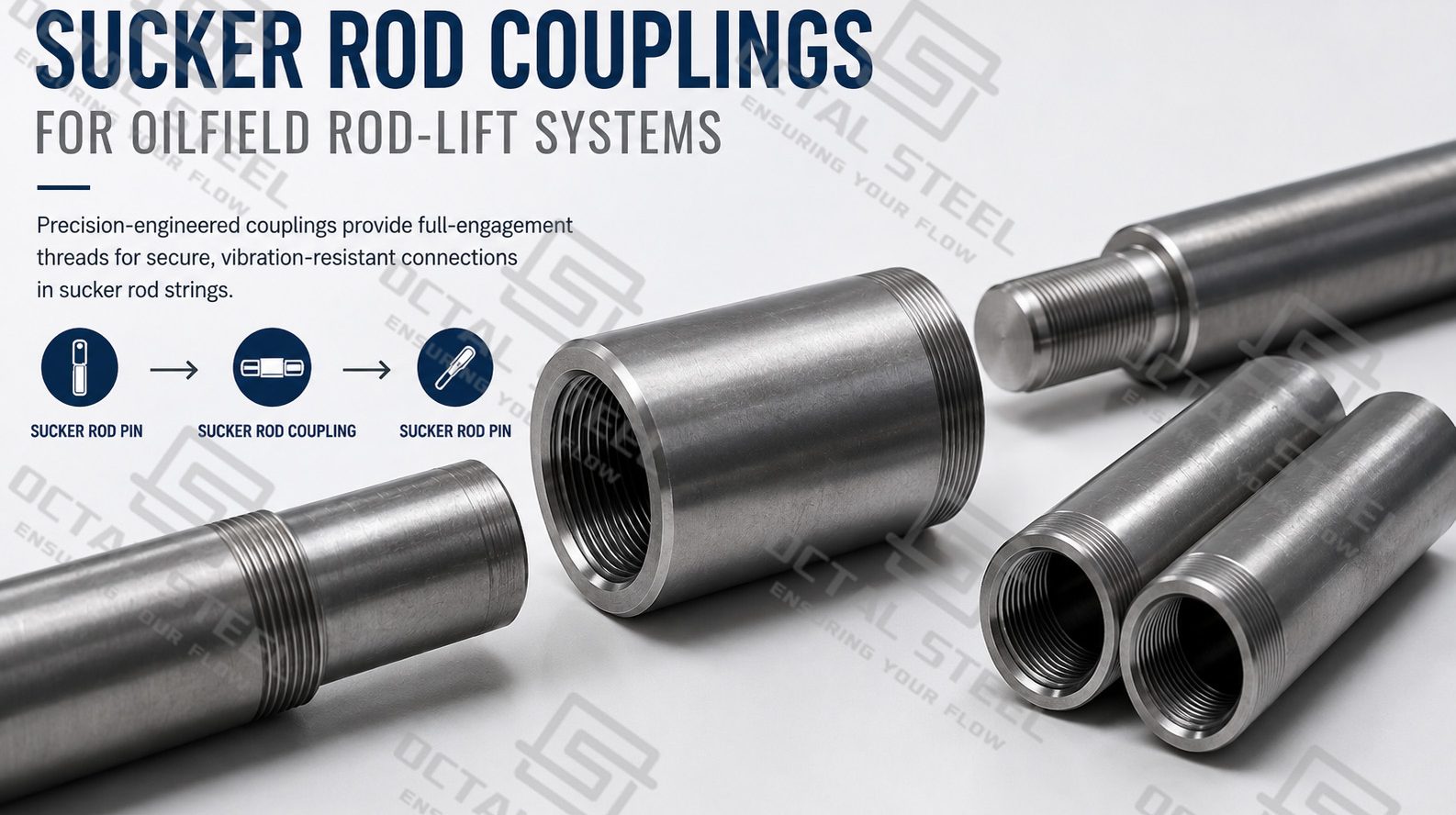
How a Sucker Rod Coupling Connects the Rod String
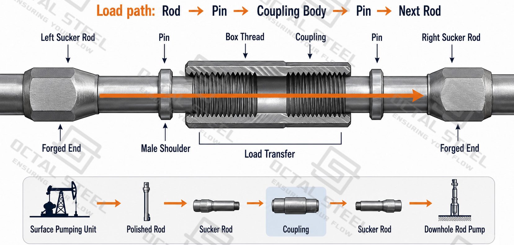
A sucker rod coupling is installed between two sucker rods. Each sucker rod has a male threaded pin at its end, while the coupling has female box threads at both ends. One rod screws into one end of the coupling and the next rod screws into the opposite end, forming one continuous rod string.
Rod connection:
Sucker Rod Pin → Coupling Box Thread → Coupling Body → Coupling Box Thread → Next Sucker Rod Pin.
When the surface pumping unit moves the polished rod up and down, the same reciprocating motion travels through every sucker rod connection and coupling to the downhole pump.At each joint, the load passes from the first rod pin into the coupling body and then into the pin of the next rod. The coupling is therefore both a threaded connector and a load-carrying part of the sucker rod string.
The connection must match more than the nominal rod diameter. The sucker rod pin, coupling box thread, shoulder geometry and coupling size must correspond to the same connection system. A coupling with the wrong thread or dimensions may screw on only partially, fail to seat correctly, or create an unsuitable load condition at the joint.
In an actual rod string, this same connection is repeated many times:
Polished Rod → Sucker Rod → Coupling → Sucker Rod → Coupling → Pony Rod / Sucker Rod → Downhole Pump.
This makes connection compatibility especially important during replacement and workover operations, where a new coupling may need to match sucker rods already installed in the well.
Sucker Rod Coupling Sizes and Connection Dimensions
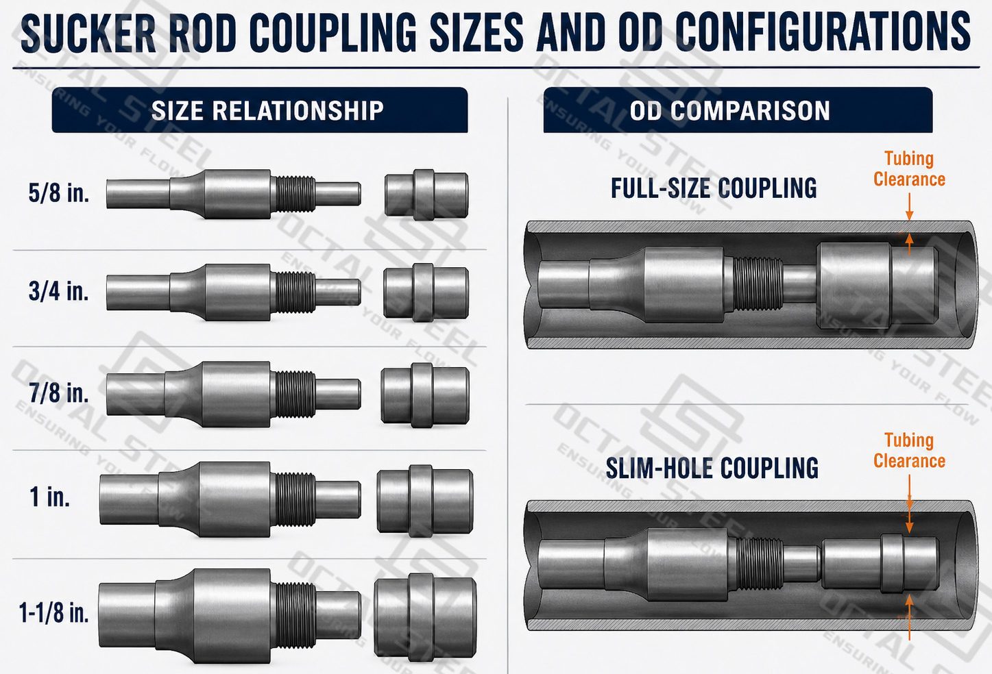
The nominal sucker rod coupling size normally follows the rod section in which it is installed. The connection itself is larger than the rod body because the forged end incorporates the wrench area, shoulder and pin.
Representative connection relationships are shown below. OCTAL STEEL’s existing API 11B sucker-rod data uses the same rod-size-to-pin system, while published industry coupling data shows corresponding full-size coupling outside diameters.
| Nominal Rod Size | Representative Pin / Internal Thread | Full-Size Coupling OD |
|---|---|---|
| 5/8 in. | 15/16 in. | 1.500 in. / 38.1 mm |
| 3/4 in. | 1-1/16 in. | 1.625 in. / 41.3 mm |
| 7/8 in. | 1-3/16 in. | 1.812 in. / 46.0 mm |
| 1 in. | 1-3/8 in. | 2.187 in. / 55.6 mm |
| 1-1/8 in. | 1-9/16 in. | 2.375 in. / 60.3 mm |
The table is useful for preliminary sucker rod coupling size selection, but nominal size should not be used as the only ordering reference. Thread/gauge requirements, coupling class, API edition and the adjoining rod connection still need to be confirmed.
Full-Size Sucker Rod Coupling
A full-size sucker rod coupling uses the standard outside-diameter envelope associated with the corresponding sucker rod connection. It is generally the basic configuration where the available tubing clearance does not require a reduced coupling OD.
Its larger outside diameter, however, becomes an important design input in deviated wells because the coupling normally projects farther radially than the sucker rod body. Where the rod string contacts the production tubing, the coupling may become one of the main contact points.
Slim-Hole Sucker Rod Coupling
A slim-hole sucker rod coupling reduces the coupling outside diameter to provide additional clearance between the rod string and production tubing or other restricted well geometry.
The reduced OD does not mean the coupling can be selected on clearance alone. The rod size, connection, rod-string load, tubing ID and expected contact condition still need to be reviewed together. OCTAL STEEL’s existing sucker rod engineering content follows this same selection logic for full-size and slim-hole couplings.
Class T and SM Sucker Rod Couplings
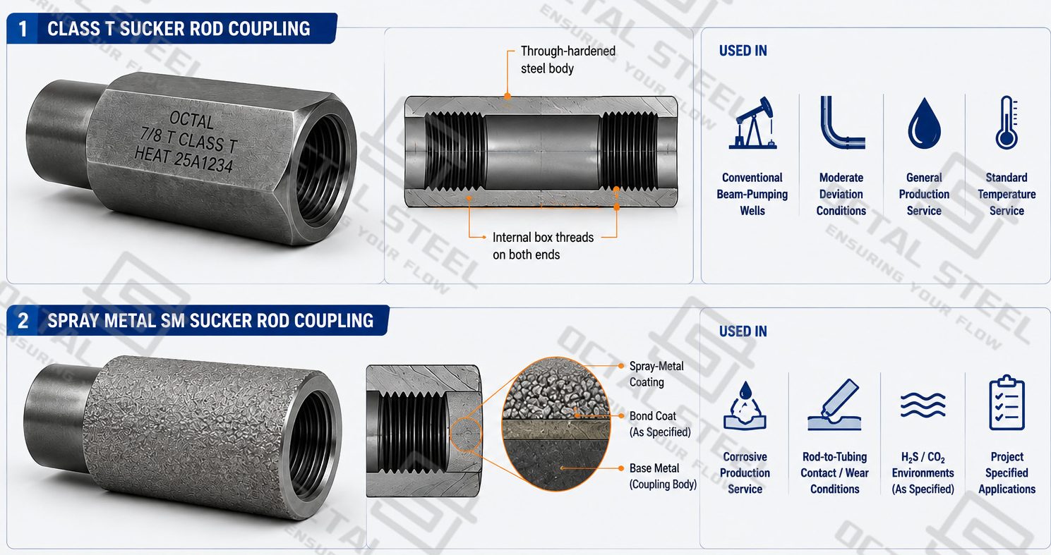
Coupling class influences both the basic mechanical construction and the surface condition exposed to rod-to-tubing contact and the produced-fluid environment.
Class T Sucker Rod Coupling
Class T sucker rod couplings are through-hardened steel couplings intended to provide the mechanical properties required by the specified rod-string connection. They represent a conventional steel coupling configuration and are used where the selected material class and operating environment are suitable. Published industrial coupling specifications identify Class T as a through-hardened coupling class.
The practical purchasing point is not simply to request “Class T.” The buyer also needs to identify the matching rod size, connection, coupling OD and well service.
Spray Metal SM Sucker Rod Coupling
An SM sucker rod coupling uses a spray-metal outer-surface configuration over the coupling body. The purpose of this configuration is to provide additional surface performance where coupling wear and corrosive exposure are significant selection factors. Industrial product literature distinguishes SM from the conventional through-hardened Class T configuration specifically through its sprayed-metal surface system.
The required coating system and acceptance criteria should follow the applicable API/project specification rather than an assumed universal coating thickness or hardness.
Sub-Couplings and Crossover Connections
Not every rod string uses the same connection size throughout its full length.
A conventional sucker rod coupling has the same box connection at both ends, allowing two compatible rods of the same connection system to be joined. A sub-coupling, also called a crossover coupling, uses different box connection sizes at its two ends so that compatible rod-string components with different connection sizes can be joined.
This becomes relevant in tapered or mixed-diameter rod strings.
For example:
1 in. rod section → transition → 7/8 in. rod section.
The transition component must be identified from the actual connections on both sides. Ordering a coupling simply as “1 in. × 7/8 in.” without confirming the pin and thread system can leave important compatibility information undefined.
Crossover connections are therefore better specified by:
Upper component → nominal size → pin connection → lower component → nominal size → pin connection → applicable coupling configuration.
Download:Sucker Rod Coupling Technical Reference Sheet.pdf
Sucker Rod Coupling Selection by Operating Condition
A coupling that connects correctly on the bench may still be unsuitable for the downhole operating condition. The main selection variables change according to where and how the rod string operates.
Conventional Beam-Pumping Wells
In a conventional sucker rod pumping system, the coupling repeatedly transfers the changing axial load between adjoining rods during every pumping stroke.
The basic selection sequence is:
Rod size → pin/thread → coupling size → Class T or SM requirement → full-size/slim-hole configuration.
Load compatibility and connection condition remain more important than selecting a coupling from diameter alone.
Deviated Wells and Rod-to-Tubing Contact
Well deviation introduces side contact in addition to axial loading. Because the coupling has a larger OD than the sucker rod body, it can contact the production tubing as the string moves through a deviated section. 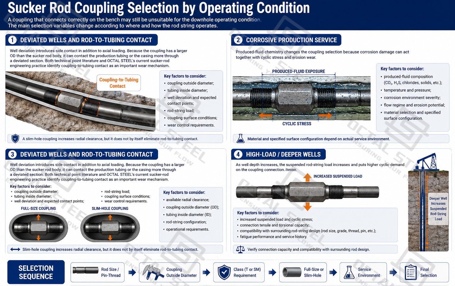
Corrosive Production Service
Produced-fluid chemistry changes the coupling selection because corrosion damage can act together with cyclic stress and surface wear.
Where produced water, CO₂, H₂S, chlorides or another specified corrosive environment is present, the material and surface system should be selected from the actual service data. Describing every SM or alloy coupling as universally “corrosion resistant” is not technically sufficient; stress, material condition, corrosion mechanism and the project corrosion-control program need to be considered together.
High-Load Rod Strings
Deeper pump settings, higher suspended rod-string weight and increased pump load can raise the cyclic force carried through the threaded connections.
In these applications, the coupling must be matched to the surrounding rod design. Installing a higher-strength rod without confirming the connection and coupling configuration does not automatically create a higher-capacity rod string.
Replacement Couplings and Existing Rod-String Compatibility
Replacement work is one of the most specification-sensitive uses of an API 11B sucker rod coupling.
For an existing rod string, confirm:
Rod Size → API Edition / Connection Data → Pin Dimensions → Coupling Type → Thread Condition → Gauge Compatibility → Existing Component Condition.
For replacement work, the new coupling should be checked against the existing sucker rod string for rod size, pin/thread configuration, coupling type, thread condition and gauge compatibility before release.If the existing coupling has shoulder wear, damaged threads, corrosion or uncertain dimensional history, those conditions become part of the replacement decision.
Sucker Rod Coupling Material and Mechanical Service
Sucker rod couplings are commonly manufactured from selected carbon or alloy steel according to the specified coupling class and service requirement. Published industrial specifications use both carbon- and alloy-steel routes for standard couplings, while special-service designs may apply different materials or surface systems.
Material selection has to support three simultaneous demands:
Cyclic load transfer.
The coupling repeatedly carries load through the threaded rod connection.
Thread and shoulder integrity.
The connection geometry has to maintain the intended mechanical contact and preload condition.
Downhole surface exposure.
The outside surface may experience produced-fluid exposure and repeated contact with production tubing.
For this reason, sucker rod coupling material should not be specified independently from coupling class and operating condition. Two couplings with the same nominal dimensions may have different material routes or surface configurations for different rod-lift environments.
Sucker Rod Coupling Selection by Well Condition
The correct sucker rod coupling is determined first by the mating sucker rod connection, but operating conditions can change the required coupling OD, material, surface configuration and service class. These factors become particularly important where the rod string operates with limited tubing clearance, repeated tubing contact, corrosive produced fluids or higher cyclic loading.
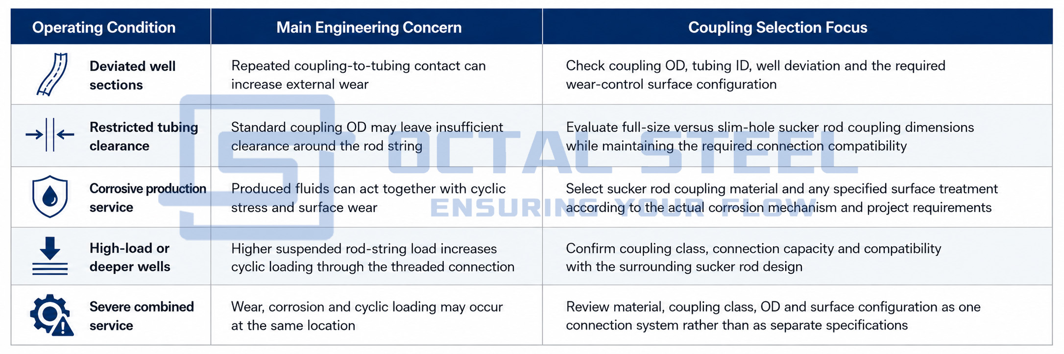
A reduced coupling OD can improve clearance, while a different material or surface system can address a particular service requirement, but none of these changes replaces correct thread matching. The sucker rod pin, coupling box thread, nominal rod size and applicable connection specification remain the starting point for every selection.
For this reason, Class T, SM, full-size and slim-hole couplings should be treated as configuration options within the complete rod-string design, rather than as interchangeable product grades selected from a single operating parameter.
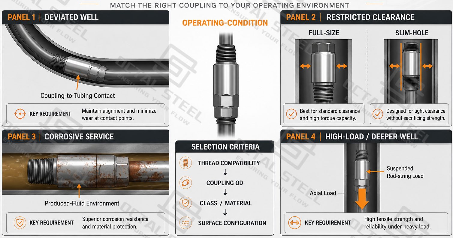
Sucker Rod Coupling Applications
Sucker rod couplings are used to assemble separate rod components into a continuous load-carrying string between the surface pumping equipment and the downhole rod pump. Their application depends on where a connection is required in the rod string and whether the project involves a new installation, a length-adjustment section, a diameter transition or an existing string.
New Sucker Rod String Assembly
In a new rod-lift installation, couplings connect consecutive sucker rods as the string is assembled to the required installed depth. Each connection must match the rod pin and maintain the mechanical load path through the complete sucker rod string.
The coupling schedule is therefore coordinated with the rod schedule so that each rod section has the correct mating connection.
Pony Rod Integration
A pony rod is inserted where a short length adjustment is required within the rod string. Because it remains a load-carrying member, its threaded ends must connect through couplings that match the adjacent sucker rod section.
The coupling in this position does not perform the length adjustment itself; it provides the compatible threaded connection that allows the pony rod to become part of the continuous rod string.
Tapered and Multi-Diameter Rod Strings
Tapered rod strings use different sucker rod diameters at different depths. Standard couplings are matched to the rod size within each section, while a sub-coupling or crossover coupling may be required where two different connection sizes meet.
The transition should be defined from the actual pin connections on both sides rather than only from the nominal rod-body diameters.
Workover and Rod Replacement
During a workover, a new coupling may need to connect with an existing sucker rod, pony rod or replacement section already in service.
In this case, nominal rod size alone is not sufficient. The existing pin/thread configuration, connection dimensions, applicable API specification or edition, thread condition and component wear need to be confirmed before the replacement coupling is selected.
This makes replacement work different from a completely new rod-string assembly: the new component has to fit an existing connection system whose dimensions and service condition are already fixed.
Download:Sucker Rod Coupling Selection Inspection RFQ Guide.pdf
Sucker Rod Coupling Project Supply and Technical Support
OCTAL STEEL supplies sucker rod couplings as part of a coordinated rod-string component system rather than as isolated threaded parts. Depending on the project scope, couplings can be matched with sucker rods, pony rods, polished rods, sinker bars and other specified rod-lift components so that connection size, thread configuration, coupling class and service condition are reviewed together.
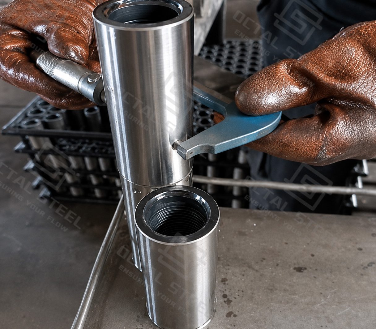
For new installations, workover programs and replacement orders, OCTAL STEEL can support the technical confirmation of the coupling before production and shipment. This reduces the risk of receiving a coupling with the correct nominal rod size but an incompatible pin/thread system, outside diameter or service configuration.
Project Support Can Include
- Connection matching:confirmation of sucker rod size, pin/thread configuration, coupling type and mating rod-string component.
- Coupling configuration review:full-size or slim-hole selection, Class T or SM requirement, and sub-coupling/crossover connection where specified.
- Service-condition coordination:review of tubing clearance, rod-string loading, produced-fluid environment and replacement conditions when these affect coupling selection.
- Inspection and traceability:dimensional inspection, thread gauging, material identification, product marking and lot-based traceability according to the specified project requirements.
- Documentation support:preparation of applicable inspection records, material documentation, packing information and other project-required release documents.
- Packing and shipment preparation:thread protection, identification and packing arrangements designed to protect finished connections during handling and transportation.
FAQ
Q1: What is a sucker rod coupling used for?
A sucker rod coupling connects the threaded pin ends of adjacent sucker rods or compatible rod-string members and transfers cyclic load through the joint during operation of the rod-lift system.
Q2: How do I select the correct sucker rod coupling size?
Start with the nominal sucker rod size, then confirm the corresponding pin/thread connection, coupling OD, coupling class and applicable API/project connection data. Nominal rod diameter alone is not enough.
Q3: What is the difference between full-size and slim-hole sucker rod couplings?
A full-size coupling uses the normal connection envelope, while a slim-hole coupling has a reduced outside diameter to increase clearance in restricted tubing or well geometry. The final choice also depends on load and connection compatibility.
Q4: Can a new API 11B sucker rod coupling be installed on an existing rod string?
Not automatically. For replacement work, confirm the API edition or connection dimensions, rod pin, coupling type, thread condition and gauge compatibility before assuming interchangeability. OCTAL STEEL’s current sucker-rod engineering data specifically identifies legacy/new connection compatibility as a replacement control point.