Your Responsible Supplier Partner for Oil and Gas Products.

Check Valve
Recent Products

Rencent Articles






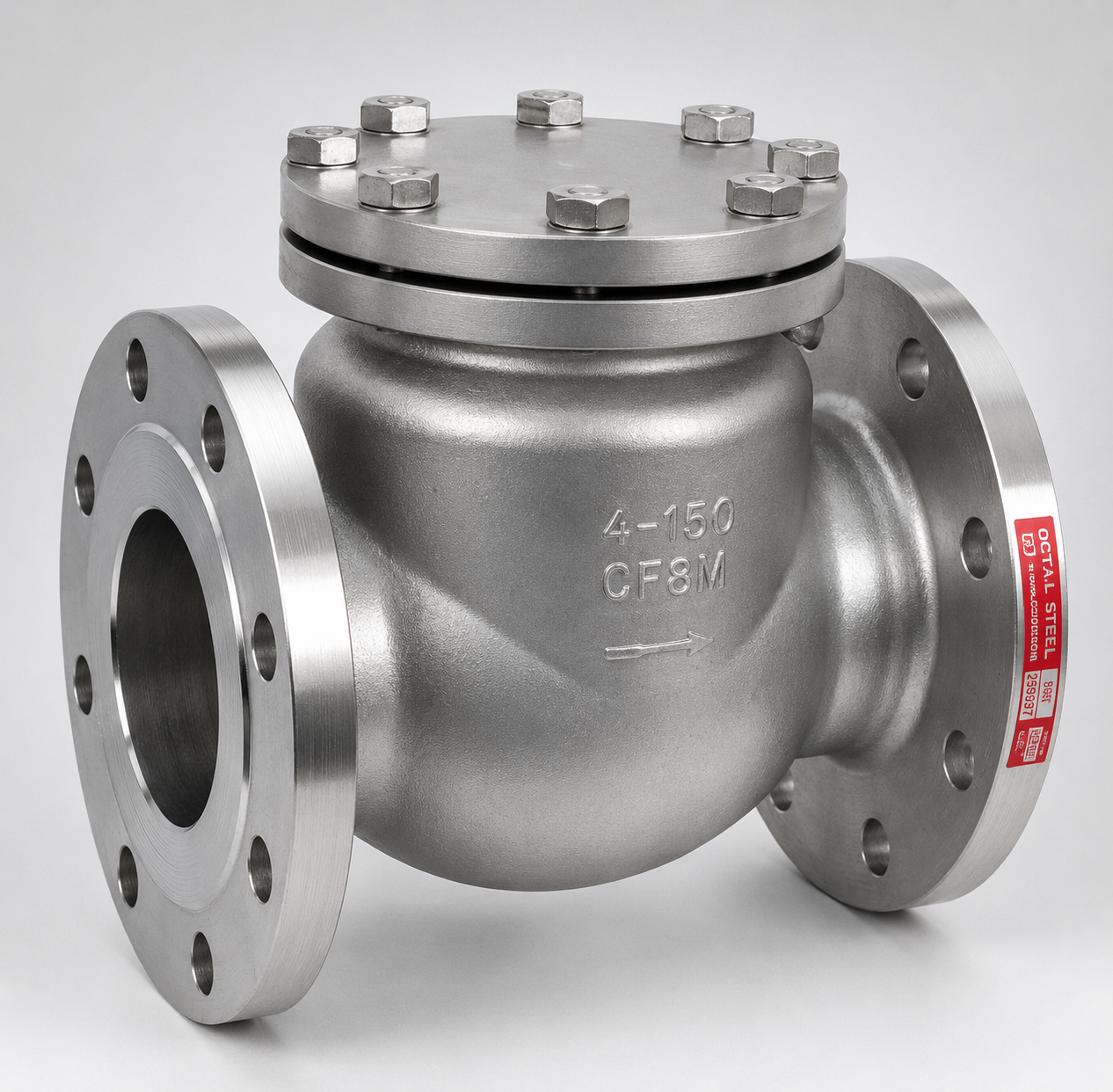
Check Valve
Valve Types: Swing, dual plate, axial flow and pressure seal check valves
Size Range: DN15–DN1500 / NPS 1/2–60, depending on configuration
Pressure Range: PN10–PN420 / Class 150–2500
Operation: Automatic, driven by forward and reverse differential pressure
Applications: Pump discharge, steam, compressor and process piping
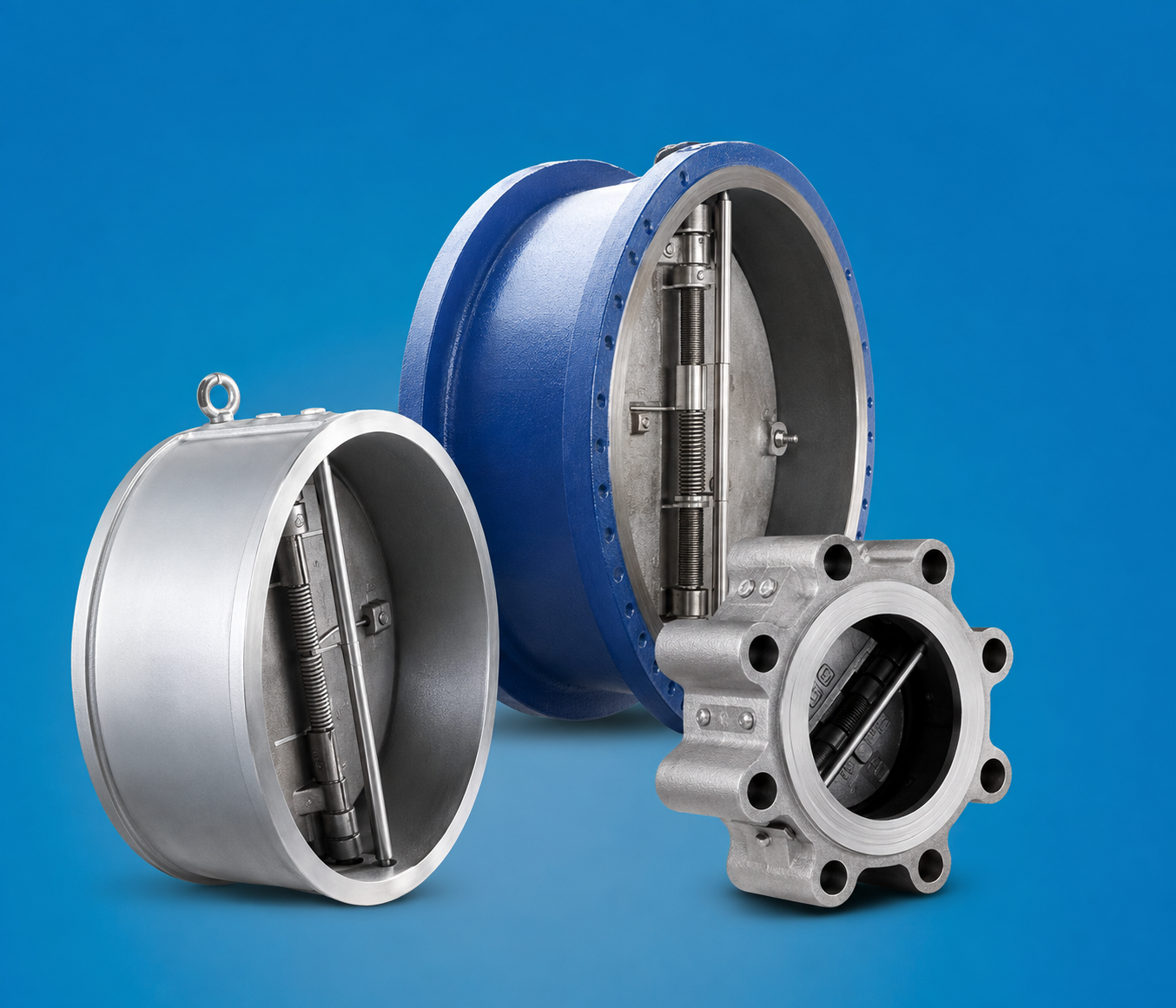
Check Valve uses a carbon steel, alloy steel or stainless steel pressure body with a disc, plate or guided closure element to prevent reverse flow in industrial piping systems. It operates automatically through the pressure difference across the valve: forward flow moves the closure element away from the seat, while decreasing or reversing flow allows gravity, spring force or differential pressure to return it to the sealing position. Main industrial configurations include swing check valve, dual plate check valve, axial flow check valve and pressure seal check valve, each using a different closure movement and body arrangement to control flow reversal.
For industrial service, selecting a check valve involves more than matching the valve size to the pipeline. Normal flow velocity must be sufficient to keep the closure element stable in the open position, while closure travel, moving mass, spring or gravity force and the rate of flow deceleration affect how quickly the valve returns to the seat. These factors influence pressure drop, disc or plate stability, reverse velocity and valve-slam risk, especially during pump shutdown, compressor trip or rapid process changes. A design with low steady-flow resistance is therefore not automatically the best choice for a system that requires faster closing response.
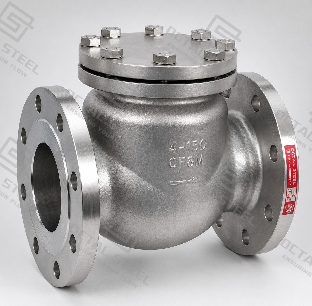
OCTAL STEEL supplies industrial steel check valves in swing, dual plate, axial-flow and pressure-seal configurations for refinery, chemical, power, steam, pump-discharge and other process piping duties. Available configurations use carbon steel, alloy steel or stainless steel pressure-boundary materials with flanged, butt-welded, wafer, threaded or socket-welded connections depending on valve type. Final selection should consider the operating medium, pressure and temperature, allowable pressure loss, installation orientation, expected flow-decay condition, applicable valve standard and project inspection requirements.
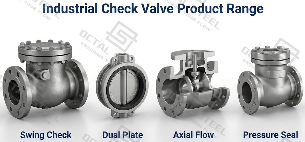
Industrial Check Valve Product Range
Industrial check valves are available in swing, axial flow, pressure seal and dual plate configurations for different line sizes, pressure ratings and piping arrangements. Carbon steel, alloy steel and stainless steel body materials can be matched to the service condition, while flanged, butt-welded, threaded, socket-welded and wafer connections are selected according to valve type and installation requirements. The available range varies by configuration, so final selection should confirm the design standard, material, pressure-temperature rating, end connection and operating condition.
| Check Valve Configuration | Reference Size Range | Reference Pressure Range | Main Materials | Connections | Operation |
|---|---|---|---|---|---|
| Swing Check Valve | DN15–DN1500 / NPS 1/2–60 | PN10–PN250 / Class 150–2500 | Carbon steel, alloy steel, stainless steel | Flanged, butt-welded, threaded, socket-welded | Automatic |
| Axial Flow Check Valve | DN50–DN1200 | PN10–PN250 / Class 150–1500 | Carbon steel, alloy steel, stainless steel | Flanged, butt-welded | Automatic |
| Pressure Seal Check Valve | DN50–DN600 / NPS 2–24 | PN10–PN420 / Class 150–2500 | Carbon steel, alloy steel, stainless steel | Flanged, butt-welded | Automatic |
| Dual Plate Check Valve | DN50–DN1200 / NPS 2–48 | PN10–PN100 / Class 150–600 | Carbon steel, alloy steel, stainless steel | Flanged, wafer | Automatic |
PN designations and ASME pressure Classes are separate rating systems and should not be treated as direct numerical equivalents. Pressure-temperature suitability must ultimately be verified against the selected material, valve standard and project design condition.
How Does a Check Valve Work?
A check valve, also called a non-return valve or one-way valve in general fluid-system terminology, does not use a handwheel or actuator for normal operation. Its closure element responds directly to the hydraulic or pneumatic forces inside the line. Competitor guides often explain the basic principle simply as forward pressure opening the valve and reverse flow closing it; that description is useful, but an industrial system requires a closer look at what occurs between those two states.
During normal forward operation, the pressure difference across the closure element produces an opening force. The disc or plate moves away from the seat and establishes a flow area through the body. In spring-loaded or guided designs, the upstream differential must also overcome the closing force of the spring before meaningful opening occurs; the differential at which opening begins is commonly described as the cracking pressure.
The important event begins when forward flow decreases.
Forward flow → flow deceleration → closing begins → closure element approaches the seat → reverse differential develops → valve seats.
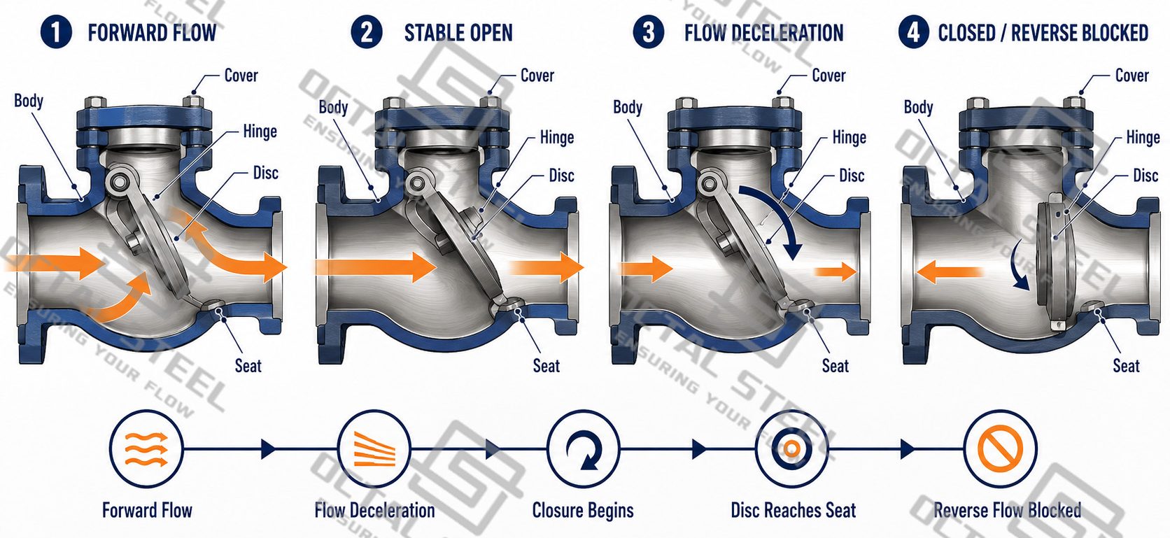
A well-selected valve starts closing early enough that the closure element has limited travel remaining when the flow reaches zero. If the disc remains far from the seat while the fluid is already reversing, the reverse flow can accelerate both the fluid column and the disc before the valve shuts. The sudden arrest of that moving fluid can contribute to a pressure transient commonly associated with valve slam or water hammer.
This relationship explains why two check valves with the same nominal size and pressure class can behave very differently in the same pipeline. Disc mass, hinge location, spring force, closure travel, flow velocity and system deceleration all affect the closing event.
Main Components of a Steel Check Valve
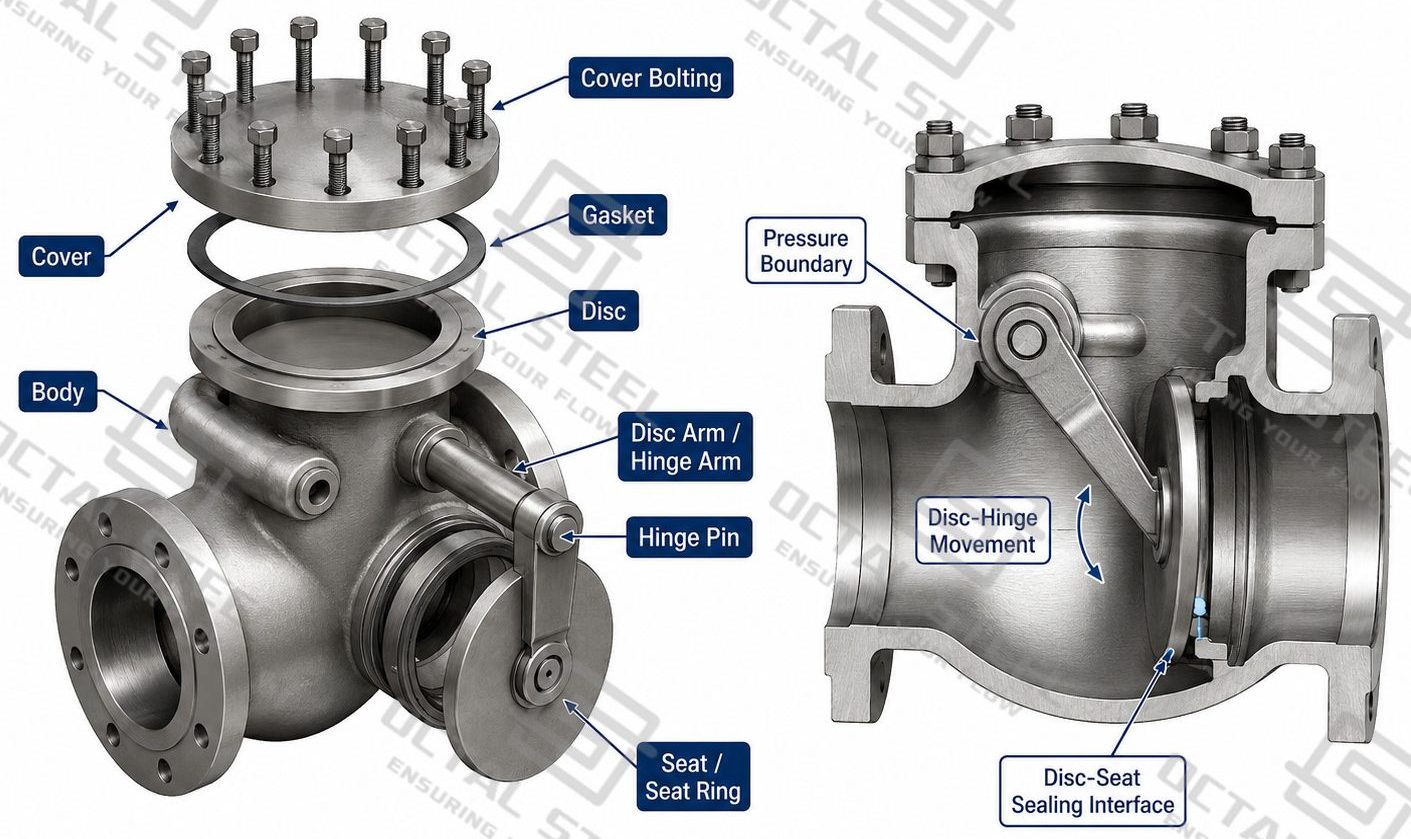
The exact construction changes with valve type, but an industrial steel check valve normally contains several functional groups.
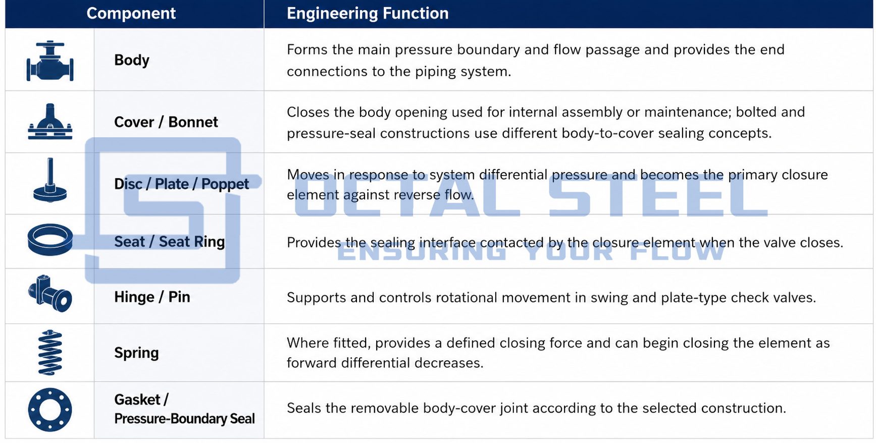
A swing valve does not need the same internal mechanism as an axial or lift design. The closure mechanism therefore has to be evaluated together with the body rather than treating every check valve as the same product with a different external shape.
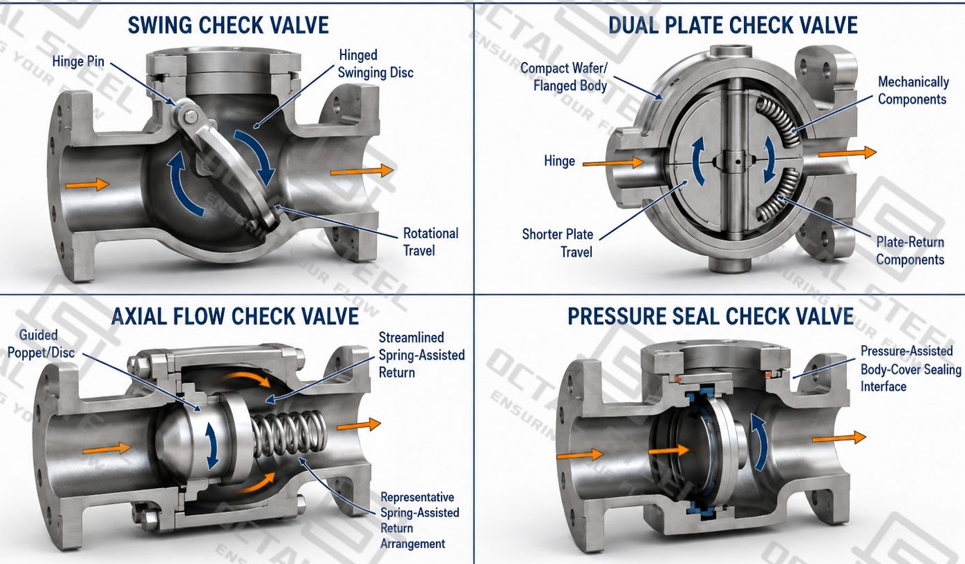
Industrial Check Valve Types and Engineering Differences
Swing Check Valve
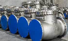
Swing check valve is the most important subtype for this page from both an industrial product and search-demand perspective. It uses a disc connected to a hinge. Forward flow rotates the disc away from the seat; when flow decreases, gravity and the changing pressure differential return it toward the closed position. This basic hinged-disc arrangement is also the main construction shown in the supplied industrial valve references.
When fully open, a properly selected swing design can provide a relatively open flow path and therefore comparatively low flow resistance. This makes it attractive in larger liquid lines where continuous pressure loss matters. Williams likewise highlights the low-pressure-drop advantage of fully open swing designs while warning that an unstable disc can chatter in unsuitable pulsating service.
The same large disc and comparatively long rotational travel that provide an open flow path also matter during shutdown. In systems with rapid flow deceleration, a conventional swing disc may have substantial travel left before it reaches the seat. Swing valves should therefore be evaluated against pump trip behavior, expected velocity and installation orientation instead of being selected only because the line requires backflow protection.
Dual Plate Check Valve and Wafer Check Valve
A dual plate check valve divides the closure element into two semicircular plates mounted around a central hinge. Forward differential rotates the plates into the open position, while springs commonly assist the return movement as the differential decreases. Compared with a large single swing disc, each plate has less mass and a shorter rotational path.
This arrangement is especially useful when piping space and closing response are important. The supplied product range includes dual plate configurations from DN50 to DN1200 / NPS 2–48, with flanged or wafer installation and a reference range of PN10–PN100 / Class 150–600.
A wafer check valve describes the compact body arrangement installed between mating pipeline flanges; it does not define only one internal closure mechanism. The supplied reference material shows wafer check configurations using dual plate swing, single plate and lift-type arrangements. This distinction is important when specifying a valve because two valves described as “wafer check valves” can have different opening forces, internal travel and dynamic closing behavior.
Axial Flow Check Valve
An axial flow check valve uses a guided closure element that travels generally along the pipeline axis rather than rotating through the long arc of a conventional swing disc. The flow passage is shaped around the guided element, and many industrial axial designs use spring assistance so that closure can begin as forward differential falls.
The engineering value of the axial arrangement is not simply “faster closing.” The shorter guided movement can reduce the remaining closure travel as flow approaches zero, which can be advantageous in systems where rapid deceleration and reverse velocity are major concerns. The actual transient response still depends on valve sizing and the system itself, so an axial valve should not be described as automatically eliminating water hammer.
The supplied reference range covers DN50–DN1200, PN10–PN250 / Class 150–1500, with flanged or butt-welded connections.
Pressure Seal Check Valve
A pressure seal check valve needs to be understood differently from swing, dual plate or axial types. “Pressure seal” primarily describes the body-to-cover or bonnet sealing construction rather than the fundamental check-valve closure motion.
In a pressure-seal arrangement, internal pressure acts on the sealing system so that the body-cover joint develops pressure-assisted sealing. This construction is associated with services where pressure and temperature place greater demands on the bonnet joint, but its suitability still depends on the selected material, pressure class and project standard.
The supplied pressure-seal check valve reference covers DN50–DN600 / NPS 2–24 and PN10–PN420 / Class 150–2500 with flanged or butt-welded ends.
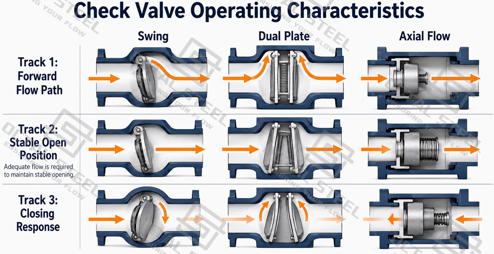
Check Valve Operating Characteristics
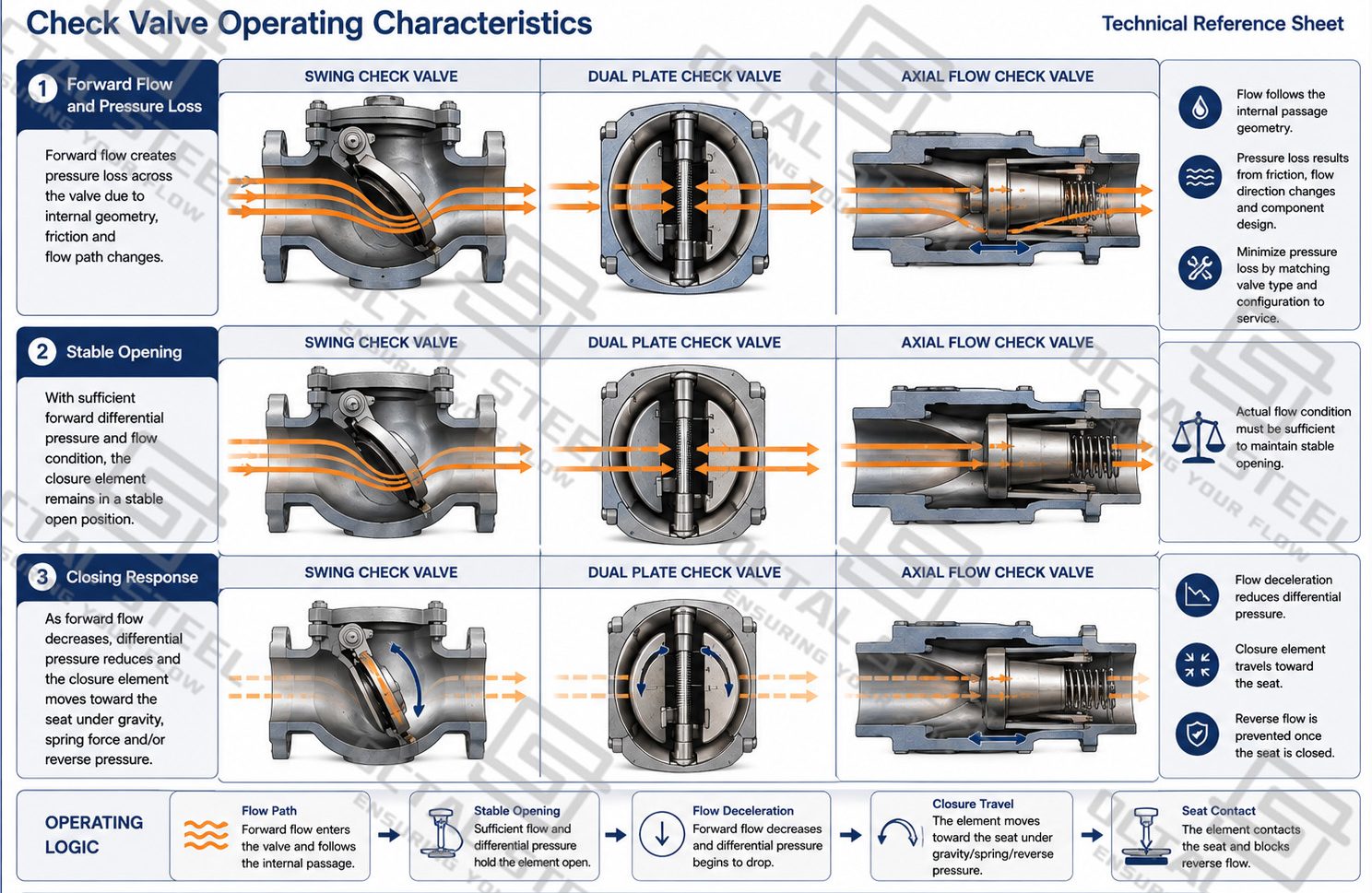
The operating performance of a check valve depends on how the closure element interacts with the flowing medium. Valve type, internal flow path, disc or plate movement and closing force all influence pressure loss during forward flow and the way the valve responds when flow stops or reverses.
- Pressure Loss During Forward Flow
When the valve is open, the medium still has to pass around the disc, plates or guided closure element. This creates a certain pressure loss across the valve. A swing check valve moves its disc away from the seat through a hinged motion, while dual plate and axial-flow designs use different internal flow paths and closure arrangements. The resulting flow resistance therefore varies by design and operating position.
Pressure drop becomes particularly important in continuously operating pump and process lines because unnecessary resistance increases the energy required to maintain the required flow.
- Stable Opening at Normal Flow
A check valve should remain in a stable open position during normal operation. The flowing medium must generate sufficient force to keep the disc, plates or guided element away from the seat.
If the actual flow is much lower than the condition for which the valve was selected, the closure element may remain only partially open or move repeatedly with changing flow. This can increase wear on the seat, hinge, guide or spring and may shorten the service life of the internal components.
For this reason, nominal pipe size alone is not enough to determine whether a check valve will operate properly.
- Closing Response When Flow Stops
When forward flow decreases, the closure element begins moving back toward the seat. The distance it must travel and the force that drives the closing movement depend on the valve design.
A swing check valve uses a hinged disc with a comparatively long rotational movement. A dual plate check valve divides the closure element into two smaller plates and normally uses a shorter closing travel. An axial flow check valve uses a guided element moving along the flow axis and may incorporate spring assistance.
These structural differences affect how quickly the valve approaches the seat as flow decreases. The appropriate configuration should therefore be selected according to the normal flow condition, acceptable pressure loss, shutdown behavior and required closing response of the piping system.
Download:Check Valve Working Principle Construction and Operating Behavior.pdf
Check Valve Materials and Trim Selection
The supplied industrial range uses carbon steel, alloy steel and stainless steel as main body-material routes. Material selection should separate the pressure boundary from the internal parts that actually move, contact the seat and remain exposed to flowing media.
Body and cover selection is driven mainly by design pressure and temperature, media compatibility and the applicable pressure-temperature rating system.
Disc, plate and seat surfaces require separate attention because they experience contact stress during closing and may also face erosion, corrosion or repeated impact. A suitable body material does not automatically mean that the same material is the best trim choice.
Hinge pins, guides and springs, where used, are moving or loaded components. Their compatibility with the process medium and the expected cycling condition is important to reliable closure.
A stainless steel check valve may be selected when corrosion resistance is a major requirement, but grade selection still has to follow the actual process medium and temperature. Carbon or alloy steel routes may be more appropriate for other pressure-temperature and process conditions. Material names should therefore be specified together with valve type, trim and service condition rather than used as a standalone purchasing description.
API 594 Check Valve and Applicable Standards
For industrial procurement, the standard attached to the valve should identify what aspect of the product it actually controls.
| Standard | Main Relevance to Industrial Check Valves |
|---|---|
| API 594 | Covers check valves with flanged, lug, wafer and butt-welding configurations and is a key industrial check-valve product standard. |
| API 602 | Applies to compact gate, globe and check valves through DN100 / NPS 4 in its defined petroleum and natural-gas-industry scope. |
| ASME B16.34 | Covers pressure-temperature ratings, materials, dimensions/tolerances, NDE requirements, testing and marking for applicable valve construction. |
| ASME B16.10 | Controls applicable face-to-face and end-to-end dimensions to support installation interchangeability. |
| ASME B16.25 | Controls preparation of butt-welding ends for components joined into a piping system. |
| API 598 | Provides inspection, examination and pressure-testing requirements for valve types including check valves. |
| BS 1868 | May be specified for applicable steel check valve projects; it is also identified in the supplied cast-steel valve reference. |
API identifies API 594 specifically for flanged, lug, wafer and butt-welding check valves, while API 602 covers gate, globe and check valves in sizes DN100 / NPS 4 and smaller within its scope. ASME currently describes B16.34 as covering pressure-temperature ratings, materials, dimensions, tolerances, NDE, testing and marking for applicable valve construction. B16.10 addresses face-to-face and end-to-end dimensions, while B16.25 addresses butt-welding-end preparation.
A procurement specification should not assume that every forged steel check valve is automatically API 602 or that every wafer design automatically satisfies API 594. The applicable standard has to match the actual construction, size, pressure class and ordered configuration.
How to Select an Industrial Check Valve
Selection should start from what happens in the pipeline before choosing the physical valve type.
This sequence often changes the valve choice. A large swing check valve may be attractive for a continuous-flow line with strict pressure-loss limits. A compact dual plate or axial-flow arrangement may be more appropriate where closing response and installation space dominate. Pressure-seal construction becomes relevant when the body-cover sealing system must meet a more demanding pressure-temperature duty.
Manufacturing, Inspection and Pressure Testing
Check valve manufacturing has to control both the pressure boundary and the moving closure mechanism.
The process starts with material identification and verification of cast or forged pressure-boundary components. Body, cover, seats, hinge or guide interfaces and connection surfaces are then machined to the required geometry. Disc-to-seat contact, hinge alignment and guided-element movement require particular attention because dimensional error in these areas can affect both sealing and dynamic operation.
After assembly, inspection should verify the required dimensions, end connections, closure movement, marking and material traceability. Nondestructive examination is applied where required by the governing standard or project specification. Shell and seat pressure testing is then performed according to the applicable valve standard and approved inspection plan rather than using one invented test pressure or holding time for every configuration. ASME B16.34 includes applicable NDE, testing and marking requirements, while API 598 addresses valve inspection and pressure testing.
For project release, the documentation package should maintain the relationship between the ordered valve, material identification, inspection records, test results and final marking.
Download:Check Valve Working Principle Construction and Operating Behavior.pdf
Industrial Check Valve Applications
Pump Discharge Lines
When a process or transfer pump stops, the downstream fluid column can attempt to reverse toward the pump. A correctly selected check valve closes the discharge line before reverse flow can produce unacceptable pump reverse rotation or system disturbance. Pump shutdown behavior and flow deceleration are therefore as important as the normal operating flow rate. Industrial manufacturer guidance identifies pump discharge protection as one of the principal check-valve duties.
Compressor and Gas Systems
At compressor discharge, the valve prevents downstream pressure from driving gas back through a stopped compressor. The low density and compressibility of gas make stable closure and response to pulsation important; the valve should be evaluated for the actual compressor operating profile rather than selected only from line size.
Steam and Boiler Feedwater Systems
In feedwater or steam service, a check valve prevents high-pressure downstream fluid from returning toward the pump or upstream equipment after loss of forward flow. Material selection, pressure-temperature rating and closing behavior become especially important where thermal conditions and rapid equipment trips occur.
Refinery and Chemical Transfer Piping
Check valves can separate process sections when pressure conditions change unexpectedly, preventing a higher-pressure downstream section from forcing media backward into a transfer pump or upstream process line. For corrosive media, body material, trim and seat materials have to be reviewed together rather than specifying only a stainless steel body.
OCTAL STEEL Check Valve Supply and Project Support
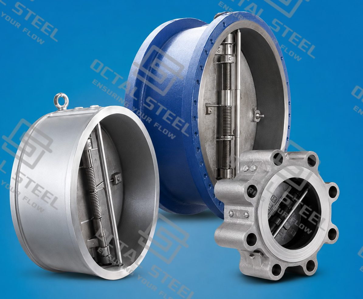
OCTAL STEEL supplies industrial steel check valves in swing, dual plate, axial flow and pressure-seal configurations using carbon steel, alloy steel and stainless steel material routes. Available connection concepts include flanged, butt-welded, wafer, threaded and socket-welded ends depending on valve type and size.
For project selection, the RFQ should identify the valve type, nominal size, pressure designation, design standard, body and trim materials, end connection, process medium, design and operating pressure/temperature, installation orientation, inspection requirements and required documentation. These inputs allow the check valve manufacturer and project engineering team to evaluate the actual flow duty instead of releasing a valve based only on nominal size and pressure class.
FAQ
Q: Can a check valve be selected only by matching the pipeline size?
A: No. Line size establishes the connection, but stable operation also depends on normal flow velocity, pressure drop, valve geometry and closure dynamics. An oversized valve can operate with an unstable disc or plate even when its pressure rating is correct.
Q: Is a dual plate check valve the same as a double check valve?
A: No. A dual plate check valve uses two plates within one valve body. “Double check valve” commonly refers to two check elements arranged in series for backflow protection and should not be used as a synonym for dual plate construction.
Q: Does an API 594 check valve automatically cover every check valve configuration?
A: No. API 594 has a defined scope for applicable flanged, lug, wafer and butt-welding check valves. The ordered design, size, pressure designation and construction still have to be checked against the standard scope and project specification.
Q: What information should be included when requesting a steel check valve quotation?
A: Specify valve type, size, pressure designation, standard, body and trim materials, end connection, process medium, pressure/temperature conditions, installation orientation, inspection requirements and documentation requirements.