Your Responsible Supplier Partner for Oil and Gas Products.
LNG Tank
Recent Products


Rencent Articles


LNG Tank
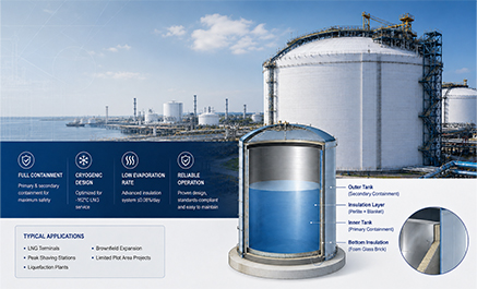
Full containment LNG tank with primary and secondary containers for liquid and vapor safety.
Designed for -162°C LNG storage under API 620 / API 625 project requirements.
≤0.08%/day evaporation rate with foam glass, perlite, and roof insulation system.
BOG recovery, flare/vent route, pressure control, and vacuum protection included in system design.
Clear package scope: tank body, insulation, pumps, piping, instruments, fire protection, testing, and documents.
An LNG tank, also called an LNG storage tank, is a cryogenic containment system designed to store liquefied natural gas at approximately −162°C while controlling heat ingress, boil-off gas, liquid containment, and external environmental loads. Depending on project capacity, site conditions, safety philosophy, and applicable design standards, the tank may use single, double, or full-containment construction. It is commonly selected for LNG peak-shaving stations, liquefaction plants, receiving terminals, industrial fuel-storage sites, and brownfield expansion projects where secondary containment, vapor-tight protection, plot space, safety distance, and interface control are critical.
Octal Steel supplies LNG full containment storage tank packages based on project design conditions, including tank body, insulation system, thermal corner protection, process piping, submerged pump system, instrumentation, fire protection interface, electrical connection, grounding interface, site installation, testing, and commissioning support.
For EPC contractors and project owners, the key issue is not only tank capacity. A reliable LNG tank package must define the containment type, design code, operating pressure, insulation route, BOG handling, pressure protection logic, instrument redundancy, battery limit, and final handover documents before quotation.
Table 1:LNG Storage Tank Containment Type Comparison
| Tank Type | Liquid Containment | Vapor Containment | Bund Requirement | Typical Project Fit |
|---|---|---|---|---|
| Single Containment LNG Tank | Inner tank only | Primary tank / roof space | External bund normally required | Open-area LNG storage with lower plot restriction |
| Double Containment LNG Tank | Primary tank and secondary liquid container | Secondary container may not fully retain vapor | Reduced bund requirement, subject to project design | Projects requiring higher safety than single containment |
| Full Containment LNG Tank | Primary container and secondary container | Secondary container maintains vapor-tight protection | Large external bund can often be reduced | LNG terminals, peak shaving stations, brownfield expansion, limited plot area |
| Membrane LNG Tank | Membrane system with supporting structure | Integrated tank system | Defined by tank concept and local code | Large LNG terminal projects with specific technology requirements |
LNG Storage Tank Containment Types
The containment concept is one of the first decisions in LNG storage tank design because it determines how the primary liquid container, secondary containment, insulation system, roof, and outer structure perform during normal operation and a potential leakage event. LNG storage tanks are selected according to the required containment philosophy, site layout, safety distance, available plot area, and project budget. A single containment tank may be suitable for smaller or open-area projects where a separate bund is provided, while a full containment tank is generally preferred where higher safety requirements, tighter site constraints, or integrated secondary containment are required.
A full containment LNG tank includes a primary container and a secondary container. The primary container stores LNG under normal operation. The secondary container is designed to retain the liquid product in case of primary container leakage and maintain vapor-tight containment. Compared with a single containment tank, this structure reduces reliance on a large external bund and is more suitable for LNG facilities with stricter safety and land-use requirements.
Octal Steel helps buyers compare single containment, double containment, and full containment options during the early technical stage, so the selected tank structure can match the project layout, fire protection philosophy, and local approval requirements.
When to Choose a Full Containment LNG Tank
API 620 LNG Storage Tank Design Basis
LNG full containment storage tanks are normally designed as site-erected, vertical, flat-bottom, low-pressure cryogenic storage systems. The project design basis may include API 620, API 625, EN 14620, GB/T 26978, SY/T 0608, and related local fire, electrical, welding, NDT, and insulation standards.
API 620 is commonly used for large welded low-pressure storage tanks, while API 625 covers refrigerated liquefied gas storage tank systems. For LNG projects, these standards are normally combined with material standards, welding procedure requirements, non-destructive testing requirements, fire protection codes, electrical classification, and local approval rules.
Octal Steel prepares the tank proposal according to the project data sheet, including capacity, design temperature, operating pressure, material selection, seismic load, wind load, insulation system, pump configuration, and required inspection documents.
Table 2: Typical Design Standards
| Category | Common Standards / Codes | What They Control |
|---|---|---|
| Tank Design | API 620, API 625, EN 14620, GB/T 26978, SY/T 0608 | Low-pressure cryogenic tank design, containment concept, and tank system requirements |
| Material | Project data sheet, GB/T 24511, GB/T 3274, or equivalent project-approved material standards | Stainless steel plate, carbon steel plate, and low-temperature material selection |
| Welding | WPS/PQR, NB/T 47014, or project-approved welding procedure standards | Welding procedure qualification, welder qualification, and welded joint control |
| NDT | NB/T 47013 or project ITP requirements | RT, UT, PT, MT, vacuum box test, and acceptance criteria |
| Insulation | SY/T 7349 or project insulation specification | Foam glass brick, expanded perlite, elastic blanket, insulation installation, and inspection |
| Fire and Electrical | Local fire code, hazardous area classification, and project electrical standard | FGS, dry powder system, fire water interface, explosion-proof instruments, and junction boxes |
Typical 10,000 m³ LNG Full Containment Storage Tank Parameters
The following data is a typical reference for a 10,000 m³ double-wall metal LNG full containment storage tank. Final dimensions, material selection, pressure settings, roof configuration, and instrument list should be confirmed according to the project design basis.
Table 3: Typical 10,000 m³ LNG Full Containment Tank Parameters
| Item | Typical Reference Value | Notes for Buyer Review |
|---|---|---|
| Equipment Name | 10,000 m³ LNG Storage Tank | Final capacity can be adjusted by project design basis |
| Tank Type | Double-wall metal full containment tank | Primary container and secondary container |
| Design Standard | API 620-2018 | API 625, EN 14620, or GB/T 26978 can be added by project requirement |
| Inner Tank Medium | Liquefied Natural Gas | Stored at cryogenic temperature |
| Design Temperature | -168°C | For cryogenic design margin |
| Working Temperature | Approx. -162°C | Typical LNG operating temperature |
| Effective Volume | 10,000 m³ | Working volume to be confirmed by operating philosophy |
| Design Liquid Level | 21,200 mm | Subject to tank diameter and net capacity |
| Inner Tank Diameter | 25,000 mm | Reference value |
| Outer Tank Diameter | 27,000 mm | Reference value |
| Main Material | S30408 or project-approved equivalent | Final grade depends on code, temperature, and owner specification |
| Bottom Insulation | Foam glass brick | Load-bearing and thermal insulation function |
| Annular Insulation | Expanded perlite and elastic blanket | Controls sidewall heat ingress and perlite pressure |
| Static Evaporation Rate | ≤0.08% per day | Subject to final insulation design and ambient conditions |
In this configuration, LNG is stored in the inner tank. The outer tank retains BOG and insulation material under normal operation and provides secondary containment under leakage conditions. Both the inner and outer tanks are vertical, cylindrical, flat-bottom steel tanks. The inner tank is generally designed as an open-top self-supporting container with a suspended deck, while the outer tank uses a dome roof structure to provide vapor-tight enclosure and roof support.
Double-Wall Metal LNG Full Containment Tank Structure
A typical double-wall LNG full containment tank consists of the following main parts:
Inner tank: The inner tank stores LNG at about -162°C. It is supported on the bottom insulation layer and separated from the outer tank by an annular insulation space. The shell course thickness is designed according to liquid height, hydrostatic load, wind load, seismic load, and code requirements.
Outer tank: The outer tank is a self-supporting sealed steel container with a dome roof. It retains vapor, protects insulation material, and acts as the secondary containment barrier when the primary container leaks. The outer shell and roof structure are designed for pressure stability, vapor tightness, and long-term operation.
Suspended deck: The suspended deck is supported from the outer roof structure and separates the cold internal space from the roof insulation area. It also supports roof insulation and related internal components.
Thermal corner protection: The thermal corner protection system is installed at the bottom annular area between the inner and outer containers. It protects the outer tank bottom corner weld area from direct cryogenic exposure during primary container leakage.
Insulation system: The bottom insulation, annular insulation, and suspended deck insulation work together to reduce heat ingress, control static evaporation rate, and keep the foundation and outer tank structure within safe temperature limits.
Top platforms and access: The tank top is normally arranged with pump wells, process piping, valves, pressure/vacuum relief devices, vent connections, dry powder fire protection equipment, walkways, platforms, and ladders for operation and maintenance.
Thermal Corner Protection for Leakage Condition
Thermal corner protection is a critical detail in an LNG full containment tank. If the inner tank leaks, LNG may enter the annular bottom area. Without proper protection, cryogenic liquid can transfer cold energy directly to the outer tank shell-to-bottom corner weld. This area is sensitive because the weld is exposed to high thermal stress when a local temperature drop occurs.
The thermal corner protection system helps keep leaked LNG away from direct contact with the outer bottom corner area. It reduces the risk of sudden temperature gradient, protects the outer tank bottom weld zone, and supports the containment function during abnormal conditions.
For buyers, thermal corner protection should not be treated as a simple accessory. It should be reviewed together with the inner tank bottom, outer tank bottom, annular insulation, foam glass brick layout, perlite concrete ring beam, welding details, and leakage-condition design basis.
LNG Storage Tank Insulation System and Boil-Off Control
The LNG storage tank insulation system affects tank heat ingress, BOG generation, static evaporation rate, and foundation temperature control. For LNG storage, insulation is not only a thermal issue. It also affects structural load transfer, bottom settlement behavior, annular space stability, and commissioning quality.
LNG storage tank insulation cannot be selected from thermal conductivity alone. The review must also consider compressive strength, settlement, moisture resistance, thermal contraction, installation density, joint continuity, long-term aging, and compatibility with the inner and outer containment structures.
Table 4: LNG Tank Insulation System
| Tank Area | Typical Insulation Route | Function | Buyer Check Point |
|---|---|---|---|
| Bottom Insulation | High-strength foam glass brick and perlite concrete ring beam | Supports inner tank load and reduces downward heat ingress | Compressive strength, leveling layer, load distribution, and installation tolerance |
| Annular Wall Insulation | Expanded perlite and elastic blanket | Reduces sidewall heat ingress and buffers perlite pressure | Perlite filling density, settlement allowance, and elastic layer continuity |
| Suspended Deck / Roof Area | Glass fiber insulation or project-approved roof insulation system | Reduces heat ingress from roof space and controls BOG generation | Layer thickness, material grade, installation record, and moisture protection |
| Thermal Corner Area | Thermal corner protection and bottom insulation transition | Protects outer tank bottom corner weld from cryogenic exposure during leakage condition | Protection layout, weld zone protection, and leakage-condition design review |
Bottom insulation normally combines high-strength foam glass brick and perlite concrete ring beam. The inner tank shell area has concentrated load, so the insulation material must provide both compressive resistance and low thermal conductivity. Leveling layers are used to improve load distribution and reduce local stress concentration.
Annular sidewall insulation usually uses expanded perlite with an elastic blanket around the inner shell. The elastic blanket buffers lateral pressure from perlite and reduces direct load concentration on the inner tank shell. Proper perlite filling density is important for long-term insulation performance.
Suspended deck insulation reduces heat ingress from the roof area. The final layer thickness, material grade, and installation method should be confirmed according to the thermal calculation and project evaporation-rate requirement.
For a typical 10,000 m³ LNG full containment tank, the static evaporation rate can be designed to a controlled level, such as ≤0.08% per day, subject to final tank size, insulation design, ambient condition, and operating mode.
Filling, Pre-Cooling and Withdrawal Process
The LNG filling system can be arranged with both top filling and bottom filling lines. A typical design may use DN250 top and bottom filling lines, each with independent remote control valves. By switching or adjusting top and bottom filling, operators can reduce temperature stratification and improve tank operating stability.
Before full LNG receiving, the tank requires controlled pre-cooling. A spray-type pre-cooling line can be arranged below the suspended deck, with isolation valves at the line root. The line is positioned to distribute cryogenic liquid evenly into the tank and reduce local cold shock during commissioning.
For withdrawal, LNG is normally discharged through submerged pumps. A common configuration uses two submerged pumps, one duty and one standby. Each pump column outlet can be arranged with check valve and root valve. The discharge line may include a flowmeter, emergency shutdown valve, and return control line. The return line helps maintain the pump minimum continuous flow and can also mix tank liquid to reduce LNG stratification.
This process arrangement is especially important for peak shaving stations and truck loading terminals, where receiving, storage, recirculation, and withdrawal conditions may change frequently.
BOG Recovery and Pressure Protection System
BOG is generated by normal heat ingress, filling operation, pressure fluctuation, and liquid movement. A full containment LNG tank should include a BOG recovery line, pressure control line, flare or vent interface, and safety relief devices.
The tank pressure is normally controlled through BOG recovery first. If pressure rises beyond the normal operating range, the system can increase BOG compressor load, open a flare control valve, open vent shutdown valves, or activate breathing valves according to the pressure set points. Negative pressure protection is also required to prevent vacuum damage to the tank structure.
Table 5: Typical Pressure Protection Logic
| Tank Pressure Condition | Typical Control Action | Purpose |
|---|---|---|
| Normal operating range | Maintain tank pressure around 12–15 kPa through BOG recovery | Keep stable vapor space pressure and reduce unnecessary venting |
| Pressure > 15 kPa | BOG compressor increases recovery load | Recover more boil-off gas before venting or flaring |
| Pressure > 17 kPa | Flare control valve opens | Send excess BOG to flare system |
| Pressure > 18 kPa | Vent shutdown valve opens | Provide additional pressure relief path |
| Pressure > 19 kPa | Breathing valve opens | Protect tank from overpressure |
| Pressure < 12 kPa | BOG compressor reduces recovery load | Prevent pressure from dropping too fast |
| Pressure < 5 kPa | Nitrogen or natural gas make-up valve opens | Restore vapor space pressure |
| Pressure < -0.3 kPa | Vacuum breaker opens | Protect tank shell and roof from vacuum damage |
This pressure protection table should be confirmed against the project P&ID, SIL/LOPA analysis, local code, and owner operating philosophy. Octal Steel can coordinate the tank-side piping, valves, instruments, and signal interface according to the agreed battery limit.
LNG Storage Tank Gauging, SIS and Instrumentation
LNG tank instrumentation should provide reliable measurement under low-temperature conditions and support both process control and safety interlock. A typical tank gauging system may include two servo level gauges and one radar level gauge. This gives measurement redundancy through different measurement principles.
The level gauges can provide 4–20 mA signals to the SIS and DCS. High-level and low-level switch signals are used for interlock protection, including overflow prevention and pump protection under low liquid level.
The temperature measurement system may include one average temperature device and multiple surface temperature points on the tank wall and bottom. Surface RTDs mounted in stainless steel protection tubes can monitor temperature distribution during pre-cooling, commissioning, and normal operation. Temperature signals can be transmitted to DCS through multi-point transmitters.
Pressure measurement is normally arranged with multiple pressure transmitters and voting logic. For example, 2oo3 pressure voting can improve reliability for pressure alarm and safety interlock. Field instruments should be selected according to hazardous area classification, ingress protection requirement, SIL requirement, and owner-approved vendor list.
Fire, Gas Detection and Safety Package
The fire and gas safety package for an LNG full containment tank may include flame detection, combustible gas detection, low-temperature leakage detection, dry powder extinguishing system, fire water spray or water mist cooling system, emergency shutdown interface, and local alarm signals.
At the tank top, flame detection and temperature detection can be arranged near the vent area. When flame and high temperature are detected at the same time, the fire and gas system can trigger dry powder extinguishing. The dry powder system should include automatic, manual, and mechanical emergency start modes.
For tank shell cooling, the fire water system may use spray or water mist depending on project fire protection philosophy. The interface should be clearly divided between tank supplier and owner/EPC contractor, especially for water supply, fire approval, control signal, and installation boundary.
LNG Storage Tank Supply Scope and Battery Limit
A clear supply scope reduces quotation mistakes and construction disputes. LNG full containment tank procurement should not only list the tank shell and bottom plates. The buyer should confirm whether the package includes insulation material, submerged pumps, pump wells, process piping, valves, instruments, fire protection, electrical cables, grounding points, installation, testing, commissioning, and handover documents.
Table 6: Typical Supply Scope and Battery Limit
| Scope Item | Typical Included Content | Battery Limit / Clarification Point |
|---|---|---|
| Tank Body | Inner tank, outer tank, bottom plates, shell plates, roof structure, and suspended deck | Foundation interface and anchor/embedment responsibility to be confirmed |
| Thermal Protection | Thermal corner protection, bottom insulation, annular insulation, and roof insulation | Insulation material brand, installation method, and evaporation-rate requirement |
| Process Piping | Filling line, withdrawal line, return line, BOG line, purge line, drain and vent connection | Boundary at tank bottom pipe rack or first elbow to be confirmed |
| Pump System | Submerged LNG pumps, pump wells, check valves, root valves, and related tank-side piping | Pump brand, flow rate, head, and duty/standby philosophy |
| Valves | Manual valves, pneumatic shutdown valves, control valves, relief valves, and vacuum protection valves | Fire-safe requirement, fail-safe position, actuator, and solenoid specification |
| Instrumentation | Level gauges, temperature instruments, pressure transmitters, local indicators, and signal cables within scope | DCS/SIS/ESD/FGS signal interface and junction box boundary |
| Fire Protection | Tank-top dry powder system, fire/gas detection interface, and tank shell/roof spray piping within tank scope | Fire water supply, approval, and site-wide fire system responsibility |
| Electrical | Explosion-proof junction boxes, tank-side cable trays, and local power/control connection within scope | Power supply and control cabinet boundary to be confirmed |
| Grounding | Static grounding lugs and tank-side grounding connection points | Connection to underground grounding grid normally by owner or EPC |
| Installation and Testing | Site erection, welding, NDT, pressure test, pneumatic test, airtightness test, vacuum test, and commissioning support | Site utilities, lifting access, temporary power, water, and permits to be confirmed |
| Documentation | MTC, WPS/PQR, welder qualification, NDT reports, test records, calibration records, and handover dossier | Final MDR / handover dossier format should be agreed before order release |
Octal Steel can support either a tank-body supply scope or an integrated tank package scope, depending on project requirements. For brownfield projects, the battery limit should be confirmed earlier than price negotiation because existing pipe racks, cable routes, fire water system, DCS/SIS cabinet, grounding grid, civil foundation, and site access may affect both cost and schedule.
Construction and Quality Control
LNG tank construction should be controlled through approved material procedures, foundation acceptance, plate prefabrication, welding qualifications, dimensional surveys, insulation installation records, nondestructive examination, hydrostatic and pneumatic testing, airtightness or vacuum testing, settlement monitoring, final cleaning, and turnover documentation.
The main construction sequence usually includes foundation acceptance, outer tank bottom installation, outer shell erection, roof compression ring installation, dome roof structure installation, suspended deck assembly, thermal corner protection, bottom insulation installation, inner tank bottom and shell erection, process nozzle installation, pump well installation, perlite filling, tank pressure test, pneumatic test, airtightness test, vacuum test, cleaning, instrument calibration, and handover.
Inspection records should be linked with material heat number, welding map, WPS/PQR, welder qualification, NDT report, pressure test record, insulation installation record, instrument calibration record, and final handover dossier. For project owners, this document chain is as important as the tank itself because it supports site acceptance and future operation traceability.
Project Failure Map: What Buyers Should Control Before Ordering
A full containment LNG tank is not a catalog product, and most procurement problems begin before manufacturing starts. When comparing LNG tank manufacturers, buyers should look beyond nominal capacity and price and confirm the containment concept, governing standards, design responsibilities, insulation scope, foundation interface, field-joint responsibilities, inspection plan, commissioning support, and final document package during technical clarification.
Containment mismatch: If the owner requires full containment but the quotation only covers a single containment or double containment concept, the project may fail during design review. The containment type, leakage condition, vapor containment, and bund philosophy must be confirmed in writing.
Insulation performance gap: If the insulation material, installation density, bottom load-bearing route, and static evaporation rate are not aligned, BOG volume may be higher than expected. The buyer should request insulation design basis, material list, and installation method.
BOG and pressure logic mismatch: If the BOG recovery, flare, vent, breathing valve, and vacuum protection set points are not coordinated, the tank may need rework during P&ID review. Pressure control philosophy should be reviewed together with DCS/SIS and ESD logic.
Battery limit dispute: If the quotation does not define piping, valves, fire protection, electrical, grounding, civil interface, and instrument signals, cost may move between supplier, EPC, and owner during construction. Battery limit drawings and scope tables should be part of the commercial offer.
Document gap: If MTC, WPS/PQR, NDT report, pressure test report, calibration records, and commissioning documents are not included, the owner may face acceptance delay. Octal Steel recommends confirming the final documentation list before order release.
Why Choose Octal Steel for LNG Full Containment Storage Tank Projects
Octal Steel supports LNG storage tank projects by coordinating tank materials, containment interfaces, insulation requirements, fabrication records, inspection stages, and project documentation from early technical clarification through final delivery. Before the formal offer, we help confirm the tank type, capacity, design code, design temperature, pressure range, insulation system, BOG route, pump configuration, instrument interfaces, and supply boundaries.
For EPC contractors, this reduces repeated clarification between process, mechanical, civil, electrical, instrumentation, and fire-protection teams. For project owners, it makes quotations easier to compare and the supply scope easier to audit.
Project support can include English technical datasheets, material selection, preliminary scope tables, inspection plans, document lists, packing and shipping coordination, third-party inspection coordination, and site installation support according to contract requirements.
Ordering Information Required for Quotation
To prepare a reliable quotation for an LNG full containment storage tank, please provide the following information:
Tank capacity and working volume
Design code and local approval requirement
LNG composition and operating mode
Design temperature and operating temperature
Design pressure and normal operating pressure
Static evaporation rate requirement
Site wind load, seismic load, and ambient condition
Containment type requirement
Material preference for inner and outer tank
Pump flow rate, head, and standby philosophy
BOG recovery and flare/vent interface
Filling, withdrawal, return, purge, and drain requirements
DCS/SIS/ESD/FGS interface requirement
Firefighting and grounding battery limit
Civil foundation responsibility
Inspection, testing, and documentation requirement
Required delivery term and project schedule
FAQ
Q1: What is an LNG full containment storage tank?
A1: It is a cryogenic LNG tank with a primary container and a secondary container. The secondary container can retain leaked LNG and maintain vapor-tight protection.
Q2: When should a full containment LNG tank be selected?
A2: It is suitable for LNG terminals, peak shaving stations, liquefaction plants, and brownfield expansion projects where safety distance and plot area are limited.
Q3: What standards are commonly used for LNG full containment tanks?
A3: Common standards include API 620, API 625, EN 14620, GB/T 26978, welding standards, NDT standards, and local fire protection codes.
Q4: How is BOG controlled in an LNG storage tank?
A4: BOG is controlled by insulation design, BOG recovery, pressure control valves, flare or vent lines, and pressure/vacuum protection devices.
Social Share