Steel pipe piles are structural steel tubular members installed by driving, vibro-hammering, or drilling to form a deep foundation that carries axial compression/tension and lateral loads from the superstructure into competent soil or rock. They are a proven foundation solution for heavy civil, marine, and industrial structures worldwide.Manufactured to ASTM A252 Grade 2 & 3, EN 10219 S355, API 2B, and project-specific requirements.
Octal Steel supplies spiral (SSAW), longitudinal (LSAW), and seamless pipe piles in diameters from 219 mm (8-5/8″) to 3048 mm (120″), wall thickness up to 50 mm, and lengths up to 100 m via spliced sections.In most projects, the steel pipe pile specification is locked by three items first: OD/WT, the governing standard/grade, and the inspection package required for acceptance—then details like splicing plans and coatings are finalized around them.
Standards & Specifications
These steel pipe pile standards set the baseline for grade selection, tolerances, and certification level—so the chemistry and mechanical requirements can be checked against one clear reference.
Standard
Key Grades
Typical Applications
ASTM A252
Grade 1, Grade 2, Grade 3
North America – universal piling, wharves, bridges, ports
EN 10219 / EN 10210
S355J2H, S420MH, S460MH
Europe – bridge piers, offshore wind, heavy marine structures
Australia & New Zealand – high-rise, port & seismic piling
JIS A 5525
SKK400, SKK490
Japan – marine works, earthquake-resistant foundations
All piles can be supplied with EN 10204 3.1 or 3.2 certificates witnessed by Lloyd’s, DNV-GL, ABS, BV, or TÜV when required by the project.
Chemical Composition & Mechanical Properties – Steel Pipe Piles
Standard
Grade
C max %
Si max %
Mn max %
P max %
S max %
CEV max %
Yield Strength min (MPa)
Tensile Strength (MPa)
Elongation min %
CVN (J) at 0 °C
ASTM A252
Grade 2
–
–
–
0.050
–
–
240
415 min
–
–
Grade 3
–
–
–
0.050
–
–
310
455 min
–
27 avg
EN 10219
S355J2H
0.22
0.55
1.60
0.030
0.030
0.45
355
470–630
20
27 avg
S420MH
0.16
0.50
1.70
0.030
0.025
0.46
420
500–660
19
40 avg
S460MH
0.16
0.60
1.70
0.030
0.025
0.47
460
530–720
17
40 avg
JIS A 5525
SKK490
0.23
0.55
1.65
0.030
0.015
0.47
365
490–610
18
47 avg
AS/NZS 1163
C450L0
0.20
0.55
1.70
0.030
0.010
0.45
450
500 min
16
40 avg
OD and wall thickness also drive steel pipe weight per foot, which is often the quickest way to estimate handling, splicing, and freight planning before the full take-off is finalized.
All grades can be supplied with restricted carbon equivalent (CEV ≤ 0.41) and low phosphorus/sulfur for enhanced weld-ability on request.
Charpy V-notch (CVN) requirements can be provided for low-temperature service (for example -20 °C or -40 °C) for offshore wind and cold-region projects.
NACE MR0175 / ISO 15156 compliant options can be supplied for sour environments when specified.
Octal Steel keeps full mill test reports with every heat number — chemistry, tensile, and impact results traceable from raw plate to finished pile.
Core Design Advantages of Steel Pipe Piles
360° Load Distribution & Superior Bending Resistance
A circular pipe pile distributes axial, lateral, and moment loads uniformly, which supports better stability in soft clays and liquefiable sands.
Drivability and penetration
Closed-end or open-end designs with thick walls (up to 50 mm) and factory-fitted driving shoes help penetration through dense sands, gravels, and weak rock with lower refusal risk.
Tension Capacity
Useful for offshore wind and mooring-related structures where uplift resistance is critical.
Minimal Soil Displacement & Low Noise Options
Vibratory or press-in methods can reduce noise and ground disturbance compared to many alternative foundation approaches.
Long-Term Durability in Aggressive Environments
Combined with 3LPE, FBE, or heavy-duty polyurethane coatings plus cathodic protection and sacrificial thickness, design lives of 75–100+ years are routinely achieved in seawater, brackish marshes and contaminated industrial soils.
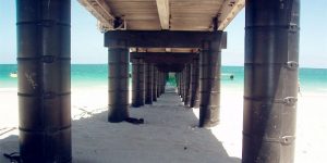
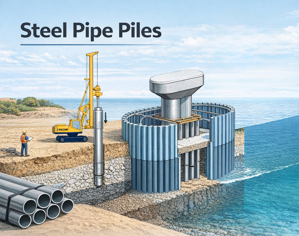
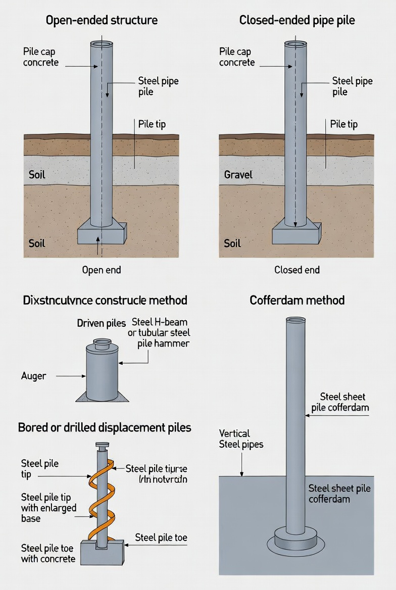
What Image 1 is showing — how projects classify steel pipe pile schemes (procurement-ready view)
Image 1 is not a “driving method” chart. It is a scheme selection map that tells a buyer what must be fixed in the RFQ/PO before installation details are finalized. In practice, the scheme determines pile grouping, cap configuration, temporary works scope, and which documents/QA gates control release.
1) Classification by structure (what you are actually buying as a foundation “system”)
Well type / pipe pile cells
A cellular arrangement of multiple steel pipe piles used as a retaining/containment structure (often waterfront).
Procurement impact: you are not just buying pipe piles—you are buying a cell system that depends on consistent OD/WT, tight length control, and splice repeatability so the cell closes correctly and the cap/closure works on site.
What to lock in the PO (practical fields):
• Pile OD/WT + manufacturing route (SSAW/LSAW/seamless) and straightness/ovality tolerances (so cells align)
• Length strategy (single length vs spliced lengths) + splice detail/weld procedure and NDT scope (UT/RT %)
• Coating/CP interface requirements for permanent marine exposure (shop coating + field repair method)
• Document closure per shipment: heat traceability + NDT records tied to pile IDs (cell projects fail fast when IDs don’t map to paperwork)
Leg-supported type
A pile group supports an elevated pile cap/platform (common for piers, trestles, bridge bents, dolphins).
Procurement impact: the risk is alignment and cap fit, not the pipe itself. If the pile head elevation and pile top geometry wander, the cap work becomes rework.
What to lock in the PO:
• Pile head cut-off allowance + bevel/end prep requirement (for field cut and cap welding)
• Driving shoe requirement (if specified) and toe detail (open vs closed end)
• Splice location control (keep splices out of the cap zone if the drawing requires it)
• Dimensional acceptance package (OD/WT, straightness, end squareness) to match the cap fabrication tolerance stack-up
2) Classification by construction method (how the site creates a workable “dry” or controlled workspace)
Foundation-cum-cofferdam method
The pile group is built together with a cofferdam; the drawing shows cut-off level, bottom concrete (seal), and internal fill to make a controlled dry/low-water workspace.
Procurement impact: this method is driven by temporary works + water control, which changes what the site needs from the piles: coating zones, cut lengths, and release timing are stricter.
What to lock in the PO:
• Coating system with zone definition (submerged / splash / atmospheric) and field repair kit requirement
• Cut-off elevation control: length tolerances + marking reference (datum) so crews can cut to level quickly
• NDT and documentation for splice welds (cofferdam zones often require higher confidence because repair access is hard later)
• Packing/ID logic: bundles must be sequenced so the cofferdam ring/pile group can be installed without re-sorting
Rising method
A staged method where the cap/structure rises as piling and enclosure proceed (useful when the working platform changes with tide/water depth).
Procurement impact: the risk is sequence. Wrong shipment order equals idle crane time.
What to lock in the PO:
• Delivery split by installation sequence (e.g., “Stage 1 ring piles”, “Stage 2 inner piles”, “Stage 3 extensions”)
• Splice strategy aligned to stage heights (predefined splice points, consistent joint prep)
• Clear pile marking durable in wet handling (paint + stamp + tag redundancy)
Cofferdam method (incl. sheet-pile cofferdam)
Pipe piles are installed with a sheet pile cofferdam to form an enclosure for excavation/concreting.
Procurement impact: you are managing two interfaces: pipe pile ↔ sheet pile system and pipe pile ↔ cap/closure concrete. Misalignment or mismatched tolerances shows up as leakage, over-excavation, or rework.
What to lock in the PO:
• Interface tolerances (straightness, OD tolerance, out-of-roundness) because sheet pile cofferdam geometry is unforgiving
• Coating compatibility and field weld repair limits (sheet pile contact zones need predictable coating repair rules)
• Documentation closure: pile ID list that matches the cofferdam layout drawing so QA can release by “ring segment” instead of quarantining the whole lot
Why this belongs before “Common Driving Methods”
From a procurement standpoint, driving method is a downstream choice made by the contractor after reviewing soil, access, noise, and equipment. Image 1 answers the upstream question buyers must solve earlier: what foundation scheme is being built and what procurement controls prevent site rework—OD/WT, lengths/splices, coating zones, sequencing, and traceable QA records.
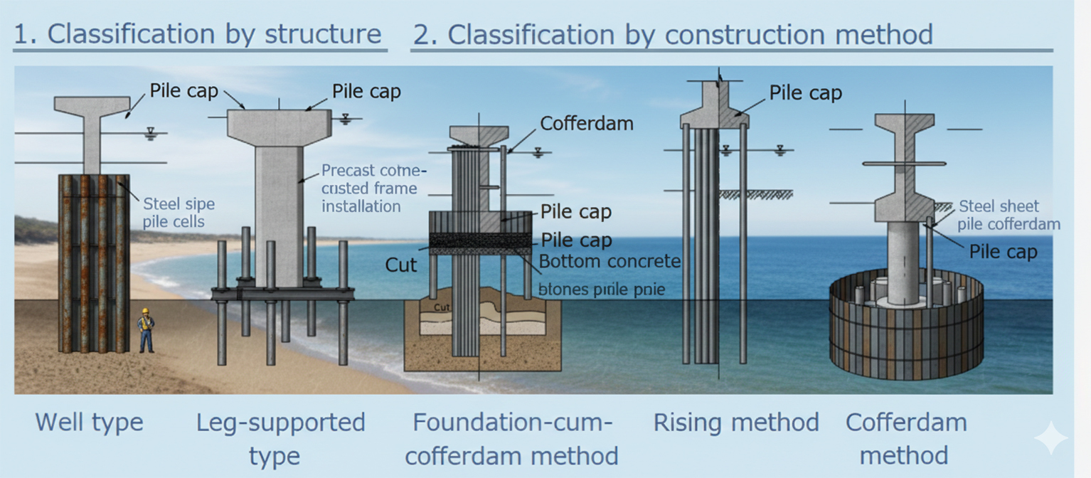
Image 2
What Image 2 is showing — pile end condition + installation families (procurement-ready view)
Image 2 links two decisions that procurement must keep consistent: (1) pile toe configuration (open vs closed) and (2) the installation family (driven vs drilled vs cofferdam-supported works). These are not “nice-to-have descriptions”—they drive shoe/toe accessories, wall thickness risk, welding/NDT scope, and the site acceptance checks that prevent delays after delivery.
1) Pile tip condition (what must be fixed in the pile description)
Open-ended pipe pile (open end)
The pile toe is open, and soil can enter during installation. This configuration is commonly used where drivability and installation speed are priorities, and where the design assumptions allow for soil entering/plugging behavior.
Procurement controls that make this workable on site:
• Confirm whether a driving shoe is required (many open-end piles still use shoes in dense strata or where toe damage risk is high).
• Lock wall thickness and grade so toe deformation risk is controlled under hammer/vibro energy.
• Require durable pile marking + heat traceability because open-end projects often involve more field cutting and splicing—traceability must survive handling.
Closed-ended pipe pile (closed end / with toe plate or shoe)
The toe is closed (by plate or a purpose-built shoe) to control penetration response and reduce uncertainty in certain ground conditions. This is typically specified where toe protection and predictable refusal behavior are part of the installation plan.
Procurement controls that reduce rework:
• Specify the toe closure type explicitly (plate closure vs engineered shoe) and whether it is shop-fitted.
• Align the shoe/plate material spec and weld requirements with the pile spec (WPS/PQR and NDT scope for the toe welds).
• Define the cut-off allowance so the contractor can trim pile heads without compromising required embedment.
2) Installation families (what the site will do, and what procurement must support)
Driven (displacement) piling — impact hammer / vibratory
Installed by hammering or vibration; commonly selected for high production rates where noise/vibration limits and access/headroom allow.
Procurement controls that keep driving production stable:
• Require straightness/ovality control suitable for driving and splicing fit-up (bent/oval piles slow down penetration and splice alignment).
• Lock splice details (location strategy, weld prep, NDT %) to match the contractor’s driving sequence and avoid “field redesign” of joints.
• If coatings are specified, confirm drivability compatibility (coating type, thickness, and field repair method) because driving damage must be repairable and auditable.
Bored or drilled displacement piling — auger/drilling assisted
Uses auger/drilling to advance; commonly used where vibration restrictions, obstructions, or urban constraints limit driven methods.
Procurement controls that prevent mismatch:
• Confirm the installation plan’s tolerance needs (drilled methods can change required length strategy and splice planning).
• Ensure pile end prep supports the planned method (e.g., toe details or shoes may differ from driven piles).
• Documentation must still be heat-traceable—drilled methods often involve staged placement and longer site storage, increasing mix-up risk without clear marking.
Cofferdam method — enclosure-based construction in water
Shows the concept of creating a cofferdam (often sheet piles) so caps/foundations can be built in controlled conditions. Pipe piles may be the primary verticals or part of the system supporting the enclosure and cap.
Procurement controls that matter most:
• Define coating zones (submerged/splash/atmospheric) and field repair acceptance—cofferdam work concentrates corrosion risk at waterline zones.
• Require shipment sequencing and ID mapping to the layout drawing so the enclosure can be assembled without re-sorting piles on barges.
• Keep weld/NDT documentation tied to pile IDs; cofferdam environments are where late QA holds are most expensive because access is constrained.
Why this diagram belongs next to installation content (but before detailed driving method text)
Image 2 is a “decision bridge” between design intent and site execution. It helps buyers write a PO that the contractor can actually install—by locking toe type + installation family + accessory/WPS/NDT + traceability, rather than buying “pipe piles” that later need rework, reclassification, or additional approvals.
Common Driving Methods for Steel Pipe Piles
Steel pipe piles can be installed using multiple proven techniques, selected according to soil conditions, noise restrictions, headroom, and schedule. In practice, steel pipe pile installation is usually decided by soil profile, noise limits, available headroom, and the production rate the schedule can tolerate:
Impact Driving (Diesel or Hydraulic Hammers) The most widely used method worldwide. High energy per blow achieves deep penetration in dense sands, stiff clays and gravel layers. Modern hydraulic hammers offer precise stroke control and low emissions.
Vibratory Driving Ideal for granular soils and medium-dense sands. High-frequency vibration liquefies soil around the pile, allowing rapid sinking with minimal ground disturbance. Frequently used for temporary works and marine projects.
Press-in (Silent/Giken Method) Zero-noise, zero-vibration technique popular in urban and environmentally sensitive areas (Japan, Singapore, central London). The pile is jacked into the ground using reaction force from previously installed piles.
Drilled & Grouted (Rock Socketed Piles) Used when piles must be founded in rock or very hard strata. The pipe is placed in a pre-drilled hole and fully grouted under pressure, developing extremely high end-bearing and skin friction.
Jetting Assistance Water or air jetting from the pile tip is combined with vibration or impact driving to reduce skin friction in clean sands and silts, significantly increasing penetration rates.
Oscillator / Rotator Installation Large-diameter monopiles (offshore wind) are often installed using high-torque rotators or oscillators that twist the pile into the seabed with minimal noise.
Typical Applications
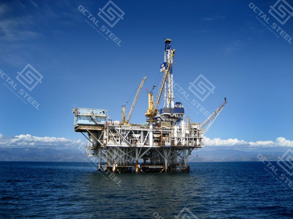
Marine & Port Facilities Wharves, jetties, quay walls, dolphins, and container terminals. Large-diameter spiral or LSAW piles with heavy wall and CWC routinely support 1000+ tonne crane loads in Singapore, Rotterdam, and Dubai ports.
Bridge & Viaduct Foundations Main piers and approach trestles for river, estuary and over-water crossings. High axial + bending capacity replaces multiple smaller concrete piles, proven on Hong Kong–Zhuhai–Macao Bridge and California Bay Area projects. For piling for bridges, this often means fewer piles to install and fewer pile caps to build, which simplifies sequencing on water crossings.
Offshore Wind & Renewable Energy Mono-piles and transition pieces for 8–15 MW turbines. 2000–3000 mm OD, 80–120 mm wall, EN 10219 S355/S420 piles with secondary steel and grouted connections dominate North Sea, Baltic and China offshore wind farms.
High-Rise & Heavy Industrial Structures Deep basements and tower foundations in soft ground. Combined pile-raft systems using 900–2500 mm piles achieve settlements <10 mm under 80+ storey loads in Bangkok, Jakarta and Miami.
LNG & Petrochemical Tank Farms Full-penetration pipe piles resist seismic liquefaction and provide tank settlement control. 100-year design life with corrosion allowance + coating common in Qatar, Australia and US Gulf Coast terminals.
Temporary Works & Heavy Shoring King-post walls, cofferdams and circular cell construction. Reusable piles with welded splice plates speed marine and river construction worldwide.
Flood Protection & Coastal Defense Steel sheet piles combiwalls and tubular flood barriers. Corrosion-resistant coatings and sacrificial thickness ensure performance in permanent seawater exposure.
Why Octal Steel for Your Pipe Pile Projects
Many steel pipe pile suppliers can produce the pipe; what keeps a project moving is whether the supplier can ship piles, shoes, splices, coating, and the full traceable document pack as one coordinated delivery.
Complete One-Stop Package
Piles + driving shoes + conical points + rock shoes
Full-length splicing cans (factory-welded & NDT’d)
In-house 3LPE/FBE/PU/CWC coating lines
Pile driving analyzer (PDA) packages and CAPWAP reporting
All accessories bundled on the same B/L — one invoice, one responsibility
Uncompromising Quality System
UT/RT on welds as specified by project requirements
EN 10204 3.1 / 3.2 certification options with third-party witnessing when required
Welding and NDT control aligned to the governing standard and project ITP
Traceability from heat number to finished pile joints
Global Logistics Mastery
Consolidation and shipping planning for long piles and spliced sections, including break-bulk options where container limits do not fit the pile length. Steel pipe pile cost typically moves for a straightforward reason: OD/WT and plate grade set the material base, while coating scope, splicing work, and NDT level set the processing hours. When those items are aligned upfront, quotes are easier to compare on a like-for-like basis instead of “low now, revised later.”
Engineering Support That Actually Helps
Free services on every order:
Drivability checks and planning support
Buckling and stability checks where requested
Coating selection support based on soil and service conditions
Installation method statements aligned to the project approach
When contractors need pipe piles that meet the specification the first time—on schedule and with documentation ready for approval—Octal Steel supports the project with coordinated supply, controlled quality, and practical delivery planning.
FAQ
Q1: How do I choose steel pipe pile sizes for my project? A1: Steel pipe pile sizes are typically selected by required axial/lateral capacity, soil profile, and drivability. Engineers usually start from OD and wall thickness (OD/WT), then confirm pile length (or splice plan), corrosion allowance/coating, and project tolerances to finalize the steel pipe pile specification.
Q2: What are the common steel pipe pile installation methods? A2: Steel pipe pile installation is commonly done by impact driving (diesel/hydraulic hammer), vibratory driving, press-in methods for low-noise sites, drilled-and-grouted installation for rock socket conditions, and oscillator/rotator methods for large offshore monopiles. The final method is chosen by soil conditions, noise limits, headroom, and schedule.
Q3: What should buyers check when comparing steel pipe pile suppliers? A3: Beyond capacity, buyers should verify whether steel pipe pile suppliers can provide consistent traceability and acceptance documents (MTC, NDT reports, coating records), meet the project inspection plan, and coordinate delivery for long piles or spliced sections to reduce site handling and approval delays.
Q4: How is steel pipe pile cost calculated? A4: Steel pipe pile cost is mainly driven by OD/WT, steel grade, coating system, splice work, and inspection/NDT requirements. To compare quotes fairly, confirm the same specification inputs (OD/WT, grade/standard, coating, splice plan, and NDT/document package) before evaluating pricing.
The resource belongs to the productWelded Steel PipeClick permalink to view detail & more descripton.