Your Responsible Supplier Partner for Oil and Gas Products.
Sucker Rod
Recent Products
Rencent Articles


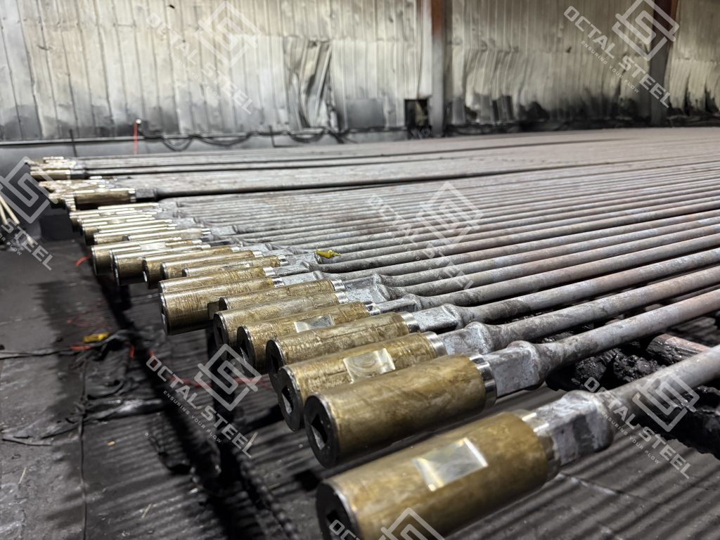
Sucker Rod
As a sucker rod manufacturer supplying API 11B, Octal delivers lot-traceable rods and couplings with clear grade marking and proven connection options.
Outer Diameters: 5/8” to 1 3/4”.
Grades: C, K, D, KD, HL, HY.
Material: AISI 4130M, AISI 4138M, AISI 4330M, AISI 4142M, AISI 8630
Sucker Rods Length: 25 ft or 30 ft
Pony Rods Length: 2 ft to 10 ft.
Ends Type: Class T coupling, Reduced Diameter, SM coupling.
Rods Type: Sucker Rods, Pony Rods, Polished Rods, Sinker Bar, Drive Sucker Rod, Centralized Sucker Rod, Anti-Twist Sucker Rod
Sucker Rods API Specs. 11B, in Grades C, K, D, KD, HL, HY, High Strength Rods in AISI 4330M, and AISI 4138M, AISI 8630 and etc.
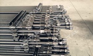
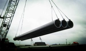
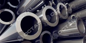
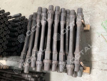
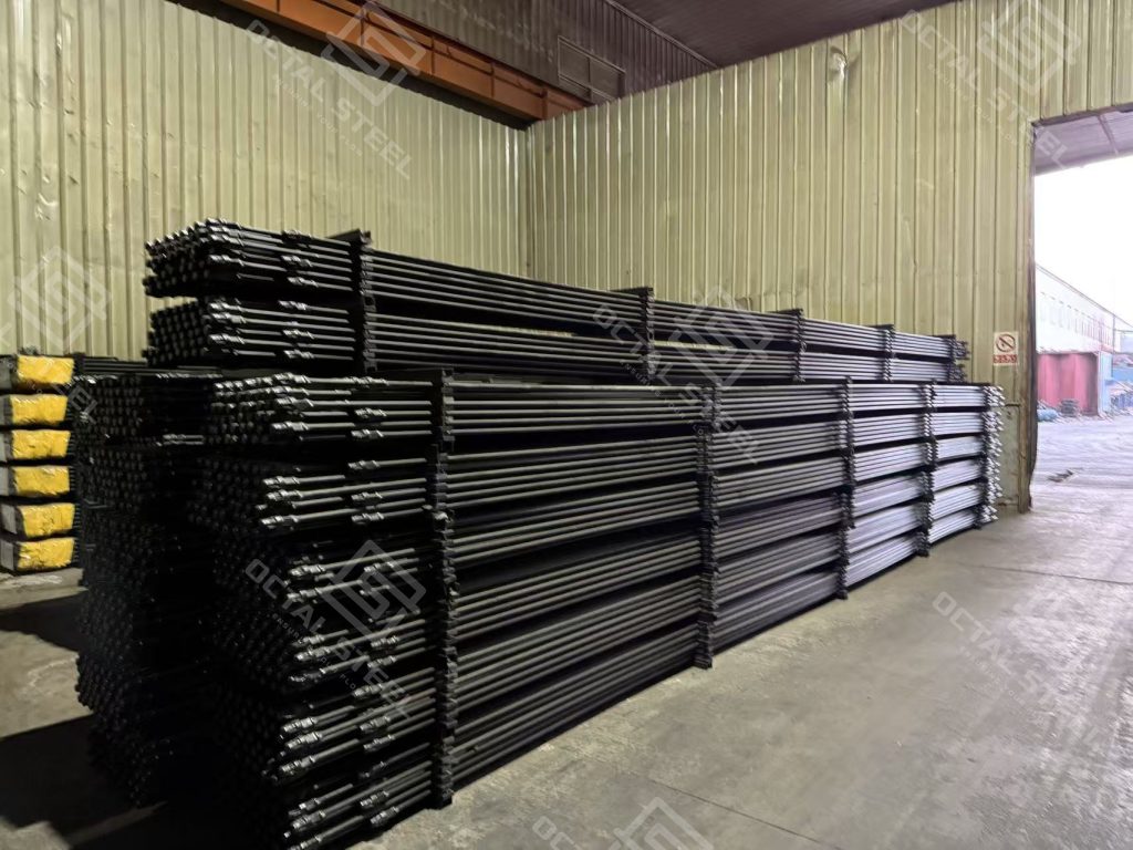
sucker rod is a long, slender rod used in the oil and gas industry, typically 25–30 ft long (5/8″–1-3/4″ OD), primarily in pumping systems for extracting oil from wells. It connects the surface pumping unit to the downhole pump, transferring the mechanical energy needed to lift the oil to the surface. Sucker rods are typically made of steel and are designed to withstand the harsh conditions of the well environment, including high pressures and corrosive fluids.
In service, the rod string operates under cyclic tensile loading with stress concentration at upset ends and threaded connections. Most premature failures trace back to a small set of controllable variables—grade selection for load and corrosion, connection consistency, and surface protection—because a single weak point can stop the well and trigger a full work-over cycle.
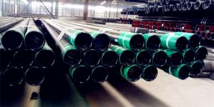
Sucker rod in API 11B for sale
Octal has high strength API 11B sucker rod for sale in Grade C, K, D, KD, HL, HY. Material available in alloy steel AISI 4130M, AISI 4138M, AISI 4330M, AISI 4142M, AISI 8630, with high strength and anti-torsion performances. API 11B specification includes the technical requirements for Sucker Rod, Pony Rod, Drive Rod, Polished Rod, Sinker Bar.
Typical deliverables include rods and matching couplings by size, protective thread caps, clear marking, and lot-based documentation that links each shipment to its Material Test Report (MTR). For procurement releases, the key is alignment between grade/material, thread form, coupling type, and inspection records so string assembly and acceptance can be closed without rework.
Sucker Rod Specifications / Common Features
Construction
Made of high-quality carbon or alloy steel to handle strong pulling and pushing forces in drilling and production. Available in different grades and sizes.
Construction choices are driven by three realities underground: high-cycle fatigue, corrosive well fluids (H2S/CO2/chlorides), and side loading in deviated wells. Steel sucker rods remain the API 11B baseline for most rod-pumped wells because the fatigue performance of upset ends and connections can be controlled and verified lot-by-lot through mechanical testing and process records.
Length and Diameter
Typically 25–30 feet (7.6–9.1 m) long. Diameters commonly range from 5/8 inch to 1-1/4 inches (15.9–31.8 mm).
Standardization matters in purchasing: mixing OD steps and length sets changes rod-string weight, stretch, and connection count, which directly affects load distribution and fatigue accumulation. Pony rods (2–10 ft) are commonly used to fine-tune string length and to manage localized wear zones without replacing full-length rods.
Types
Conventional sucker rod (solid)
Hollow sucker rod (has a hollow center for fluid flow)
Continuous sucker rod (one long piece with no threaded joints)
Type selection is usually tied to the dominant failure driver. Continuous sucker rods reduce the number of threaded joints, which lowers joint-related corrosion and fatigue initiation points. Centralized/guide solutions are often specified where deviation-driven wear is the limiting factor, while anti-twist designs are used when torsional effects and connection back-off risk become material.
Function
Transmit mechanical power from the surface to downhole pumping equipment.
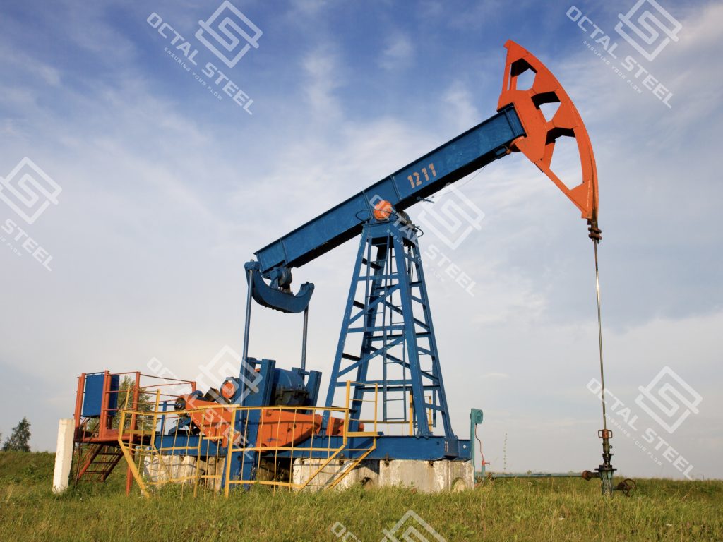
Pumping Mechanism: In a typical setup, the sucker rod is attached to a pumping unit, such as a pumpjack, which reciprocates the rods up and down to create the necessary pumping action. This action helps lift the oil or gas to the surface.
From a performance standpoint, the rod string is a mechanical transmission line: load reversals, string weight, and frictional drag combine into peak stress at connections and upset transitions. That is why connection geometry, thread finish, and consistent make-up behavior are treated as acceptance-critical items, not just machining details.
Pumping System Basic Operation Flow as below
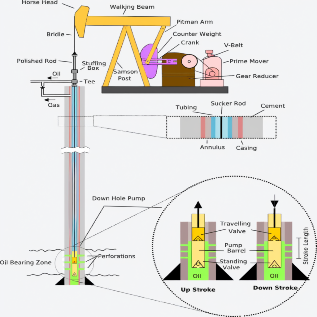
- System Overview: A crank and connecting rod drive the sucker rod to move up and down in deep wells.
- Operating Mechanism:
- Downstroke: Creates negative pressure.
- Upstroke: Lifts oil to the surface through production tubing.
Technical Characteristics:
- Operating Load: 15-45 kN
- Temperature Range: -40°C to 150°C
- Suitable for: Conventional oil fields, offshore platforms, high water cut wells
- Key Advantages: High strength, corrosion resistance, precise connections
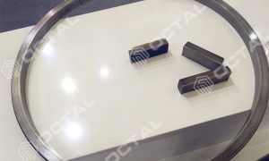
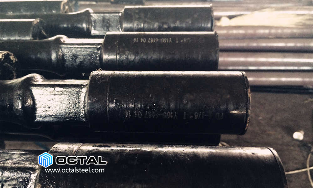
Threaded Connections
Sucker rods have threaded connections on each end, allowing them to be joined together to form a continuous string. The connections are usually made using a coupling or a rod clamp, ensuring a secure and leak-free connection.
Connection reliability depends on thread form accuracy, surface finish, and gauge compliance across both rods and couplings. In field runs, most connection-related issues show up as inconsistent make-up, accelerated coupling wear, or fatigue cracking initiated at the first engaged thread—especially when corrosion and cyclic loads act together.As a sucker rod manufacturer, Octal verifies thread form with gauge-based checks to keep make-up behavior consistent across lots.
Connection Options (Couplings & Threads)
| Option | Typical use | Inspection focus |
|---|---|---|
| Class T coupling | Standard rod-string connections for general service | Thread gauge compliance Surface finish at thread roots and shoulders Make-up consistency across lots |
| Reduced Diameter coupling | Applied where clearance and wear exposure are sensitive (often in deviated sections) | OD consistency and surface condition Thread compatibility with rod ends Wear and coating integrity at coupling OD |
| SM coupling | Used where connection performance and make-up repeatability are emphasized | Thread form accuracy and gauge records Surface finish and defect control Lot-based traceability for rods + couplings |
Sucker Rod Manufacturing Processes
For a sucker rod manufacturer, the practical differentiator is process consistency that can be proven by records: raw bar verification by heat, controlled upsetting for sound flow lines at the rod end, quench-and-temper stability by lot, CNC thread accuracy with gauge control, and final inspection that ties dimensions, NDT scope, and mechanical results back to a traceable MTR.
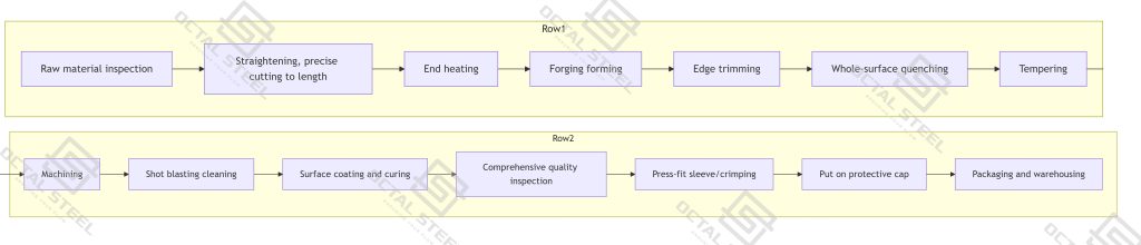
- Raw material inspection
- Straightening, precise cutting to length
- End heating → forging forming → edge trimming
- Whole-surface quenching → tempering
- Machining (turning/threading/milling with square corners)
- Shot blasting cleaning
- Surface coating and curing
- Comprehensive quality inspection (dimensions, NDT, performance)
- Press-fit sleeve/crimping
- Put on protective cap
- Packaging and warehousing
Key processes Forging, Heat Treatment, Threading(/h2)
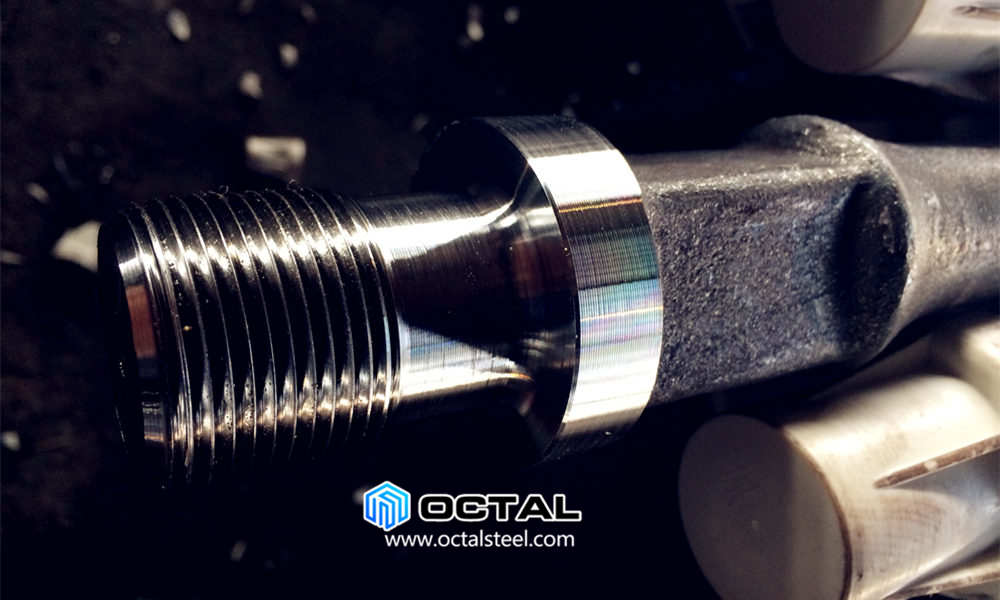
Forging Forming
• Purpose: To create an extremely strong, defect-free end on the sucker rod (for connecting to other rods and couplings).
• Process: The end of the precisely cut rod is locally heated to a forging temperature (approx. 1200°C) in an induction heater. It is then placed into a die and upset and formed under immense pressure, creating a shoulder larger in diameter than the rod body.
• The metallographic structure and flow lines formed during hot forging directly determine the fatigue strength and connection reliability. If improperly executed, the process can easily lead to defects such as cracking, inclusions, and excessive stretching.Identification markings must be clear and associated with the Material Test Report (MTR) and batch number, ensuring complete traceability upon product delivery.
• Why it’s Important:
⒈High Strength: The forging process refines the grain structure and makes it flow continuously along the shape of the part. This eliminates defects like porosity, significantly increasing the fatigue strength and load-bearing capacity of the upset end.
⒉Reliability: This is one of the most critical steps to ensure the rod does not fail under the repeated tensile loading cycles it endures downhole.
⒊Inspection focus: upset geometry consistency, surface quality at transition, and evidence of defect control in the lot inspection record.
⒋Acceptance relevance: upset-end integrity is the dominant driver of fatigue life because it sees the highest cyclic stress concentration during operation.
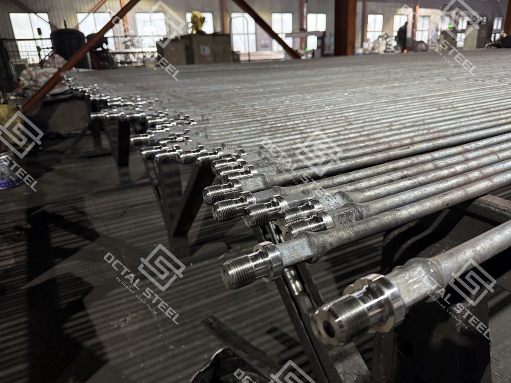
CNC Threading
Purpose: To machine the threaded sections and rod body to very high precision.
• Process: A Computer Numerical Control (CNC) lathe is used to precisely cut the forged end according to a programmed blueprint. This creates the high-precision connection threads (e.g., API Modified Square Thread) to exact standards.
• Why it’s Important:
⒈Precision & Consistency: CNC technology ensures every rod’s threads have consistent dimensions, form, and pitch. This is essential for creating tight, secure connections between rods and preventing downhole failures.
⒉High Efficiency: Automated machining is stable and efficient, ideal for large-scale production.
⒊Surface Quality: It produces an excellent surface finish, reducing stress concentration points and extending fatigue life.
⒋Gauge compliance: thread form and pitch verification reduces mismatched make-up behavior between rods and couplings across different lots.
⒌Failure prevention: consistent thread root finish and controlled surface condition reduce crack initiation risk under combined load and corrosion.
Heat Treatment
Purpose:Achieve design-specified mechanical properties (strength, toughness, fatigue resistance) through heat treatment techniques such as quenching, tempering (or normalizing, annealing, quenching and tempering).
• Process: Normalization → Quenching (heating to austenitic temperature and rapid cooling) → Tempering (heat at specified temperature to reduce brittleness and adjust hardness)
• Critical Control Parameters:
⒈ Heating temperature
⒉ Holding time
⒊ Cooling medium
⒋ Tempering temperature and duration
⒌ Heating and cooling rates
• Why it’s Critical:
⒈ Creates Core Properties: Quenching makes the rod extremely hard and strong, while tempering reduces brittleness and adds toughness.
⒉ Ensures Reliability: This process (called quenching and tempering) is what enables the sucker rod to withstand millions of repetitive stress cycles underground without stretching or breaking
⒊ Lot consistency: mechanical properties are evaluated as a distribution by heat/lot, not as a single data point, because mixed hardness/strength widens fatigue scatter in the string.
⒋ Documentation: heat-treatment traceability (cycle identification and lot records) supports acceptance when mechanical values are verified against API 11B requirements.
Common Sucker Rod Problems and Root Causes
Failure Mode Matrix
| Failure mode | Common drivers & where it starts | Controls typically specified (spec/QA) |
|---|---|---|
| Corrosion / pitting | CO2 / H2S / high-chloride water Crevice effects at couplings and upset transitions Often initiates at threads/shoulders |
Grade/material matched to service Coating/surface protection scope defined Lot traceability (marking ↔ MTR ↔ packing list) |
| Fatigue cracking | High-cycle tensile loading Stress concentration at upset transitions and first engaged thread Accelerated by corrosion and inconsistent make-up |
Heat-treatment consistency by lot (MTR mechanical ranges) Thread form & surface finish control Gauging and connection compatibility for rods + couplings |
| Mechanical damage | Handling impacts and tool contact Defects at upset ends, shoulders, thread roots |
Protective caps and packaging controls Receiving inspection focus on ends/threads Defined visual acceptance criteria for damage |
| Wear / coupling wear | Deviation and friction zones Rod-on-tubing and coupling contact Often shows first on couplings and localized rod sections |
Rod type aligned to deviation/wear risk (e.g., centralized/continuous where applicable) Coupling type selection and gauge control Surface protection integrity verification at receipt |
Corrosion-related failures
• Often associated with CO2/H2S service, high-chloride produced water, and localized crevice conditions at couplings and upset transitions. Typical outcomes include section loss, pitting, and crack initiation under combined stress and corrosion.
Fatigue failure
• Driven by high-cycle tensile loading and stress concentration at connections. Fatigue cracks commonly initiate at upset transitions or the first engaged thread when make-up consistency and surface finish are not controlled.
Mechanical damage
• Handling impacts and downhole tool contact can create small surface defects that become crack starters under cyclic load. Damage is most critical at upset ends, shoulders, and thread roots.
Wear (rod-on-tubing / coupling wear)
• Deviated wells and high friction zones promote accelerated wear, often first visible on couplings and localized rod sections where side load is highest.
Deviation and bending effects
• Side loading in deviated wells increases frictional drag and bending stress, amplifying both wear and fatigue accumulation, especially when combined with corrosive fluids.
Sucker Rod material chemical and strength
Materials
- Sucker rods are made from carbon steel or alloy steel.
- Common alloy steels include: AISI 4130M, 4138M, 4330M, 4142M, 8630M, and related ANSI 41XX grades (e.g., 4138M, 4330M, 4142M).
- Each grade has a specific chemical composition and mechanical properties (tensile strength, yield strength, hardness, toughness, etc.).
- Selection depends on needed strength and service conditions.
Sucker Rods in API 11B Standard Specification
Please note above values are for references, in case specific order, manufacturer maintain the reservation to modify it.
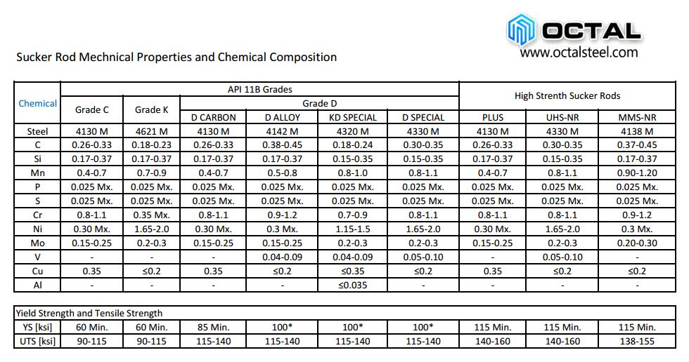
API 11B sucker rod grades in C, K, D, mechanical properties as below:
a. Grade C sucker rod minimum and maximum tensile strengths of 90,000 and 115,000 psi, respectively.
b. Grade K: 90,000 psi to 115,000 psi. These rods are made with 1.65 to 2.00% nickel alloy, therefore, it is more expensive than Grade C but has improved corrosion-related properties.
c. API 11B Grade D sucker rod tensile strength minimum 115,000 psi and maximum 140,000 psi. Grade D covers three types of material: Carbon steel, alloy steel, and special-alloy steel.
Mechanical property confirmation is normally closed on the MTR for the specific heat/lot shipped, including chemistry and tensile range by grade. For procurement clarity, grade naming (C/K/D and higher-strength variants) should remain consistent across marking, MTR, and packing list so that field string design and acceptance checks stay aligned.
Corrosion Protection
Sucker rods are susceptible to corrosion due to exposure to well fluids and harsh downhole conditions. To protect against corrosion, the rods are often coated with protective coatings or treated with corrosion inhibitors.
Corrosion in rod strings is commonly driven by CO2 corrosion, H2S-related mechanisms, high-salinity produced water, and microbiological activity, with couplings and upset ends often becoming early hotspots due to crevices and local stress. Corrosion protection is therefore evaluated as a system—material/grade chemistry, surface treatment or coating integrity, and how well documentation and marking preserve lot segregation throughout storage and handling.
Maintenance and Inspection
Regular maintenance and inspection of sucker rods are essential to identify any signs of wear, corrosion, or damage. Damaged rods should be replaced promptly to ensure safe and efficient well operations.
Receiving Inspection Highlights (typical acceptance focus)
• Marking and traceability: rod/coupling ID matches heat/lot on MTR and packing list.
• Dimensional checks: OD, length, straightness, and upset geometry consistency by lot.
• Thread and coupling fit: gauge verification and visual surface condition at threads and shoulders.
• Surface condition: coating continuity, handling damage, and cap protection integrity.
This sucker rod manufacturer workflow is built around thread gauging, dimensional checks, and lot-based documentation mapping.
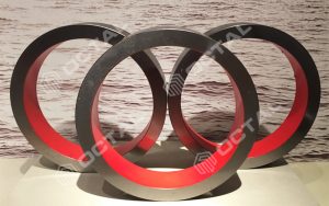
Sucker Rods Coupling Types
with the connection T coupling or reduced diameter coupling. sucker rod connect each other and extended to an under ground piston of the reserve oil, by the reciprocating motion to pump the oil.
Overall, sucker rods play a crucial role in the oil and gas industry, providing the mechanical power necessary for the extraction of oil and gas from underground reservoirs.
Couplings are frequently the first location where combined corrosion, wear, and fatigue interact, because they see localized stress and crevice exposure around threads. Matching coupling type and material to the rod grade, plus gauge-controlled thread compatibility, is typically treated as a single acceptance package rather than separate line items.
Drive Rod
Drive rods transmit power in drilling and drive systems and are built for higher torsional/rotational loads, both downhole and on the surface. They generally come in bigger sizes than sucker rods.
- Sucker rods: typical outer diameters from about 1/4″ to 1-1/2″ (light-duty) and up to ~2″ for standard production rods. Heavier grades exist for high load.
- Drive rods: outer diameters mainly from 1″ to 4″, chosen by load, torque, and equipment. Larger diameters are used for heavy-duty drilling or surface drive.
Drive rods are evaluated differently from sucker rods because torsional capacity and rotational loading become dominant. Keeping drive-rod requirements separated from sucker-rod purchase specs helps avoid misapplication where tensile/fatigue design should remain the primary control.
Pony Rod
• A pony rod is a short sucker rod, usually under 10 ft in length.
• Its application is similar to sucker rods for oil pumping, providing short pieces to complete the oil well system or drilling context where a short rod is needed.
• It is considered an auxiliary rod used in the well pumping process, serving as a linkage in rod strings or surface equipment.
• Materials are similar to sucker rods (carbon or alloy steel).
Pony rods are commonly purchased as a practical inventory item because they allow string-length adjustments and targeted replacement at high-wear sections without changing the full rod-string configuration. Traceability and connection compatibility remain the same as full-length rods to keep make-up behavior consistent.
Pony rod is short piece of sucker rod.
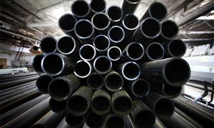
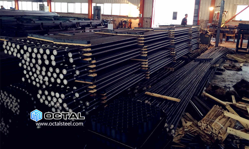
Sucker Rod Raw Material
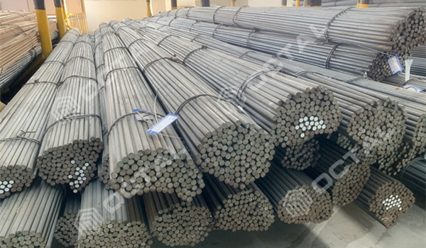
Sucker rod is making from steel rod by forging and threading.
Raw material control is the start of acceptance: heat identification on the bar, chemistry/mechanical verification, and lot segregation carry forward into forging, heat treatment, threading, and final inspection. When traceability is maintained end-to-end, shipment documentation can be mapped cleanly to installed strings and post-run analysis.
Dimensions and Grades of sucker rods for Sale
API 11B sucker rod for sale in below grade and dimensions.
Outer Diameters:5/8 in, 3/4 in , 7/8 in, 1 in, 1 1/8 in, 1 1/4 in, 1 1/2 in, 1 3/4”.
Length: 25 ft or 30 ft
Pony Rods Length: 2 ft, 4 ft, 6 ft, 8 ft, 10 ft and customized.
Ends Type: Class T coupling, Reduced Diameter, SM coupling.
Thread: PIN X BOX, PIN X PIN
Special Sucker Rods: Hollow sucker rod, polished rod
Continuous rod: Threaded, socket sucker rod
Drive Sucker Rod
Sinker Bar
Centralized Sucker Rod
Anti-Twist Sucker Rod
For procurement, the ordering essentials typically include OD, length set (25 ft / 30 ft plus pony rods), end style and coupling type, thread configuration, grade, and material option where applicable. Keeping these elements fixed across the lot reduces mixed-string variability, which is a common source of inconsistent make-up and uneven fatigue accumulation.
Standard Supply Range (API 11B sucker rod for sale)
| OD (in) | Standard length set | Common make-up options |
|---|---|---|
| 5/8, 3/4, 7/8 | Rod: 25 ft / 30 ft Pony rod: 2–10 ft |
Ends: Class T / Reduced Diameter / SM coupling Thread: PIN×BOX, PIN×PIN (as specified) Docs: MTR + packing list traceability |
| 1, 1 1/8, 1 1/4 | Rod: 25 ft / 30 ft Pony rod: 2–10 ft |
Grade: C / K / D / KD / HL / HY Material options per order (4130M/4138M/4330M/4142M/8630) |
| 1 1/2, 1 3/4 | Rod: 25 ft / 30 ft Pony rod: customized lengths available |
Applied where load demands and string design require larger OD Acceptance closed by lot-based MTR and inspection records |
Applications for different grades
As we know in API 11B there are Grade C, K, D, more over there are high strength sucker rods with Standard SY/T5029-2006 covers grades in KD, HL, HY; KH level rod will be complied with manufacturer internal protocols.
Below applications for each grades:
1. Grade C sucker rod is mainly used for light, medium load, no corrosion or corrosion shallow Wells or in deep well pumping, material is carbon steel or manganese steel.
2. Grade D sucker rod is made of high quality alloy steel, after heat treatment with high strength, plasticity is good, long life and other characteristics, it is suitable for light when there is no corrosion or corrosive medium in the deep Wells under the environment of use.
3. Grade H(HL and HY) sucker rod is made of high quality alloy steel manufacturing, have the characteristics of ultra high strength, used in deep well, big strong pump used in production.
4. K and KD sucker rod with different content of Ni Cr – Ni – Mo high quality alloy steel manufacturing, have anti-corrosive, resistance to corrosion function, respectively applicable to strong corrosion of shallow, middle and deep Wells.
Across most projects, grade selection follows the dominant limiting factor: corrosion exposure pushes the decision toward corrosion-tolerant grades and protection systems, while deeper/high-load wells push toward higher-strength grades with controlled heat treatment consistency. In deviated wells, wear control and connection reliability often outweigh pure tensile numbers because side loading accelerates coupling wear and fatigue initiation.
Grade vs Well Condition (Selection Matrix)
| Grade family | Best-fit condition (typical) | Primary risk addressed |
|---|---|---|
| Grade C | Light to medium load wells Low to moderate corrosion exposure |
Baseline tensile capacity with cost-effective supply control |
| Grade K / KD | Corrosive wells (CO2/H2S/chlorides) Where corrosion-related performance is prioritized |
Corrosion tolerance and reduced corrosion-driven failures at connections |
| Grade D | Deeper wells / higher load demand Where higher tensile capacity is needed |
Strength margin and fatigue performance when heat-treatment consistency is controlled |
| HL / HY (high strength) | Deep wells and high-load pumping systems | High-load capability (string design driven by load + deviation + corrosion combined) |
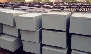
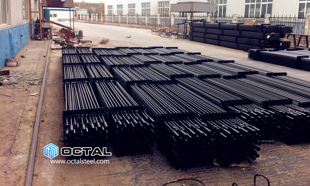
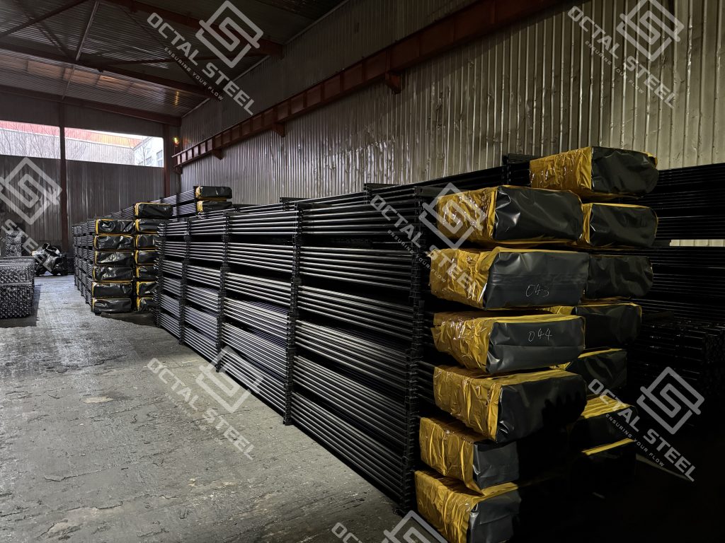
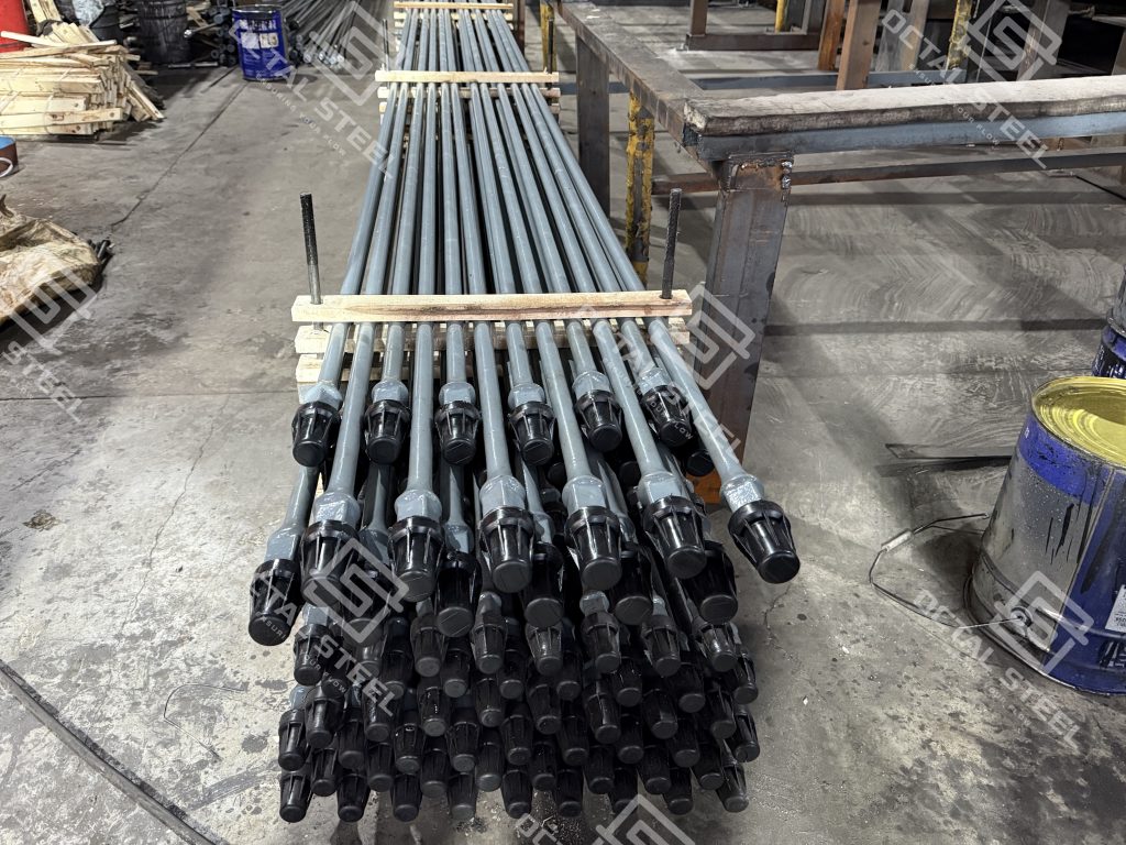
Package Types
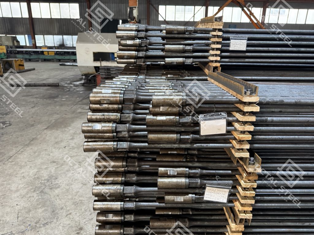
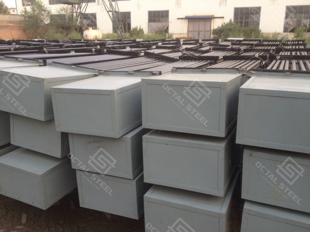
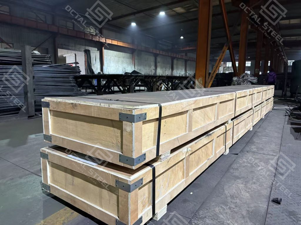
Packaging is part of acceptance control for rod strings. Typical shipment practice includes thread caps, protective separation to prevent coating damage, clear bundle marking, and packing lists that map bundle IDs to MTR heat/lot data. When marking, caps, and documents remain consistent, incoming inspection and warehouse segregation can be closed faster and string assembly stays predictable.
Acceptance-Ready Package: Traceability, Gauging, and Protection
Octal as a market-leading China sucker rod manufacturer structures its API 11B sucker rod for sale supply as a single release package—rods, matched couplings, and traceable paperwork—so receiving and string assembly can be closed by lot. Each bundle is marked with heat/lot ID, and the packing list maps bundle numbers to the same heat/lot shown on the MTR; couplings are supplied by size/type with consistent identification (e.g., Class T / Reduced Diameter / SM as specified). From a sucker rod supplier’s perspective, Octal’s process records typically follow the lot from raw bar heat ID through upsetting and quench-and-temper to CNC threading, with thread form verified using API gauges (GO/NO-GO) to keep make-up behavior consistent across the string. A typical acceptance pack can include MTR by heat/lot, a dimensional summary, and thread gauge logs, so the purchase spec, markings, and documents align without rework. Threads ship with protectors and separated packing to reduce shoulder/thread damage and preserve coating condition through transit and storage.
FAQ
Q1: What documents are typically included with an API 11B sucker rod for sale shipment?
A1: A standard acceptance package commonly includes the Material Test Report (MTR) by heat/lot, shipment marking that links rods and couplings to the same lot, and a packing list that maps bundle IDs to the traceability documents for receiving and release.
Q2: How do corrosion conditions change the selection between Grade C, K/KD, and higher-strength rods?
A2: Corrosive fluids (CO2/H2S/high-chloride water) tend to shift the priority toward corrosion-tolerant grades and protection scope, because couplings and upset transitions are frequent corrosion hotspots; higher-strength grades are typically chosen when load and depth dominate, with heat-treatment consistency remaining acceptance-critical.
Q3: What are the most important acceptance points for threaded connections and couplings?
A3: The highest-impact points are thread gauge compliance, surface condition at thread roots and shoulders, and lot-based compatibility between rods and couplings, because connection behavior directly affects make-up consistency, coupling wear, and fatigue crack initiation.
Q4: When is a continuous sucker rod specified instead of conventional threaded rods?
A4: Continuous sucker rods are commonly used when joint-related risk is dominant, because reducing the number of threaded joints lowers corrosion and fatigue initiation points; conventional rods remain common where standardization, inventory flexibility, and conventional field make-up practices are preferred.