Your Responsible Supplier Partner for Oil and Gas Products.
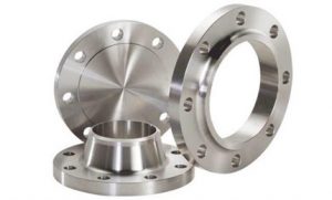
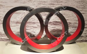
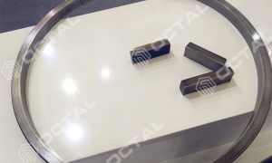
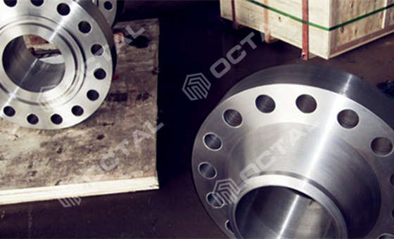
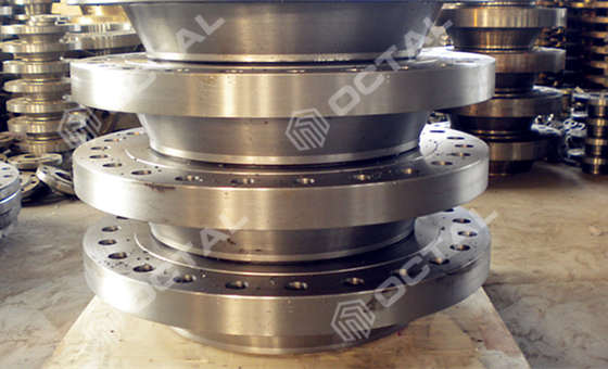
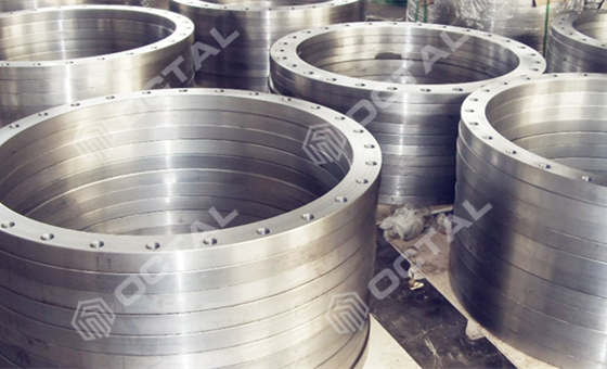
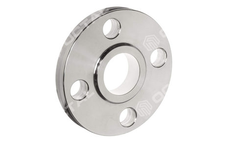
Pipe Flange (Carbon & Alloy Steel, ASTM A105/A182)
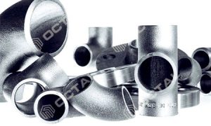
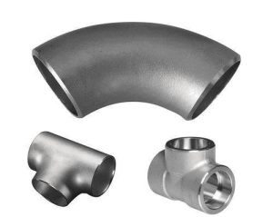
Recent Products

Rencent Articles


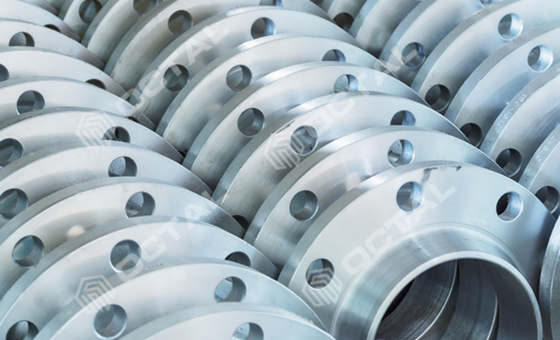
Pipe Flange (Carbon & Alloy Steel, ASTM A105/A182)
Range of Sizes: 1/2” to 40”, DN10 to DN3000 for pipe flanges
Range of Thickness: SCH5 to SCH160 for pipe flanges
Pressure range for pipe flange: Class 150, Class 300, Class 600, Class 900, Class 1500, Class 2500; PN 0.6 MPa to PN 42 MPa
Facing types: Raised Face (RF) – RTJ – Flat Face (FF)
Slip on Flange, Weld Neck Flange, Socket Welding Flange, Thread Flange, Blind Flange, DN Flange available.
Pipe flange is a bolted mechanical connector used to join pipes, valves, and equipment, enabling repeatable assembly, maintenance access, and controlled sealing with a gasket. In oil & gas and industrial piping, most pipe flanges are supplied in carbon and alloy steel (such as ASTM A105 and ASTM A182), with stainless options available for corrosive service, and are specified by pressure class, facing type, and dimensional standard.
Typically made from carbon steel (ASTM A105), Alloy steel (ASTM A182), and stainless steel (304L, 316L) In different dimensions and pressure class.
Why Steel Flanges are Used:
• Connection
Pipe flanges provide a reliable method to connect pipes, valves, and equipment, forming a secure joint designed to handle specified pressure and temperature conditions.
• Ease of Assembly and Maintenance
Bolted flange joints allow disassembly for inspection, maintenance, or replacement of pipe sections without cutting the line.
• Pressure and Temperature Capability
Flange ratings and material grades are selected to match pressure-temperature requirements and service media.
• System Flexibility
Pipe flanges support modular design, allowing the addition of valves, instruments, and branch connections with standardized interfaces.
How Steel Flanges Work:
- Installation:
- Flanges are typically welded or bolted onto the ends of pipes. For welded flanges, the flange is attached to the pipe’s end through welding, providing a strong bond. For bolted flanges, they are aligned and fastened together using bolts and nuts, often with a gasket in between to ensure a tight seal.
How many parts included in a flange connection?
A flange connection typically includes several key parts:
- Flanges: The main components that are bolted together. There are usually two flanges, one on each side of the connection.
- Gasket: A sealing material placed between the two flanges to prevent leaks. It compresses when the flanges are bolted together.
- Bolts: Used to fasten the two flanges together. The number and size of bolts depend on the flange size and pressure rating.
- Nuts: These are paired with the bolts to secure the flanges tightly together.
- Washers (optional): Sometimes used under the nuts to distribute the load and prevent damage to the flange surface.
In summary, a typical flange connection consists of two flanges, a gasket, bolts, and nuts, with optional washers.
Failure modes
- Leakage:
- Often caused by improper installation, inadequate torque on bolts, or gasket deterioration, leading to fluid loss and potential safety hazards.
- Gasket Failure:
- Gasket material can degrade due to temperature fluctuations or chemical exposure, resulting in loss of sealing capability.
- Bolt Failure:
- Over-tightening, corrosion, or fatigue can lead to bolt breakage, compromising the integrity of the flange connection.
- Flange Warping or Cracking:
- Excessive thermal stress or manufacturing defects can cause flanges to warp or crack, leading to misalignment and leakage.
- Corrosion:
- Exposure to corrosive substances can weaken flange material over time, leading to structural failure.
- Fatigue Failure:
- Repeated loading and unloading cycles can cause material fatigue, resulting in cracks and potential failure.
- Improper Alignment:
- Misalignment during installation can lead to uneven stress distribution, increasing the risk of leakage and mechanical failure.
Understanding these failure modes is crucial for maintaining the integrity of flange connections in piping systems. Regular inspection and proper installation can help mitigate these risks
Flange types
According to the connection way between the pipe and flange, the flange can be divided into the following five basic types:
Slip on Flange
Weld Neck Flange
Socket Weld Flange
Thread Flange
Blind Flange
DN Flange
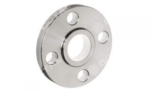
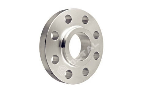
Slip-on Flange
A slip-on flange (SO flange) connects by sliding the pipe into the flange bore and applying fillet welds—typically at the outside and, where specified, at the inside as well. Because the flange ID is slightly larger than the pipe OD, fit-up is relatively tolerant of small cutting and alignment variation, which is one reason slip-on designs are widely used in general piping where installation speed and cost control are important. Common facings include Raised Face (RF) and Flat Face (FF), with other facing configurations available when the specification requires them.
From a performance standpoint, a slip-on pipe flange is often selected for lower-pressure, general-temperature service where piping loads are moderate and the joint is not dominated by cyclic bending or repeated thermal movement. The fillet-welded load path introduces higher local stress concentration than a butt-welded neck design, so long-term fatigue resistance and severe cyclic duty are typically evaluated more carefully than for weld neck flanges. In fabrication planning, the weld volume and access for internal fillet welding (when required) also influence productivity and inspection approach
Most used pipe flange
Slip on pipe flange is suitable for the lower pressure, general temperature and normal circumstance pipelines. It is easy to install and with lower cost/price, has been most used in the common industries.
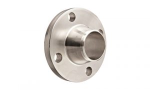
Weld Neck Flange
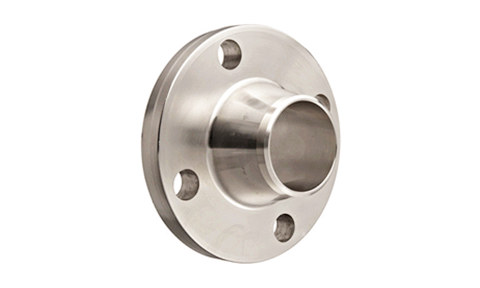
A weld neck flange (WN flange) is designed with a hub and a tapered transition that is butt-welded to the pipe end. This geometry provides a smoother stress transition from flange to pipe, which supports better performance under higher pressure, higher temperature, and dynamic loading compared with fillet-welded flange types. In the original page, the common design forms include the regular tapered-hub style and a higher-hub configuration used for higher loading or specific layout needs.
Functionally, the butt weld on a weld neck flange aligns well with quality control expectations on critical services because it is compatible with volumetric NDE approaches typically used on butt welds (as required by project ITPs). The trade-off is that weld neck flanges usually require tighter fit-up discipline—bevel preparation, alignment control, and welding procedure selection—so the installed cost can be higher than slip-on flanges even when the flange unit price is similar.
Threaded Flange
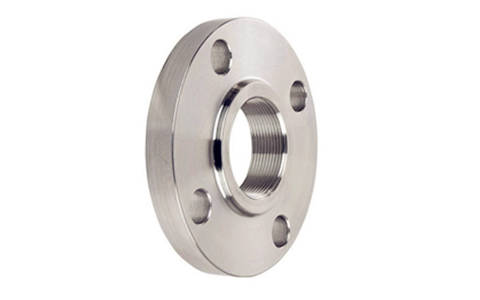
A threaded flange has internal pipe threads that mate with an externally threaded pipe end, forming a mechanical joint without welding—most commonly specified as NPT (taper) or BSPT/BSPP depending on regional practice and project standards. Its main advantages are practical and site-driven: it eliminates hot work and weld QA/NDE, shortens installation time, and suits maintenance or retrofit situations where welding access is limited or permits are restricted. It also works well for small-bore utility lines and temporary tie-ins, and it can be a straightforward option when the line is pre-threaded and the goal is fast assembly with standard tools rather than shop welding.
Sealing depends on thread engagement quality and controlled makeup, typically supported by a thread sealant (PTFE tape/paste or pipe dope), so performance is highly sensitive to thread form accuracy, concentricity, thread damage, and torque consistency. Because both the load path and sealing path run through the threads, threaded pipe flanges are generally not preferred for severe cyclic duty or high-vibration service, where micro-movement can relax thread contact and open leak paths over time.
They are also typically avoided in temperature extremes—commonly above 260°C or below -45°C—because thermal expansion/contraction, sealant limitations, and reduced thread contact stability increase leakage risk and make disassembly more problematic. In corrosive environments, the threaded crevice can accelerate localized corrosion and seize the connection, so service selection should consider corrosion allowance, protective coatings, and whether a welded alternative would reduce long-term leak and maintenance exposure.
Socket Weld Flange
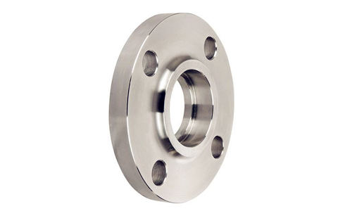
Socket weld flange (SW flange) is commonly used on small-bore piping where compact geometry and a simple weld profile are preferred. The pipe end is inserted into a recessed socket in the flange, and the connection is completed by an external fillet weld around the hub. Compared with a slip-on design, the socket feature improves axial alignment during fit-up and creates a consistent insertion depth, which can help keep joint geometry repeatable on small sizes.
In service selection, socket weld pipe flanges are often used where pressure classes are higher but pipe size is small, and where a butt-welded joint may be impractical due to access or component layout. The design does, however, create a potential crevice at the socket interface, so corrosion sensitivity and cleaning requirements are typically considered as part of material and service evaluation. On projects with strict cyclic or vibration exposure, the fillet-welded load path and local stress behavior are also reviewed against the applicable code and duty profile.
Lap Joint Pipe Flange
A lap joint pipe flange is used together with a lap joint stub end (or flanged ring). In this arrangement, the flange itself is not welded to the pipe; it slides over the stub end and can rotate freely. The sealing face is provided by the stub end, while the lap joint flange provides the bolting surface and clamp load. This rotating feature is practical when bolt-hole alignment is difficult in the field, and it reduces installation time on assemblies where orientation control is challenging.
A key functional advantage is material optimization: because the flange does not directly contact the process fluid, it is often paired with a corrosion-resistant stub end while using a more economical flange material for the rotating ring—supporting cost control on corrosive-service systems. The trade-offs usually relate to mechanical rigidity and loading: lap joint assemblies are generally evaluated more carefully for bending loads and higher stress conditions than weld neck joints, and the sealing performance is governed primarily by the stub end facing quality and gasket selection rather than the rotating ring.
Blind Flange
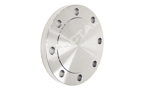
Blind flange is a solid flange with bolt holes and no bore. It is used to close the end of a pipeline, isolate a nozzle, or create a removable closure point for future access. In commissioning and maintenance planning, blind flanges are frequently used where the system may later require inspection, cleaning, tie-ins, or pressure testing.
From a functional and fabrication perspective, blind flanges are often treated as a high-integrity pressure boundary component because they carry full end load across the flange face and bolt circle. Practical considerations include gasket selection, bolt load control, and handling weight—especially as diameter and pressure class increase—since blinds can become heavy and influence rigging, alignment, and installation sequence.
Sealing types
According to different pipeline pressure and seal gasket type, there are different sealing surface types for steel pipe flange.
Flat face (FF) pipe flange
It is suitable for less pressure occasion.( PN≤1.6MPa).
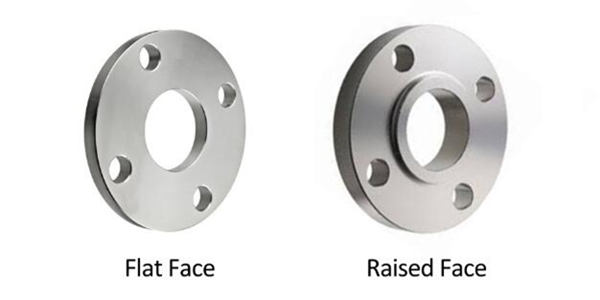
Raised face (RF) pipe flange
Sealing surface structure is simple and smooth, and easy for machining. Meanwhile it’s easy to carry out anti-corrosion lining.
However, the contact area is larger, the gasket will become squeeze on both sides easily as pre-loading. Then it will not easy to press.
Male-female (M/F) face flange
It is composed of a convex and concave surface, placing the gasket on the concave. It can prevent the gasket from being extruded. So Male-female face flanges can be applied to the higher pressure occasions.
Tongue-groove (T/G) face steel flange
The touch surface is made of tongue and groove. The gasket is placed in the slot, and it cannot be squeezed.
Comparing RF and MFM, T/G face flange can obtain good sealing effect. The structure and manufacturing of flange are more complex.
It is difficult to replace the gasket in the slot. Tongue and groove seal face is suitable for flammable, explosive, toxic medium and high pressure occasions.
Standards of steel pipe flange
Steel flange standards include European standards and American standards. Because of different dimensions, these two systems cannot interchange. American countries and China mainly adopt ASME or ANSI. Flange pressure rating in ASME could be divided into 150, 300, 600, 900, 900, 1500, 2500 grades.
Common ASME standard for flanges:
ASME B16.5
Standards for pipe flanges and flanged fittings. (Covers sizes from NPS 1/2 through NPS 24 Metric/Inch including pressure-temperature ratings, materials, dimensions, tolerances, marking, testing, and methods of designating openings for pipe flanges and flanged fittings.)
ASME B16.48
Standard for Line Blanks. (It covers all specifications for operating line blanks in sizes NPS 1/2 through NPS 24 for installation between ASME B16.5 flanges in the 150, 300, 600, 900, 1500, and 2500 pressure classes.)
ASME B16.47
Large Diameter Steel Flanges NPS 26 through NPS 60 (It covers all specifications for pipe flanges in sizes NPS 26 through NPS 60 and in ratings Classes 75, 150, 300, 400, 600, and 900.)
Pipeline Flange material specification
Pipeline Flange are commonly used for carbon steel, alloy steel and stainless steel.
Frequently used material as below:
Carbon steel: STM A105
Alloy steel: ASTM A182 F11, F22, LF2
Stainless steel: 304/L, 316/316L
We supply carbon, alloy, stainless steel pipe flange in different dimensions and pressures
Octal Supply pipe flanges in below ranges:
Range of Sizes: 1/2” to 40”, DN10 to DN3000 of steel flanges
Range of Thickness: SCH5 to SCH160 of steel flanges
Pressure range: Class 150, Class 300, Class 600, Class 900, Class 1500, Class 2500, from PN 0.6Mpa to PN 42Mpa
Type of Ends: Rased Face – RTJ – Flat Face
Steel Flange Material Standards and Grades
Carbon steel flange standards: ASTM A105, ASME A/SA 105, 350LF 2
Stainless steel flanges standards: F304, 304L, 309S, 309H, 310S, 316, 316L, 317, 317L, 321, 321H, 347, and 904L
Alloy steel flange standards: ASTM A182, ASME A182, ASME SA182, ASTM A182 F1, F11, F12, F22, F5, F9, F91
ASME B16.5, ASME B16.47, ASME B16.48, AWWA C207, MSS SP-44,
More standards available in: DIN2573, DIN2577, DIN2630, DIN2631, DIN2632, DIN2533, DIN2634, DIN2635, DIN2636
BS4054, BS3293, EN1092-1, ISO 7005
JIS B2220
HG/T20592, HG/T21516-21518
Steel Flange Applications
Steel Pipe Flange is a kind of pipe fitting to connect two pipes, or pipes and valves, or the equipment. The holes on the flange connected by the steel studs, then use the gasket in the middle for sealing between two flanges. So by the different application and style, there are slip on flange, blind flange, socket weld flange, threaded flange, weld neck flange and reducing flange.
Octal offers steel pipe flange with various kinds and applicable to different industrial areas, Oil & Gas transportaion, Chemical Plant, Power Station, Water Treatment, Refining etc.
ASTM A105, ASTM A182
![]()