Your Responsible Supplier Partner for Oil and Gas Products.
FBE Coated Pipe
Recent Products

Rencent Articles
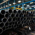

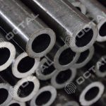


FBE Coated Pipe
Scope: defines FBE coating requirements for pipe coating by service environment and installation damage exposure.
Process window: blast clean (Sa 2½ / NACE No. 2, 50–100 μm), preheat 180–250°C, electrostatic FBE powder coating, fusion bonding cure.
Acceptance: DFT targets, holiday (jeep) testing, cutback/end protection, repair limits, and retest closure.
Standards: ISO 21809-2, AWWA C213, AWWA C550, CSA Z245.21 (project-defined), translated into inspection and documentation evidence.
Traceability: links pipe identification, coating lot/powder batch, inspection and repair logs, and packing list line items.
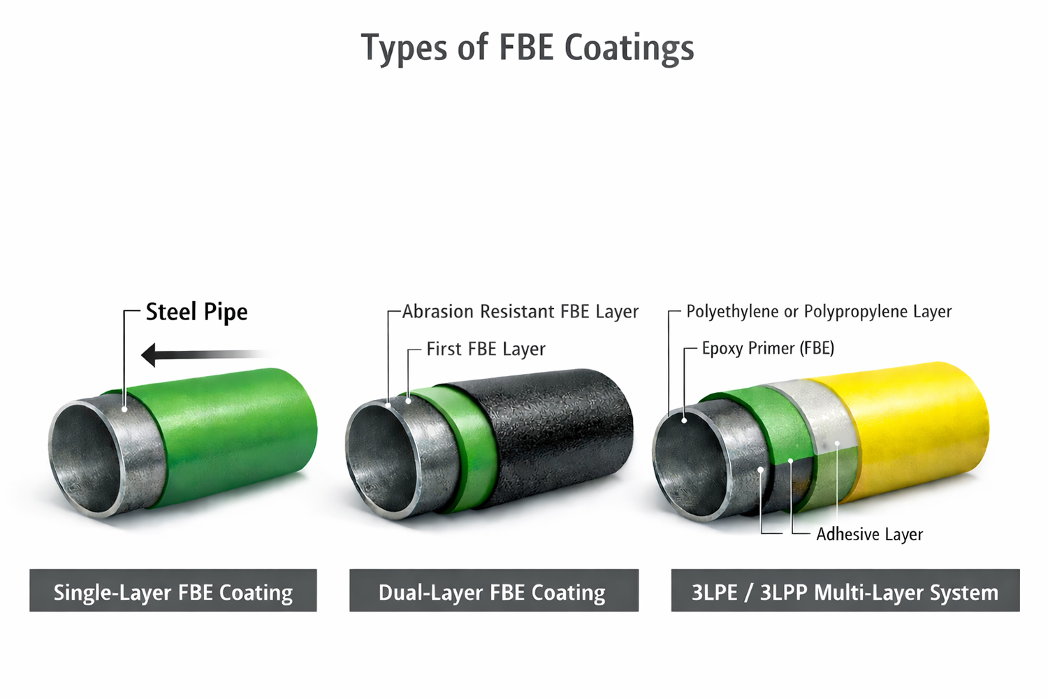
System options: single-layer FBE, dual-layer abrasion-resistant FBE, or 3LPE/3LPP (FBE as epoxy primer), plus epoxy paint boundaries for field joints and localized repairs.
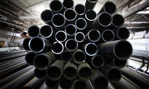
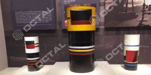
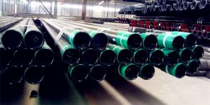
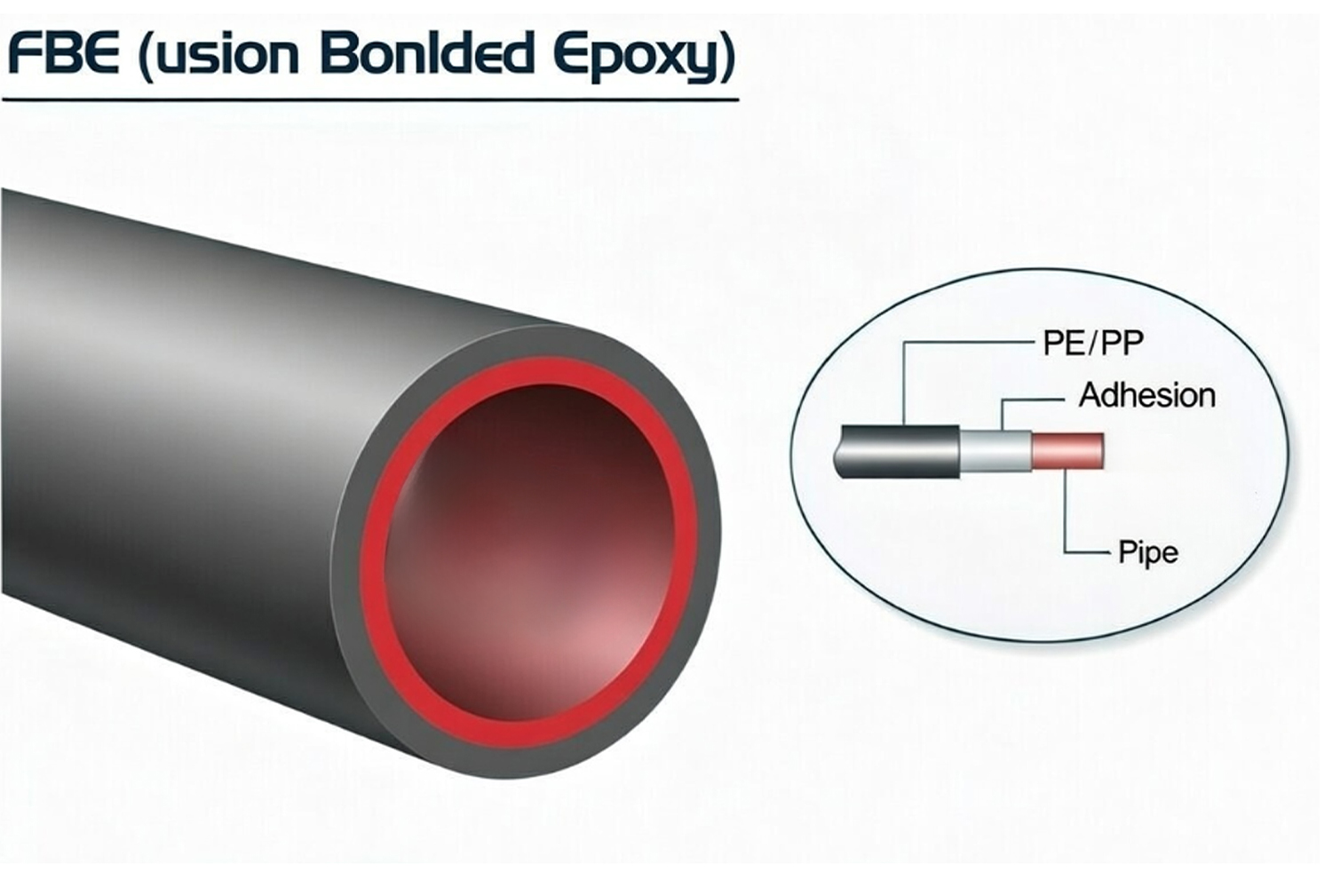
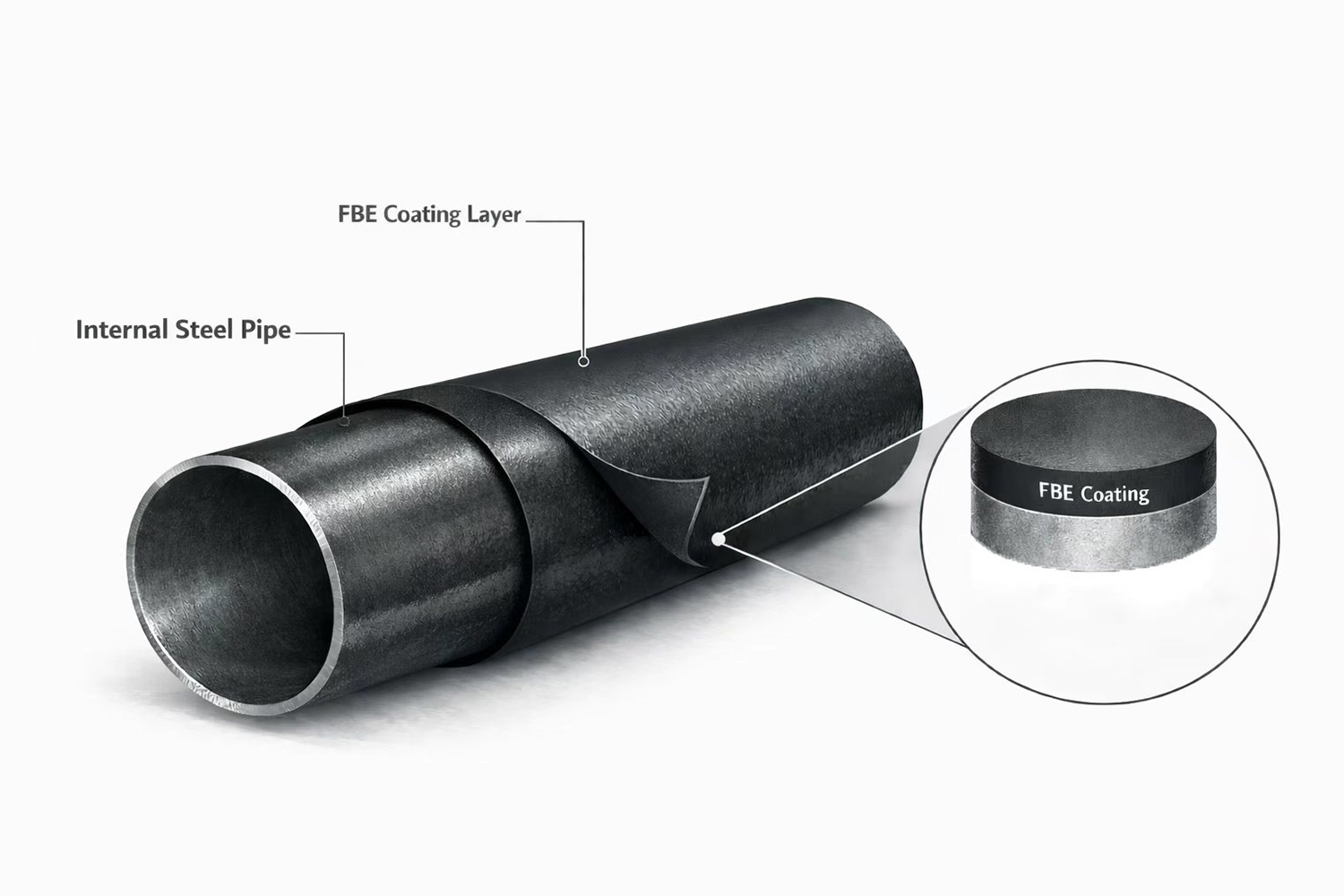
FBE coated pipe is seamless or welded carbon-steel or low-alloy steel pipe protected by a factory-applied thermosetting epoxy powder coating. The steel substrate may be manufactured by seamless, HFW/ERW, LSAW or SSAW processes to API 5L, ASTM, EN or project-specific line-pipe requirements, while the FBE system is specified separately according to operating temperature, burial or immersion conditions, installation method and mechanical-damage exposure. During production, the pipe surface is degreased, abrasive blasted to the required cleanliness and anchor profile, heated within the qualified powder-application window, and electrostatically sprayed with epoxy powder. The powder melts on contact with the hot steel, wets the blast profile, gels and chemically cross-links into a continuous thermoset film that bonds directly to the substrate.
This bonded coating limits contact between the steel and soil moisture, groundwater, dissolved salts and other corrosive species, and is commonly used together with a properly designed cathodic-protection system for buried or submerged pipelines. The term FBE describes the protective coating system only; it does not define the pipe grade, manufacturing route, wall thickness, pressure rating or mechanical properties of the base pipe.
Depending on operating temperature, installation method and mechanical-damage exposure, an FBE coated pipe may use:
- single-layer external FBE;
- dual-layer FBE with an abrasion-resistant outer layer;
- FBE as the corrosion-control primer in a 3LPE or 3LPP system;
- internal FBE lining where the service medium and applicable water or process-pipe standard require it.
External and internal FBE systems shall be specified separately. A powder qualified for buried external pipeline service is not automatically suitable for potable water, produced water, chemicals, high-temperature internal service or flow-enhancement duty.
Typical Applications
FBE coating is used where corrosion protection must remain measurable through controlled surface preparation, coating application, DFT inspection, holiday detection, repair and traceable release records.
Oil and gas pipelines:
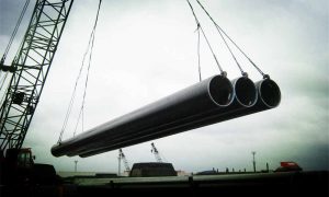
External FBE coating is applied to buried or submerged transmission pipelines, gathering lines and flowlines. The coating isolates the steel from wet soil, groundwater and dissolved ionic contamination while remaining compatible with cathodic protection. Selection should consider operating temperature, soil condition, pipe strain, field-joint design, backfill quality and the expected handling load during transport, stringing and lowering-in.
Single-layer FBE is suitable where installation damage is controlled. Dual-layer or abrasion-resistant FBE may be specified for road crossings, river crossings, horizontal directional drilling and other sections exposed to higher impact, scraping or pull-through damage.
Water and sewage pipelines:
FBE coating and lining may be applied to steel water pipe and fittings under AWWA C213 and project requirements. External coating protects buried steel against soil-side corrosion, while an internal lining must be specifically qualified for the transported water or wastewater.
For potable-water service, the specification should identify the required drinking-water approval, cure condition, allowable extraction limits, holiday-testing method, cleanliness requirement and treatment of weld ends, flanges and field joints.
Fittings and valves:
FBE can be applied to bends, tees, reducers, valve bodies and other steel or ferrous pipeline components. These products require additional inspection around edges, weld toes, body transitions, branches, cavities and irregular geometry because electrostatic shielding and local heat loss can create thin-film areas.
When valves or hydrants are included, the coating scope should distinguish between exterior FBE and protective interior coatings. AWWA C550 applies specifically to interior coatings for qualifying water-service valves and hydrants rather than acting as a general external steel pipe coating standard.
Rebar, project-dependent:
Fusion bonded epoxy is also used on reinforcing steel to reduce chloride and moisture contact in concrete structures. However, FBE-coated rebar follows rebar-specific material, bend, handling and repair standards. Rebar qualification data should not be used as acceptance evidence for an FBE coating pipe project.
Pipe Coating Specification Scope and Acceptance Items
A practical FBE coating specification connects each order field with a measurable production or inspection record. The final requirements are normally implemented through an approved inspection and test plan.
Specification snapshot for pipe coating RFQs
| Item | Typical RFQ / ITP Definition | Acceptance Focus |
|---|---|---|
| Coating system | Single-layer FBE, dual-layer FBE, abrasion-resistant FBE, or FBE primer within 3LPE/3LPP | System construction matches operating temperature, installation method and mechanical-damage exposure |
| Base pipe | Standard, edition, grade, manufacturing route, OD, wall thickness, length and end condition | Correct pipe material and geometry enter the coating line |
| Surface preparation | Cleanliness grade, qualified anchor profile, dust and soluble-contamination limits | Steel surface is suitable for stable coating adhesion |
| DFT / thickness | Minimum, nominal or permitted range, reading pattern and gauge method | Film thickness is sufficient and uniformly distributed without excessive build |
| Holiday / porosity test | Detector type, voltage basis, inspection coverage, repair and retest rules | Coating forms a continuous corrosion barrier without open discontinuities |
| Pipe ends / cutback | Cutback length and tolerance, bevel condition and temporary protection | Field welding and field-joint coating can be completed without contamination or dimensional conflict |
| Repairs | Approved repair material, preparation method, maximum repair size and mandatory reinspection | Local defects are closed under a controlled and documented process |
| Traceability | Pipe ID linked to heat number, coating lot, powder batch, inspection reports and packing list | Physical pipe remains connected to the complete release dossier |
For external single-layer FBE used on oil and gas transportation pipelines, ISO 21809-2:2026 addresses qualification, application, inspection, testing, handling and storage. AMPP/NACE SP0394-2023 provides additional industry practice for plant-applied single-layer external FBE.
CSA Z245.20:22 applies to plant-applied external fusion bond epoxy coating for steel pipe. CSA Z245.21 covers polyethylene coating and should not be used as the principal FBE coating reference.
AWWA C213-22 is applicable when FBE coatings or linings are specified for steel water pipe and fittings. AWWA C550-24 applies to protective interior coatings for valves and hydrants within its stated water-service scope.
The purchase order should state the required edition and any project supplement. Referencing a standard does not remove the need to define DFT, design temperature, cutback, repair limits, qualification testing, inspection frequency and project documentation.
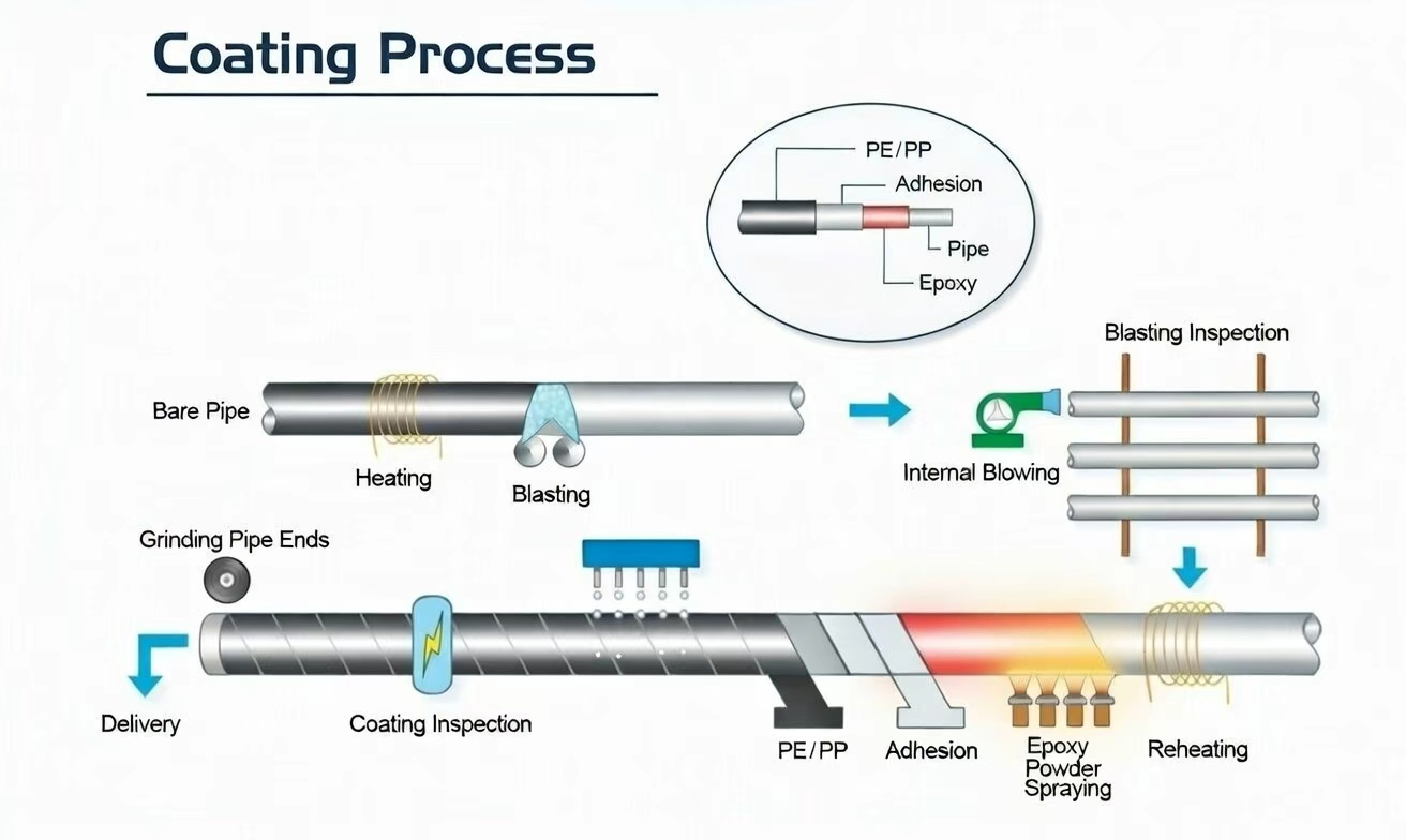
Application Process (Surface Prep, Preheat, Powder, Fusion & Cure)
FBE coating performance is established before the powder reaches the pipe. Surface condition, thermal control, powder handling and cure history must remain within the qualified process window throughout production.
1. Surface preparation
Oil, grease, temporary coatings, marking residue and other contamination are removed before abrasive blasting. Steel defects such as sharp fins, slivers, weld spatter and raised grinding edges should be corrected because a thin thermosetting film cannot reliably bridge unacceptable substrate conditions.
The pipe is then abrasive blasted to the specified cleanliness grade, commonly ISO 8501-1 Sa 2½ or SSPC-SP 10/NACE No. 2 when required by the applicable procedure. Blasting also creates an anchor profile that supports mechanical interlocking between the FBE and the steel.
Inspection may include:
- visual cleanliness comparison;
- surface-profile measurement using replica tape or a calibrated profile instrument;
- dust assessment;
- soluble-salt testing when specified;
- pipe-surface temperature and dew-point review;
- confirmation that loose abrasive and embedded contamination have been removed;
- control of the interval between blasting and coating.
The required anchor profile is determined by the selected FBE powder and qualified coating procedure. A fixed profile range should not be transferred automatically from another powder system.
2. Preheating
The cleaned pipe is heated by induction coils or another approved heating system. The steel must reach the powder-specific application window before entering the spray booth.
Temperature control should account for:
- pipe wall thickness and heat capacity;
- circumferential temperature uniformity;
- temperature variation along the pipe;
- heat loss near pipe ends and cutback areas;
- coating-line speed;
- required gel and cure time;
- calibrated infrared and contact temperature instruments.
Steel temperature below the qualified range can cause incomplete melting, poor surface wetting, weak adhesion and under-cure. Excessive temperature can accelerate gel, reduce film flexibility, damage the powder or produce an unsuitable cure condition. The production record should show actual measured temperatures rather than only the heater setting.
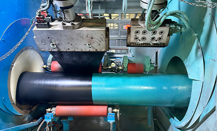
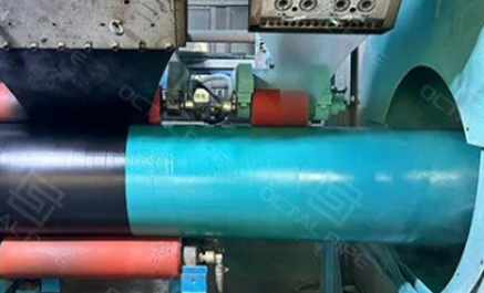
3. Electrostatic powder application
Electrostatically charged FBE powder is sprayed onto the grounded and heated steel pipe. The powder melts on contact, flows into the blast profile and joins into a continuous film.
Application controls normally include:
- powder name and batch number;
- powder storage condition and shelf life;
- virgin and reclaimed powder limits;
- spray-gun position and voltage;
- powder feed rate;
- pipe rotation or conveyor speed;
- spray-booth cleanliness;
- deposition around weld seams;
- masking and control of cutback areas;
- film build at pipe ends and geometric transitions.
Local DFT should be reviewed at weld seams, ground areas, pipe ends and other locations where surface geometry or temperature variation can affect coating deposition.
4. Cure and cooling
After application, residual heat in the steel allows the molten epoxy to gel and chemically cross-link. The required cure condition depends on the powder formulation, steel temperature history, film thickness and time before quenching.
The approved procedure should define:
- the acceptable application-temperature window;
- minimum cure or dwell time;
- line-speed limitations;
- time before water quenching;
- additional post-heating where required;
- cure-verification method;
- action following a temperature or line-speed excursion.
Differential scanning calorimetry may be used when required to evaluate powder properties, glass-transition behavior or degree of cure. The test frequency and acceptance criteria should follow the applicable standard, coating qualification and project ITP.
Cooling begins only after sufficient cure has been achieved. Air cooling, water quenching or staged cooling may be used according to the qualified procedure. Premature quenching can interrupt cure, while uncontrolled handling before adequate cooling can mark or deform the finished coating.
After cooling, the FBE coated pipe proceeds to visual inspection, DFT measurement, holiday detection, cutback verification, permitted repair, retesting, marking and protected storage.
Key Performance Attributes
A fusion bonded epoxy coating is selected because its performance can be linked to defined qualification tests and measurable production controls.
Corrosion protection:The cured film separates steel from moisture, oxygen, salts and other external corrosion drivers. Performance depends on coating continuity, adhesion, cure, film thickness and the suitability of the selected powder for the actual operating environment.
High adhesion:FBE bonds directly to correctly prepared steel. Stable adhesion requires controlled cleanliness, anchor profile, application temperature, cure and protection against contamination between blasting and coating.
Chemical resistance:Qualified FBE systems can resist a range of soil chemicals, groundwater constituents and pipeline environments. Chemical resistance is product- and temperature-dependent and should be confirmed against the actual exposure rather than described as unlimited resistance.
Cathodic-disbondment resistance:For pipelines operating with cathodic protection, the coating system is commonly evaluated for its resistance to disbondment around an intentional defect under specified voltage, electrolyte, temperature and exposure time. Qualification results are not interchangeable between powders, cure cycles or operating temperatures.
Toughness and flexibility:A qualified FBE system provides resistance to handling impact and can accommodate controlled pipe deformation. Actual flexibility depends on powder chemistry, DFT, cure, pipe diameter, wall thickness and bending conditions. Dual-layer systems may be selected where higher abrasion and installation-damage resistance are required.
Smooth and inspectable surface:External FBE provides a uniform surface that supports visual, DFT and holiday inspection. It does not reduce internal pipeline flow resistance because it is located on the outside of the pipe. Reduced internal roughness may only be discussed when a separately specified and qualified internal FBE lining is applied.
System Interfaces: Epoxy Primer and Epoxy Paint
Coating documents often include multiple epoxy terms because different layers and different work locations require different application methods.
• Epoxy primer: in multi-layer external coating systems (for example, polyolefin systems), the base epoxy layer is commonly described as an epoxy primer because it anchors the system to blast-cleaned steel and provides the primary corrosion barrier function. In many production lines, FBE serves as that epoxy primer layer within the full system structure.
• Abrasion-resistant dual-layer FBE (project-defined): where installation damage risk increases at crossings (roads, waterways, and congested utilities), dual-layer or abrasion-resistant FBE systems may be specified to provide additional mechanical protection beyond standard single-layer FBE coating.
• Epoxy paint: in field joint areas, shop bends, and localized repairs, plant-applied powder fusion is not typically re-applied on site. In these zones, liquid-applied epoxy materials are often specified as epoxy paint for stripe coating, touch-up, or repair work, followed by continuity retesting to close acceptance.
Types and Variations
FBE coating is supplied in different constructions according to corrosion exposure, operating temperature and installation-damage risk.
Single-layer FBE:
A single thermosetting epoxy powder layer is bonded directly to the prepared steel. It is used as the primary external corrosion barrier where pipe handling, trench condition and backfill damage are adequately controlled.
The RFQ should define the powder qualification, DFT, surface preparation, application and cure window, cutback, holiday test, repair limits and traceability records.
Dual-layer FBE:
A two-layer FBE construction adds an abrasion-resistant or mechanically enhanced outer layer over the primary corrosion-control FBE. It is used for crossings, rough terrain, HDD pullback and other locations where a single layer may be exposed to higher mechanical damage.
Dual-layer FBE does not remove the need for careful handling, suitable rollers, padded supports, compatible field-joint coating and post-installation inspection.
Multi-layer systems—3LPE and 3LPP:
FBE forms the first corrosion-control layer in a three-layer polyolefin coating. The adhesive layer bonds the FBE to the PE or PP outer layer, while the polyolefin provides additional mechanical and moisture-barrier performance.
The RFQ should state the complete 3LPE or 3LPP system, individual layer requirements, total thickness, cutback geometry, peel or adhesion tests, holiday inspection, repair system and traceability package.
Inspection and Documentation Package
Typical deliverables include:
⒈ Process and material control records: coating procedure and ITP (project-approved), incoming inspection logs, epoxy powder batch/lot certificates (CoA), batch traceability, storage/shelf-life control, and line process parameters covering blast media control, surface profile targets, and preheat temperature window (180–250°C) used for production.
⒉ Surface preparation and application evidence: cleanliness verification (e.g., Sa 2½ / NACE No. 2 where specified), surface profile readings (e.g., 50–100 μm where specified), preheat temperature readings along the run, and application logs that support repeatability across the production lot and pipe ends/cutback areas.
⒊ Finished-coating inspection reports: DFT results with traceable gauge identification and a defined reading pattern (min/avg/max against the specified range), holiday (jeep) test records stating test voltage criteria, coverage scope, results, and any discontinuities found, plus visual inspection notes for coating condition and end/cutback compliance.
⒋ Repair and retest closure package: a repair register listing defect type, location (by pipe ID and position), repair material/method, cure confirmation (as required), and mandatory re-testing results (holiday re-test and any recheck DFT) until continuity acceptance is met with no open repairs.
⒌ Traceability and release dossier: a traceability matrix that ties pipe marking/ID to coating lot and powder batch, inspection report numbers (DFT/holiday/repair), and packing list line items, supported by calibration certificates for inspection equipment (DFT gauge, holiday detector, temperature instruments) and project-defined qualification/lab records where required (e.g., adhesion, cathodic disbondment, impact/abrasion).
Supply and Project Execution Support
OCTAL supports FBE coating supply by aligning the coating scope with measurable acceptance evidence, so RFQ review, ITP execution, and release approval can be closed on the first submission.
Execution coverage commonly includes:
Scope confirmation: coating system type (single-layer FBE, dual-layer abrasion-resistant FBE, or FBE as epoxy primer in 3LPE/3LPP), DFT window, holiday (jeep) test criteria, cutback length, repair limits, and retest requirements matched to the installation method and field joint interface.
Lot and document control: pipe identification linked to coating lot and powder batch, with DFT readings, holiday test logs, and repair/retest records organized by pipe length or batch and mapped to packing list line items.
Handling protection: cutback and bevel/end protection defined and applied to reduce damage during loading, transport, and yard handling, maintaining end-condition consistency for field welding and joint coating.
Release dossier: a consolidated package that groups coating process records, inspection results, calibration/qualification evidence (project-defined), traceability mapping, and shipment documents in a review-ready structure to minimize re-submission cycles.
FAQ
Q1: What is fusion bonded epoxy coating, and what does “fusion” mean in FBE coating?
A1: Fusion bonded epoxy coating is an epoxy powder coating applied to preheated steel; “fusion” is the powder melting and wetting the hot steel surface, flowing into a continuous film, then curing into a cross-linked epoxy barrier.
Q2: Is there a difference between FBE coating and FBE powder coating?
A2: FBE coating describes the final cured coating on the pipe or component, while FBE powder coating emphasizes the powder material and the powder-application process used to form that coating.
Q3: Which inspection items are typically used to accept FBE coating on coating pipes?
A3: Acceptance commonly focuses on dry film thickness (DFT) distribution, holiday/porosity testing, repair and retest records, cutback/end condition control, and traceability linking pipe ID to coating lot and inspection logs.
Q4: Where do epoxy primer and epoxy paint fit in a pipe coating project that specifies FBE coating?
A4: Epoxy primer commonly describes the base epoxy layer in multi-layer systems where FBE can serve as the primer layer, while epoxy paint is typically used for field joint coating or localized repairs where powder fusion application is not re-applied on site.