Your Responsible Supplier Partner for Oil and Gas Products.
Conductor Pipe
Recent Products
Rencent Articles
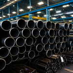


Conductor Pipe
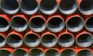
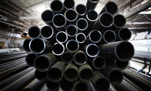
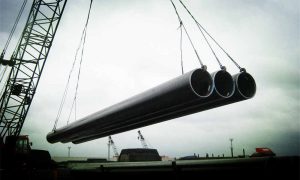
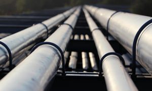
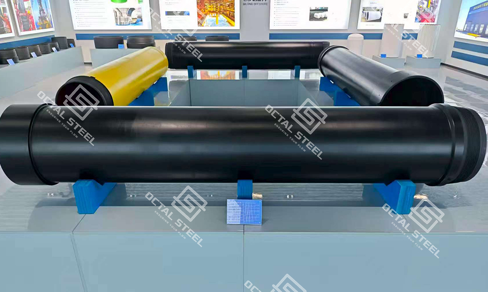
Large-diameter 20″–36″ conductor pipe and risers with quick, BTC, and premium connections for offshore oil & gas well foundations.
Conductor Pipes from 20'' to 36'', engineered for Offshore Reliability. Conductor pipe offshore projects—especially conductor pipe oil and gas drilling—use this first large-diameter casing to stabilize the seabed section and support the wellhead foundation. This page covers conductor pipe, conductor casing, and conductor casing pipes used as the first, outermost string in offshore well construction, including marine conductor pipe scopes where installation method and documentation control release at the yard.
What is Conductor Pipe
Conductor pipe (also referred to as conductor casing, structural casing, or marine conductor in offshore scopes) is the first and largest-diameter casing string installed to stabilize the seabed or near-surface section during offshore oil and gas drilling. Its role extends beyond simply penetrating the seabed: it establishes mechanical stability in unconsolidated formations, isolates seawater zones, and provides an early circulation pathway for drilling fluids. Most importantly, conductor pipe forms the structural foundation for the wellhead system, supporting safe installation of subsequent casing strings and offshore well equipment.
In offshore engineering, this initial casing string is the interface between marine conditions and the well structure. By anchoring subsequent casing strings and supporting heavy platform loads, conductor pipes make possible the reliable construction of wells in environments ranging from shallow continental shelves to ultra-deep waters exceeding 1,960 meters. Modern conductor pipe systems are engineered with modular designs, advanced connector technologies, and rigorous testing protocols, enabling them to withstand both static and dynamic offshore stresses throughout their design life.
In standard casing programs, conductor casing and surface casing are treated as different strings with different objectives and acceptance points; “structural casing” and “marine conductor” are commonly used terms to keep scopes unambiguous during procurement and installation planning.
Key Functions of Conductor Pipe
Conductor pipe plays multiple structural and operational roles that are indispensable for offshore well construction:
-
Seawater Isolation
Prevents seawater intrusion into the well-bore.
Maintains drilling fluid density and circulation efficiency.
Protects against dilution of mud properties in shallow formations. -
Load-Bearing Capacity
Supports the cumulative weight of the drilling platform, risers, and subsequent casing strings.
Transfers axial loads and resists bending moments induced by waves, currents, and platform motion.
Provides structural integrity for wellhead assemblies under cyclic loading. -
Well-bore Stability
Stabilizes unconsolidated sediments near the seabed.
Prevents collapse of upper formations before intermediate casing is installed.
Functions as the “structural skeleton” for the well. -
Foundation for Wellhead and Sub sea Equipment
Provides a secure base for sub sea wellheads, blowout preventers (BOPs), and production trees.
Ensures long-term reliability of sub sea installations by maintaining alignment and load distribution.
Engineering Example: Offshore platforms such as the Sea Swift modular platform demonstrate the structural importance of conductor pipe. These systems have shown the capability to support >400 tons of axial and lateral loads while maintaining a design service life of over 25 years, highlighting conductor pipe’s indispensable role in offshore well design.
Practical risk control in the seabed section often centers on washouts, shallow flows, and near-surface formation instability; conductor casing pipes reduce exposure by stabilizing the upper hole and maintaining a controlled return path for early drilling fluids.
Difference between Conductor Pipe and Drilling Riser
Although conductor pipes and drilling risers are both large-diameter tubular systems used in offshore wells, they serve distinct roles:
-
Conductor Pipe: Conductor Pipe: Installed at the seabed as the first casing string in offshore well construction. It provides structural foundation, load transfer, and upper-hole stability for the wellhead and subsequent casing strings.
-
Drilling Riser: A temporary conduit connecting the sub sea wellhead to the surface drilling platform, primarily used in deep-water operations. It enables safe circulation of drilling fluids and pressure control during drilling.
Together, conductor pipes and drilling risers form a complementary system: the former establishes the foundation at the seabed, while the latter extends operational control from the seabed to the surface in deeper waters.
For conductor pipe offshore scopes, conductor pipe oil and gas procurement is often released at the yard only when each lot arrives with matching MTC/NDT and dimensional records, avoiding hold points before running the string.
| Aspect | Conductor Pipe | Drilling Riser |
|---|---|---|
| Function | Permanent structural casing; stabilizes seabed, isolates seawater, and supports wellhead. | Temporary pressure conduit; connects sub sea wellhead to surface drilling rig. |
| Installation Stage | Installed first as the initial casing string, embedded into the seabed. | Installed after wellhead is set, during drilling operations. |
| Operational Scope | Provides foundation and long-term support for shallow-water wells. | Enables fluid circulation, pressure control, and safe drilling in deep-water wells. |
| Permanence | Permanent part of the well structure. | Temporary, retrieved after drilling is complete. |
| Environment | Shallow-water drilling (continental shelf, nearshore). | Deep-water and ultra-deep-water drilling (>2,000 m). |
| Load-Bearing Role | Transfers axial and lateral loads from platform and equipment to the seabed. | Accommodates dynamic motions (waves, currents) through tensioning systems. |
| Diameter Range | Typically 20″–36″. | Larger systems with tension joints, often >21″ ID. |
| Key Equipment Link | Serves as the foundation for sub sea wellheads, BOPs, and casing programs. | Provides conduit between sub sea BOP and surface drilling system. |
In offshore well construction, conductor pipe and drilling riser solve different problems in sequence. The conductor string anchors the well at the seabed and provides a stable structural base for the wellhead, while the drilling riser extends circulation and operational control between the subsea stack and the surface rig during drilling. Read together, the two systems separate “foundation stability” from “drilling circulation and pressure management,” which helps keep scopes and acceptance criteria clear.
Difference Between Conductor Casing and Surface Casing
| Comparison Point | Conductor Casing (Conductor Pipe) | Surface Casing |
|---|---|---|
| Position in Program | First, outermost, large-diameter string at the seabed/near-surface section. | Next string after conductor; supports the upper wellbore and provides a stronger isolation base for deeper drilling. |
| Primary Purpose | Seabed stability, seawater zone isolation, structural foundation for wellhead and subsequent strings. | Zonal isolation in shallow formations, stronger wellbore integrity for the next drilling interval. |
| Diameter and Wall Design | Large OD selected for foundation loads and installation method; WT tied to axial/lateral loads and soil capacity. | Smaller than conductor; design focuses on casing integrity and cemented isolation for the next section. |
| Acceptance Focus | OD/WT tolerance, ovality, straightness, weld integrity, end prep/connector consistency, handling protection, documentation completeness. | Casing integrity, connection performance, cementing compatibility, and isolation requirements for the next drilling phase. |
Conductor casing and surface casing are both “early strings,” but they are procured and accepted against different risks. Conductor casing pipes are released when fit-up, handling protection, and lot-by-lot documentation support a clean run at the seabed section; surface casing focuses more on integrity and isolation readiness for deeper drilling intervals.
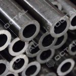
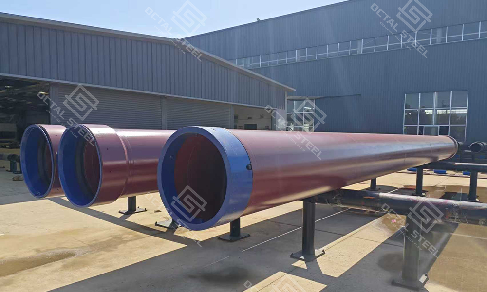
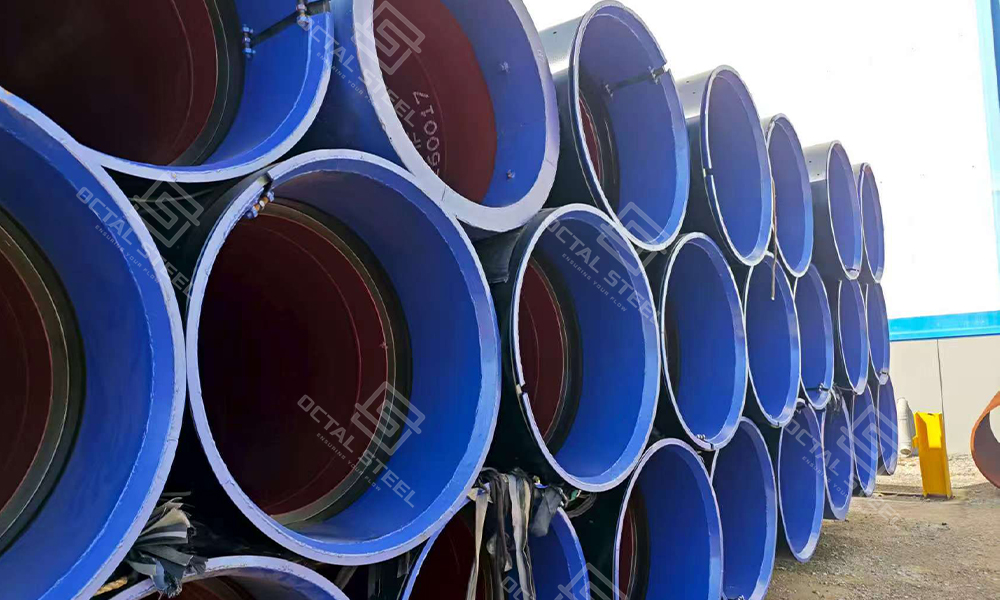
Manufacturing Standards and Capabilities
Octal Steel supplies large-diameter conductor pipes with sizes ranging from 20″ to 36″, tailored to both shallow-water and frontier offshore projects. These conductor casing sizes are typically selected from the drilling program and seabed conditions, linking diameter and wall thickness to foundation loads and installation method. Conductor pipe materials are chosen for weldability, fatigue resistance, and seawater corrosion exposure in offshore environments.
-
Material Selection
Carbon-manganese steels for structural strength.
Low-alloy steels with enhanced weld-ability and fatigue resistance.
Optional corrosion-resistant coatings for long-term durability. -
Fabrication Process
Precision rolling and longitudinal welding.
Heat treatment for controlled micro-structure.
Advanced machining to achieve strict tolerances. -
Standards Compliance
API, ISO, and DNV requirements for offshore well construction.
Conformity with international NDT protocols for weld and body inspection.
For marine conductor pipe packages, manufacturing capability is measured by repeatability across lots—stable OD/WT control, consistent end preparation/connector geometry, and inspection records that align with the yard’s incoming acceptance checklist.
conductor pipe specifications
Conductor pipe specifications for offshore drilling commonly define diameter and wall thickness range, length, manufacturing route (rolled and welded), and dimensional tolerances required for wellhead fit-up. Typical specification scope includes OD/WT range, straightness and ovality limits, end preparation, connector type, coating requirements, NDT scope, and documentation (MTC and inspection/test records).
Conductor pipe installation planning (driven, jetted, or drilled and cemented) changes what matters most in the specification. The same OD can fail offshore if ovality, straightness, or end protection are not controlled to match the installation method.
• OD/WT tolerance and minimum wall verification by lot
• Ovality and straightness limits tied to connector fit-up and running behavior
• Length tolerance and tally discipline (piece count, joint length distribution, heat/lot segregation)
• End preparation / connector type and protector requirements
• Welding route and weld inspection scope (weld + body NDT where required)
• Coating/paint scope and repair criteria for marine handling damage
• Documentation pack scope (MTC, NDT reports, dimensional reports, traceability list)
Conductor Pipe Installation Methods and What They Change in the Specification
| Installation Method | Typical Field Behavior | Specification / Acceptance Emphasis |
|---|---|---|
| Driven | High impact loading; risk of end damage and local deformation during driving. | End protection, ovality control, straightness, weld integrity, connector robustness, handling features, and lot consistency. |
| Jetted | Hydraulic jetting assists penetration; stability and alignment remain critical. | Straightness, connector fit-up, dimensional repeatability, coating tolerance for marine exposure, and documentation completeness. |
| Drilled & Cemented | Hole is drilled before running; cementing and alignment set the base for the next strings. | Dimensional control for running/centralization, end preparation/connector consistency, weld NDT scope, and traceability by lot. |
Regardless of method, conductor casing pipes are commonly released when the receiving team can verify three things quickly: dimensional consistency for fit-up, stable weld quality, and a complete documentation pack by lot.
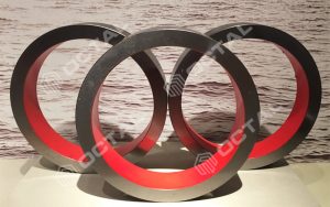
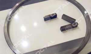
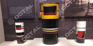
Connection Technologies
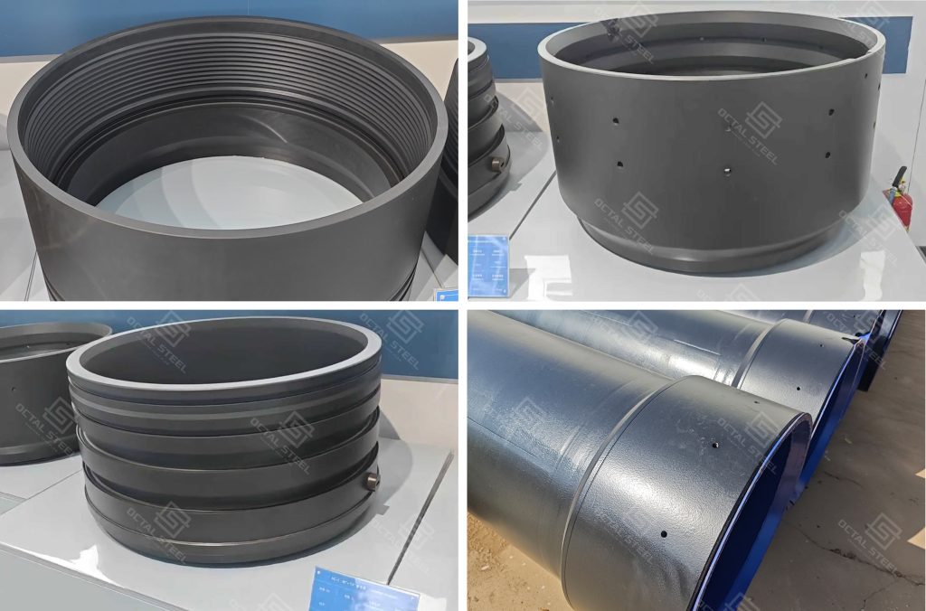
The efficiency and safety of conductor pipe installation largely depend on its connection system. Octal Steel offers three primary options:
-
Quick Connectors (Preferred)
Designed for rapid make-up and break-out.
Reduce rig time by up to 30%.
Provide reliable mechanical strength and sealing integrity. -
BTC (Buttress Threaded & Coupled)
A cost-effective, conventional solution.
Offers proven reliability in moderate offshore conditions. -
Premium Connections
Engineered for HPHT (high pressure, high temperature) wells.
Deliver gas-tight sealing and extreme load resistance.
Suitable for complex and deep-water environments.
Each connector type is validated for tensile strength, bending resistance, fatigue performance, and sealing integrity under marine environmental simulations.
Connector selection is usually driven by installation tempo, load profile, and reusability expectations. Quick connectors are often chosen to reduce offshore running time and handling exposure; BTC is commonly used for conventional scopes where cost and familiarity are prioritized; premium connections are typically specified when the load/sealing envelope is tighter or when project specifications require higher connection performance margins.
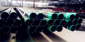
Design and Handling Features
• Pin & Box connectors with metal thread protectors for secure transport and storage.
• Plastic O-rings to enhance sealing reliability and corrosion resistance.
• Integrated lifting eyes for safe offshore handling.
• Custom connector solutions engineered for specific project conditions.
For conductor pipe offshore logistics, handling features are not cosmetic. Thread/connector protectors, lifting design, and stack/transport discipline directly affect ovality at the ends, fit-up speed at the yard, and the probability of rework before conductor running.
Quality Control and Testing
| Quality Control Stage | What Is Verified | Deliverable Records / Documents |
|---|---|---|
| Non-Destructive Testing (NDT) | Ultrasonic (UT), radiographic (RT), and magnetic particle testing (MT) on welds and pipe body | NDT reports tied to weld identification and piece marking Weld identification / traceability records (as specified) |
| Dimensional Verification | Straightness, wall thickness, roundness/ovality, OD/WT verification per lot or agreed sampling plan | Dimensional reports (OD/WT, ovality, straightness) by lot or by agreed sampling plan Measurement records aligned with piece/lot IDs |
| Simulated Marine Testing | Accelerated corrosion and fatigue testing in artificial seawater and cyclic load environments (when specified) | Test reports for corrosion/fatigue simulations (when specified) |
| Material Traceability | Heat / lot traceability maintained through production and shipment | MTC / heat traceability list by lot Piece-level marking list aligned with lot IDs |
| End Preparation & Connector Control | End preparation condition, connector geometry consistency, and protector installation before dispatch | Connector / end preparation records Protector confirmation records |
| Coating / Paint Inspection | Coating/paint scope compliance and repair acceptance, including holiday checks when required | Coating/paint reports (when specified) Repair / holiday records (if applicable) |
| Packing, Tally & Shipment Matching | Shipment integrity verified so each joint’s marking matches documents and packing lists | Packing list and tally matching piece-level markings to the documentation set |
This inspection process is designed to close both technical verification and release documentation in one loop: NDT and dimensional control confirm weld integrity and fit-up consistency, while marine simulation (when specified), traceability, connector/end records, coating reports, and piece-level tally ensure every joint can be accepted and signed off by lot without re-checks—supporting compliant offshore delivery and predictable conductor running schedules.
Applications of Conductor Pipe
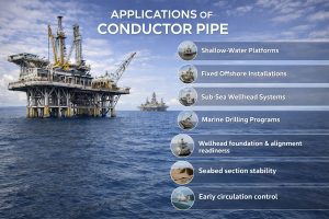
| Application Setting | Typical Use | What the Conductor String Must Enable |
|---|---|---|
| Shallow-water platforms | Jack-ups and modular structures where the first large-diameter string is installed early to stabilize the upper hole. | Wellhead foundation and alignment readiness for the next casing strings |
| Fixed offshore installations | Projects requiring structural load transfer from wellhead-related equipment into the seabed section. | Wellhead foundation and alignment readiness for the next casing strings Seabed section stability in unconsolidated formations with washout exposure |
| Sub-sea wellhead systems | Initial casing string that supports sub-sea wellheads and early well construction hardware. | Wellhead foundation and alignment readiness for the next casing strings Early circulation control where shallow zones and seawater isolation must remain stable during initial drilling |
| Marine drilling programs | Programs where seabed stability and seawater isolation are critical in the first drilling interval. | Seabed section stability in unconsolidated formations with washout exposure Early circulation control where shallow zones and seawater isolation must remain stable during initial drilling |
These application cases can be summarized as one outcome-driven scope: conductor casing pipes are selected to stabilize the seabed section, isolate seawater and weak near-surface zones, and deliver a reliable foundation and alignment base for the wellhead and the next casing strings. In practice, offshore teams prioritize predictable release—traceable lots and inspection documentation that clear incoming acceptance quickly—so conductor running and early circulation can proceed without schedule disruption.
Where Conductor Casing Sits in the Casing Program
A typical casing program moves from largest diameter at the top to smaller strings deeper in the well. Conductor casing is the first and outermost string that stabilizes the seabed/near-surface section and provides the structural base for the wellhead. After the conductor string, surface casing is commonly run to establish stronger shallow isolation and integrity for the next drilling interval. Intermediate casing (when used) manages more complex formations and wellbore stability deeper down, while production casing (or a liner) supports the producing interval and completion design.
Conclusion
Conductor pipe is the first barrier, structural skeleton, and foundation of offshore wells. Its importance lies not only in providing immediate well-bore stability but also in ensuring the long-term integrity of sub sea wellhead systems. With diameters up to 36″, advanced connector technologies, and strict quality assurance, Octal Steel delivers conductor pipe solutions that meet the toughest requirements of offshore oil and gas development.
For projects in shallow-water environments, conductor pipe is indispensable. For deep-water operations, conductor pipe works in tandem with drilling risers to ensure safe, efficient, and reliable well construction.
For conductor casing pipes, “works offshore” means the seabed section clears acceptance without re-check loops—dimensional consistency supports fit-up, handling protection reduces end damage, and the documentation pack arrives complete enough to release the string on schedule.
On offshore conductor pipe packages, procurement usually fails in the small details—OD/WT tolerance not matching the driving/jetted plan, connector/end prep inconsistent across lots, or NDT and traceability arriving late and blocking release.
OCTAL runs conductor pipe supply as a controlled package rather than a loose shipment: the sizing range, wall schedule, end preparation, coating scope, and required documents are confirmed against the drilling program before production release, so what arrives on site matches the installation method and acceptance checklist.
During manufacture, the focus stays on what changes offshore outcomes—dimensional consistency for fit-up, stable weld quality, and verification records that can be signed off without back-and-forth. A typical case is a multi-lot 30″–36″ conductor pipe order where mixed heats and missing inspection records can force re-checks and hold points at the yard; with a factory-controlled route, the factory inspection package is built lot-by-lot (MTC, dimensional reports, and NDT results) and shipped with the pipes, so the receiving team can clear IQC quickly and avoid schedule slip before conductor running. The result is less rework at the seabed section, fewer installation interruptions caused by document gaps, and a cleaner handover to the next casing strings and wellhead foundation activities.
For marine conductor pipe scopes, lot segregation and marking discipline are treated as part of the deliverable. When piece-level identity, connector condition, and inspection records align, conductor pipe installation can proceed without stop-start verification at the yard.
FAQ
Q1: What is conductor in offshore platform?
A1: The conductor is the first large-diameter casing installed at the seabed to stabilize the upper formations, isolate seawater zones, and provide the structural base for the wellhead and subsequent casing strings.
Q2: What is the purpose of conductor casing in offshore drilling?
A2: Conductor casing provides initial wellbore stability in the seabed section, isolates seawater and weak near-surface zones, and carries foundation loads so the wellhead and the next casing strings can be installed in alignment.
Q3: What is the difference between conductor casing and surface casing?
A3: Conductor casing pipes are the first, outermost large-diameter string focused on seabed stability and wellhead foundation; surface casing is typically the next string that strengthens shallow isolation and integrity for deeper drilling intervals.
Q4: How is conductor casing installed offshore?
A4: Conductor casing is commonly installed by driving, jetting, or drilling and cementing, with installation method influencing the specification emphasis on ovality/straightness, end protection, connector consistency, and documentation readiness for yard release.
Q5: What are common conductor casing sizes for offshore wells?
A5: Common conductor casing sizes are typically large-diameter strings selected from the drilling program and seabed conditions; many offshore projects specify conductor pipe in the 20”–36” range, with wall thickness defined by axial/lateral loads, soil capacity, and installation method.
Q6: What are typical conductor pipe specifications for offshore oil and gas projects?
A6: Typical conductor pipe specifications define OD/WT range, length, manufacturing route (rolled and welded), straightness/ovality limits, end preparation or connector type, coating requirements for seawater exposure, NDT coverage, and the required documentation package such as MTC and inspection/test records.
Social Share