Your Responsible Supplier Partner for Oil and Gas Products.
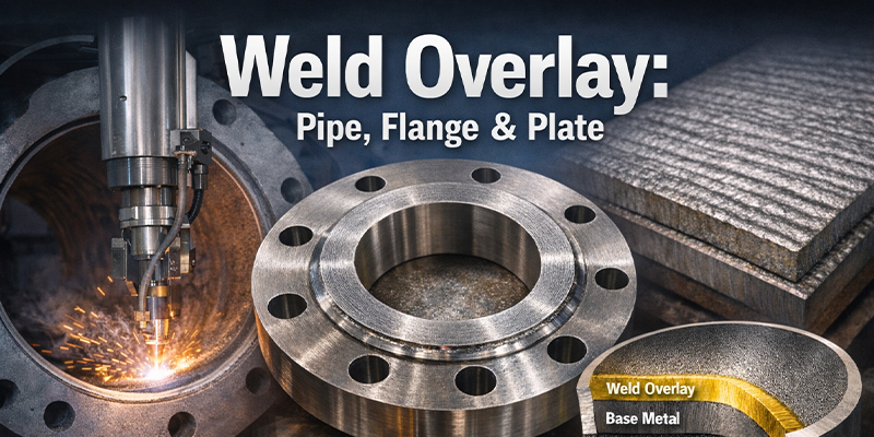
Weld Overlay: Pipe, Flange & Plate
Weld Overlay: Pipe, Flange & Plate
What weld overlay means
Weld overlay is a metal overlay route where overlay welding deposits a functional alloy layer on a base metal surface so the wetted surface meets corrosion or wear requirements. In project documents, weld overlay cladding, cladding welding, clad welding, and welding overlay cladding are often used as near-synonyms; in supplier narratives, hi tech welding sometimes appears as a shorthand for automation or process control. The technical alignment typically comes from how thickness, chemistry/dilution, and boundary continuity are defined and verified.
Deliverables are commonly described in three forms: weld overlay pipe (also written as weld overlay clad pipe or overlay pipe), weld overlay flange, and weld overlay plate (overlay plate). Similar scope in exchangers is frequently framed as heat exchanger cladding.
For a broader CRA comparison that includes pipe cladding options, see:
CRA Clad, Lined, Weld Overlay Pipe Cladding- Bimetal Pipes
Process characteristics and controllable variables
From a process perspective, a weld overlay process aims to achieve continuous coverage while balancing dilution, HAZ effects, and residual stress under a defined heat-input window. In practical engineering discussions, the recurring variables include:
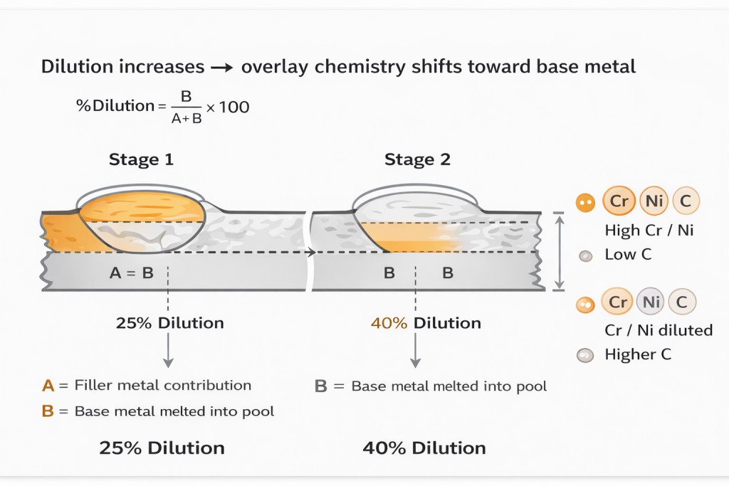
• Dilution and chemistry shift: deviation between nominal alloy and as-deposited surface chemistry
• Thickness vs effective thickness: post-overlay machining changes minimum effective thickness distribution
• Coverage continuity and bead overlap: overlap weld / welding overlap may appear as wording for overlap strategy at boundaries
• Defect morphology and evaluation: surface-breaking indications and subsurface indications are treated differently and typically align with the project’s NDT scheme
Different overlay welding process routes (e.g., GTAW/SAW/PTA or laser clad) tend to present different windows and outcome distributions for these variables.
Equipment routes and automation context
A weld overlay cladding machine generally implies stronger trajectory control and richer parameter logging—common examples include internal bore cladding systems for pipes, automated facing systems for flanges, and strip/wire overlay lines for plates.
In repetitive or large-area work, automated weld overlay often improves repeatability of thickness and overlap, and makes parameter records easier to structure. The phrase disgester automated weld overlay (as written in some requirement texts) usually points to large-area overlays where mapping, repair rules, and re-inspection closure matter more than the equipment label itself.
Laser clad is frequently associated with low dilution and controlled heat input, while also being more dependent on a tighter process window and equipment capability.
Materials and application logic
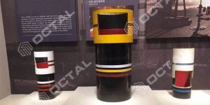
Corrosion overlays
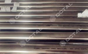
Inconel 625 cladding weld overlay is widely referenced in corrosive service narratives. Contract language often includes inconel 625 overlay welding and inconel overlay welding. The discussion typically centers on surface chemistry, dilution control, and boundary continuity after machining.
For alloy identity and common supply forms:
Inconel 625 / Nickel Alloy 625 / UNS N06625 Pipe and Tube
For sour service boundaries, NACE MR0175 / ISO 15156 is frequently used as a governing framework (project material datasheets prevail).
Wear overlays
Chromium carbide systems are commonly framed as chromium carbide overlay welding for abr
Product forms and typical placement
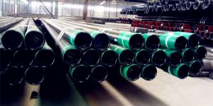
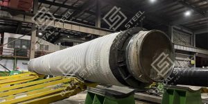
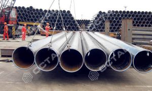
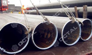
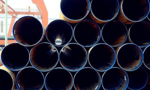
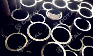
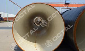
Weld overlay pipe
For weld overlay pipe, engineering attention often concentrates on end transitions, weld-adjacent zones, and coverage continuity at final dimensions. In pipe cladding language, the boundary definition (ID/OD/selected zones, length, and machining allowance) usually drives how measurement and records are organized.
Terms like weld overlay cladding and overlay pipe appear frequently, but closure tends to come from boundary + verification rather than terminology.
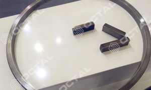
Weld overlay flange
Weld overlay flange scope commonly includes sealing faces, gasket contact areas, and neck transitions. Post-overlay machining to final geometry and surface condition often becomes the focal point of evaluation.
In wellhead/sub-sea interface contexts, API 6A / API 17D is frequently referenced as an interface and acceptance framework (project specifications prevail).
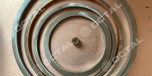
Weld overlay plate
A weld overlay plate (overlay plate) behaves like a machinable overlay base material. Thickness uniformity, thickness mapping in critical zones, flatness, and machining allowance are common discussion anchors. Project texts may use cladding metal or cladding process, while verification still converges on boundary, thickness, chemistry, and inspection closure.
Heat exchanger cladding
Heat exchanger cladding is commonly defined by wetted surfaces—tube sheets, channels, heads, and nozzle transitions. For pressure parts, ASME BPVC Section VIII is often used as a boundary framework for fabrication and acceptance (project documents prevail).
Overlay continuity across fittings and transitions often governs system consistency; elbows, tees, reducers, and flange transitions are typical focus points. For fitting continuity context:
A practical academic framing of weld overlay vs cladding
weld overlay vs cladding is more consistently resolved by formation mechanism and acceptance object than by labels.
• Weld overlay is a deposited overlay; verification typically targets the overlay itself (effective thickness, chemistry/dilution, continuity, and boundary after machining).
• Cladding may describe multiple routes (bonded clad, lined, or deposited overlays). As a result, weld overlay and cladding difference is often closed by explicitly defining “material + process route + verification method.”
Procedure, qualification, and traceable records
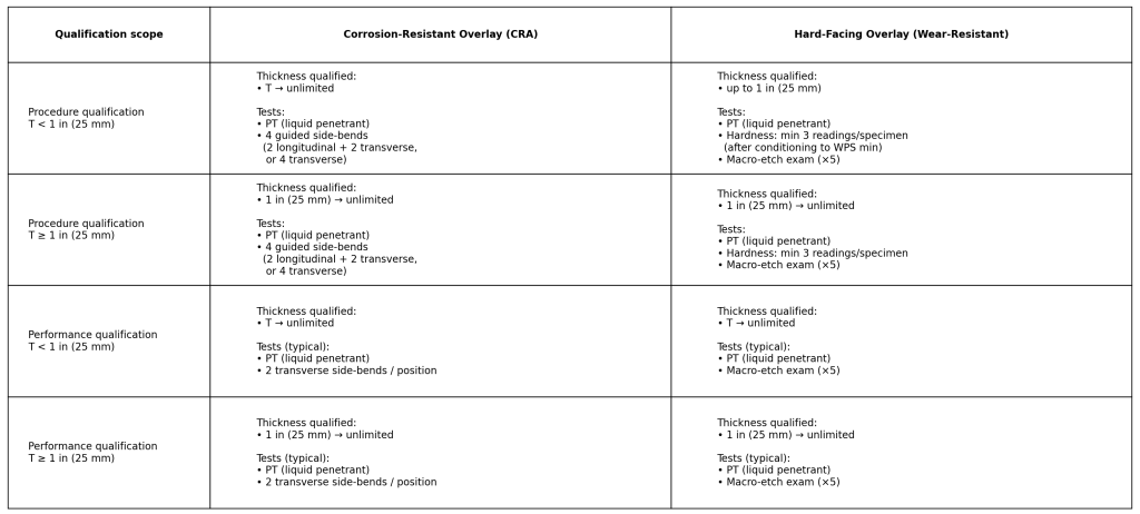
| Overlay thickness on coupon (T) | Typical thickness qualification intent | Typical tests you should expect (example) |
|---|---|---|
| T < 25 mm | Often qualified for wider overlay range when procedure window is stable | Surface-breaking check (PT) + bend/macro set per overlay type |
| T ≥ 25 mm | Thicker overlays tend to require additional verification for soundness & properties | PT + bend set + macro; wear overlays may add hardness mapping |
An overlay welding procedure typically defines how the process window is qualified and verified; for Inconel overlays, inconel overlay welding procedure and inconel 625 overlay welding procedure appear frequently in documentation sets.
Qualification is often aligned with ASME BPVC Section IX. Discussions around a clad welder usually focus on coverage of alloy/position/method/equipment mode.
A more robust technical narrative is built by structuring traceable outputs: weld map, parameter records, thickness mapping, and their linkage to NDE reporting.
Evaluation methods and repair boundary
Evaluation is commonly built from geometry/thickness, chemistry verification (PMI and/or sampling as defined by project rules), NDT scope, and traceability documentation.
Weld overlay repair is widely used in maintenance and re-manufacture; the technical discussion typically centers on repair boundary (area/depth), machining allowance, and the definition of re-inspection scope, with alignment to the original procedure or an approved alternative path.
FAQ
Q1: How is weld overlay and cladding difference usually defined in projects?
A1: It is commonly defined through acceptance objects—boundary definition, effective thickness distribution, chemistry/dilution verification rule, continuity after machining, and the linkage to NDT and record structure—rather than by the label alone.
Q2: What variables most often dominate Inconel 625 overlay welding evaluation?
A2: Surface chemistry/dilution, continuity at transitions, boundary retention after machining, and the alignment between thickness mapping and PMI/chemistry verification records.
Q3: Where is chromium carbide overlay welding most commonly applied?
A3: Abrasive/erosive environments and high-wear contact surfaces; evaluation typically emphasizes hardness window, thickness, a project-defined crack rule, and machining impact on effective thickness.
Q4: Why is the final sealing face central in weld overlay flange discussions?
A4: Because machining to final profile and finish changes boundary and effective thickness distribution, and interface-driven applications frequently reference API 6A / API 17D as an acceptance framework


Tags:CRA Clad Pipe
Related Products
Related Resources
Recent News

Hot Topic
Octal is located in China recognized as a leading supplier, distributor, and manufacturer union in providing piping solutions for oil and gas company. Product ranges in Steel Pipe, Casing and Tubing, Steel Plate, Sucker Rod, Steel Pipe Fittings, Valves, and Equipment for pipelines.
Contact Info
Unit 2544, 25/F, Tower A, Wanda Plaza, Wenfeng District, Anyang, Henan, China & Building A, No.18 Dirun Road, Zhengdong New District, Zhengzhou, Henan, China
+86 372 2157660 / +86 186 3727 1277
[email protected]