Your Responsible Supplier Partner for Oil and Gas Products.
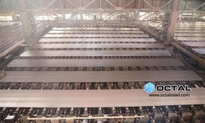
Heavy Steel Plate
Heavy Steel Plate
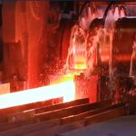
Heavy steel plate rolling and how the route maps to flatness stability
Heavy plate rolling is primarily judged by repeatable control of thickness, shape, and flatness, typically through:
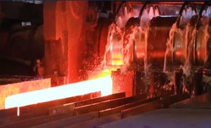
• Reheating and descaling for surface control
• Rolling for thickness, profile, and shape control
• Controlled cooling when property windows require it
• Hot levelling to stabilize flatness on wide and heavy sections
• Plate-by-plate identification for traceability and release
When the goal is fewer seams, lower NDT scale, and more stable assembly outcomes, plate format and shape stability become practical risk controls.
4100mm Heavy and Wide Plate for seam reduction in heavy fabrication
In large panel builds and shell-course fabrication, plate width is not a cosmetic choice. It directly drives how many longitudinal joints enter the weld map, how many UT/RT intersections appear in the ITP, and how much fit-up time sits in front of each welding cycle. For procurement, this becomes a predictable trade: a wider plate can remove an entire seam line, which usually means fewer weld meters, fewer NDT callouts, fewer repair loops, and a cleaner distortion-control plan on large assemblies.
This is where a wide-format starting material helps, especially when the package includes large deck panels, module base frames, box structures, or rolled shells that would otherwise be split into multiple strips. Using a wider plate often allows a simpler cutting plan, fewer part numbers, and fewer plate-to-plate transitions that can slow receiving and traceability closure. It also reduces the chance that one late plate holds a panel from being assembled and released.
A practical example is 4100mm Heavy and Wide Plate, used when the design benefits from larger-format plates and heavy thickness in the same supply window. Buyers typically evaluate this option against a short checklist: whether single-piece weight remains within site lifting capacity, whether transport envelope and packaging can protect edges and surfaces, and whether flatness and camber are controlled tightly enough to avoid corrective work after cutting. When those items are aligned, wider plate format is a straightforward way to reduce fabrication uncertainty without changing the design intent.
Heavy steel plate fabrication and what usually closes approvals
Heavy plate fabrication releases smoothly when the package closes:
• MTC (3.1 or 3.2 as specified) with heat and plate ID traceability
• Dimensional and shape records for thickness, width, length, and defined flatness criteria
• UT or other NDT reports aligned to PO and ITP scope and acceptance class
• Surface and edge condition aligned to cutting and coating interfaces
• Packing and identification discipline that preserves plate-to-heat mapping
In heavy fabrication, traceability and inspection alignment can be as release-critical as grade naming.
Steel plate as starting material and what it becomes
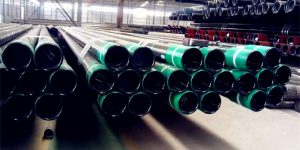
• Pressure equipment and process vessels: shell courses, cylinders, dished heads, exchanger shells, tower sections
• Large welded structures: offshore module base frames, deck panels, skids, gusset plates and load-bearing plates
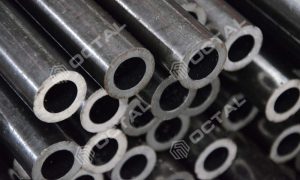
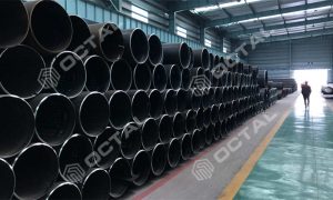
• Cylindrical products: plate-formed welded pipe (e.g., LSAW), rolled shells and structural cylinders, tower sections
• Wear and high-strength components: liners, heavy equipment structural parts, lifting and transport structures
With different delivery conditions and toughness/shape controls, the same nominal plate can behave very differently in rolling/bending, weld HAZ sensitivity, UT outcomes, and dimensional stability after fabrication.
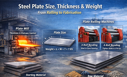
Steel plate size and why format drives seams and NDT
Steel plate size is defined by thickness × width × length, then completed by tolerances, shape limits, and delivery condition. For large panels, shell courses, and heavy welded assemblies, width directly affects:
• Longitudinal seam count and total weld length
• The number of NDT joints (UT/RT workload and rework exposure)
• Fit-up rhythm and distortion control on large assemblies
For schedule-driven packages, plate format becomes a practical lever to reduce downstream variability.
Steel plate thickness: thickness changes the manufacturing route
Steel plate thickness influences:
• Forming feasibility and minimum rolling radius, spring-back control
• Weld preparation, pass count, heat input window, and distortion management
• NDT practicality and inspection planning on heavy welds
• Heat treatment logic on thick-welded parts when required by the code or project
Heavy plate programs usually prioritize thickness consistency and stable flatness after cutting and welding.
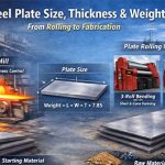
Steel plate weight and a practical calculation
A common estimate uses density near 7.85 t/m³ for carbon and low-alloy steels:
Steel plate weight (kg) = Length (m) × Width (m) × Thickness (mm) × 7.85
Example: 6.0 m × 2.0 m × 20 mm
Weight ≈ 6.0 × 2.0 × 20 × 7.85 = 1884 kg
Weight is used for lifting plans, transport limits, and receiving checks, while final shipping weight is closed by packing lists and measured weights.
Steel Plate Rolling Machine Fabrication Meaning 3-Roll and 4-Roll Bending Rolls
For fabrication, “steel plate rolling machine” usually means bending rolls (3-roll / 4-roll). The plate thickness is not reduced; the machine creates controlled plastic bending to achieve a target radius and seam fit-up.
3-roll plate rolling machine (pyramid / initial-pinch)
A 3-roll machine forms curvature with a three-point bending triangle. The plate is driven by the bottom rolls (or one bottom roll), while the top roll applies bending force and is offset to set the radius. Radius is achieved by progressive passes until the shell reaches target diameter.
Functional control points: radius setting by top-roll offset, spring-back compensation by over-bend + re-roll passes, cone rolling by differential side adjustment/skew. Limitation: edge pre-bend typically needs repositioning and/or flipping, so flat-end length control is weaker and seam fit-up is more operator-dependent.
4-roll plate rolling machine (double-pinch)
A 4-roll machine positively pinches the plate between the top and bottom rolls, while two side rolls move independently to generate bending moment and control radius. The positive grip enables controlled feeding and direct pre-bending of both leading and trailing edges with minimal flipping.
Functional control points: tighter and more repeatable roundness, better flat-end minimization, more stable seam gap control, and more controlled cone rolling via asymmetric side-roll positioning. It is generally more consistent on thicker plates and higher-strength materials because slip is reduced and geometry is held under pinch.
What “control” means in practice
Roundness and fit-up are governed by roll positioning + force control (often hydraulic with encoder/CNC feedback) and by planned over-bend to offset spring-back. For long/thick shells, accuracy is limited by roll deflection, so machines rely on roll crowning/compensation and controlled pass schedules to avoid barrel/hourglass shapes.
Plate category and delivery condition and why it changes weld-ability and forming behavior
Typical delivery conditions and their practical impact:
• As-rolled for general structural needs when toughness windows are not tightly constrained
• Normalized for more uniform structure and stable properties where consistency matters
• TMCP for optimized strength–toughness balance and weld-ability in demanding structural or offshore use
• Quenched and tempered (Q&T) for defined high-strength and toughness windows, with stricter discipline on welding heat input
These choices move the risk focus from nominal strength to fabrication drivers such as HAZ control, UT behavior, spring-back, and low-temperature toughness windows.
Starting Material vs Raw Material in Steel Plate Supply Chains
Operational definitions
Starting material is the controlled, released input to a defined manufacturing step. It sets the auditable start point of a manufacturing route, so traceability, inspection scope, release status, and certification closure run from one fixed boundary.
Raw material is upstream steel-making input such as ore, scrap, alloying elements, deoxidizers, and other consumables. It is managed through metallurgical process control and is typically not treated as a piece-level deliverable chain in a project data package.
The practical difference is boundary control
Starting material defines where the delivery chain begins
Raw material defines how upstream variability is controlled to achieve required chemistry and performance
Why the distinction matters in delivery
Starting material defines where the delivery chain begins and where responsibility becomes auditable. Raw material explains how the mill achieves chemistry and performance but does not normally extend to item-by-item project traceability.
Starting material control criteria and release status
A starting material definition is executable only when it meets three mandatory conditions.
Controlled status
Controlled status means the input is verified and formally released before it is allowed to enter the next step. In practice, release is typically based on six verification blocks: (1) identification and traceability match (heat/plate/lot and mapping integrity), (2) certificate and document validity (MTC completeness, standard/grade/condition, sampling unit alignment), (3) visual and dimensional acceptance (thickness/width/length tolerances, surface condition, edge condition, plate flatness), (4) material condition confirmation (delivery condition and heat treatment status where applicable, hardness/impact requirements when specified), (5) additional testing triggers and results when required (e.g., PMI/UT/retests driven by contract or discrepancies), and (6) controlled release and segregation (released vs hold/quarantine with documented disposition).
Process entry point
The item is explicitly listed as the input to a specific manufacturing step on the route card, manufacturing plan, or traveler.
Traceable identification
The item is identified at least to heat/lot level and remains retrievable through mapping when converted into downstream pieces.
Raw material is defined differently and should be stated differently.
Upstream input
Fed into steel-making and refining operations rather than project-defined fabrication steps.
Process-driven impact
Controlled through charge mix, refining, degassing, and casting parameters to achieve target chemistry, cleanliness, and internal soundness.
Not a piece-level deliverable chain
Normally not expanded into item-by-item traceability evidence in the customer-facing data book, unless a specific regulatory or contractual requirement requires it.
Manufacturing route levels and starting material selection
Starting material changes with the route level being discussed. This is expected because the certified route changes.
Plate mill route
Starting material is commonly the slab. The slab is the controlled input into reheating and rolling, tied to heat identity and governed by defined sampling and test rules.
Downstream fabrication route
Starting material is commonly the released steel plate. The fabricator’s controlled route begins at receiving inspection, certificate verification, marking control, ID inheritance after cutting/forming, and subsequent NDE and dimensional checks.
Route boundary statement rule
Name the route first, then define the starting material for that route. Mixing route start points in one statement creates avoidable audit ambiguity.
Traceability boundary and ID inheritance control
Once starting material is defined, the traceability boundary is fixed. From that boundary onward, traceability must be continuous and evidenced.
Deliverable traceability evidence pack commonly includes four proof sets:
Unique ID rules
Heat No., Plate No., Lot No., Piece ID defined with non-duplicating formats and controlled assignment rules.
ID inheritance control
After cutting, segmentation, beveling, or forming, each child piece inherits traceability through stamping, tags, labels, or controlled paint marking with documented rules.
Trace mapping that can be audited
Any piece ID can be traced back to parent plate and heat, and linked to the specific test records through a controlled mapping table or equivalent record.
Physical-to-document consistency
Physical marking, packing list, inspection reports, and MTC references reconcile without gaps.
Raw-material traceability typically exists as internal mill records
Charge mix sheets, alloy batch tracking, ladle/product analyses, refining and casting logs, and process control records support capability and investigation, but they are not usually the backbone of a project’s piece-level delivery chain.
Certificate closure and inspection scope
Plate supply level typically closes via heat-indexed MTC/CMTR covering chemistry, mechanicals, standard, and sampling rules, plus NDT/HT records if required.
Fabrication level closes from released plate through receiving inspection, ID transfer, NDE/dimensional reports, and final release—bound to piece IDs.
One-line audit wording
Starting material sets the auditable boundary where project traceability and certificate closure begin from a controlled, released input; raw material remains an upstream metallurgical control domain that supports capability rather than forming the piece-level deliverable traceability chain.
FAQ
Q1: What is steel plate in project procurement terms?
A1: Steel plate is flat-rolled steel delivered as individual plates, ordered to a standard and grade with defined steel plate size, steel plate thickness, delivery condition, and verification documents such as MTC and specified NDT.
Q2: How is steel plate weight calculated for logistics and lifting plans?
A2: Steel plate weight is commonly calculated as Length (m) × Width (m) × Thickness (mm) × 7.85, then confirmed by packing list and measured shipping weights.
Q3: Why does steel plate thickness change fabrication risk and inspection scope?
A3: Steel plate thickness affects forming route, weld preparation, heat input control, distortion behavior, and the practicality of NDT coverage, especially on heavy welded assemblies.
Q4: Does steel plate rolling machine mean a mill or a fabrication roller?
A4: Both meanings exist. It can mean the plate mill rolling stand that controls thickness and shape, or the fabrication bending rolls that control cylinder roundness and springback.
Q5: Why does starting material vs raw material matter in documentation?
A5: It defines the traceability boundary. Starting material is the controlled input (slab or released plate) that carries heat identity into certificates and inspection closure, while raw material is upstream of that boundary.


Tags:steel platesteel plate manufacturer
Related Products
Related Resources

Recent Faqs


Rencent Articles


Hot Topic


Custom Posts
Octal is located in China recognized as a leading supplier, distributor, and manufacturer union in providing piping solutions for oil and gas company. Product ranges in Steel Pipe, Casing and Tubing, Steel Plate, Sucker Rod, Steel Pipe Fittings, Valves, and Equipment for pipelines.
Contact Info
Unit 2544, 25/F, Tower A, Wanda Plaza, Wenfeng District, Anyang, Henan, China & Building A, No.18 Dirun Road, Zhengdong New District, Zhengzhou, Henan, China
+86 372 2157660 / +86 186 3727 1277
[email protected]